

ADSL2+ Ethernet USB Combo Router – Easy Start
Page 1 of 42

ADSL2+ Ethernet USB Combo Router – Easy Start
Table of Contents
Preliminary Pages Page
Table of Contents .................................................................................................................2
Chapter 1 – Introduction....................................................................................................5
1.1 Minimum Requirements...................................................................5
1.2 ADSL Router Package .....................................................................6
1.3 ADSL Router Overview...................................................................7
1.3.1 Front Indicators (Ethernet USB Combo Router)..............................7
1.3.2 Back Panel Indicators (Ethernet USB Combo Router)....................8
1.3.3 Front Indicators (Ethernet Router)...................................................9
1.3.4 Back Panel Indicators (Ethernet Router)........................................10
1.4 Typical ADSL Router Connection.................................................11
Chapter 2 - Connecting the ADSL Router to Your PC / Notebook..............................12
2.1 Connecting to the Ethernet.............................................................12
2.2 Connecting to the ADSL Line........................................................13
2.3 Checking Your Connections...........................................................14
2.4 Connecting to the USB Port (For Ethernet USB Combo Router Only)
........................................................................................................14
2.5 Connecting to the Power Outlet .....................................................15
2.6 Powering ON..................................................................................15
Chapter 3 – Configuring Your Ethernet Network Card ...............................................16
3.1 For Windows® 98 Second Edition / Windows® Me .....................16
3.2 For Windows® 2000 / Windows® XP...........................................17
Chapter 4 – Installing Your USB Driver (For Ethernet USB Combo Router Only)..19
4.1 For Windows® 98 Second Edition..................................................19
®
4.2 For Windows
4.3 For Windows
ME.........................................................................21
®
2000.......................................................................22
4.4 For Windows® XP..........................................................................23
4.5 For Macintosh® OS 10.2 & above.................................................25
Chapter 5 – Configuring Your Internet Browser...........................................................30
5.1 Microsoft® Internet Explorer™ (based on IE 5.5).............................30
5.2 Netscape Navigator ........................................................................30
Page 2 of 42

ADSL2+ Ethernet USB Combo Router – Easy Start
Chapter 6 – Router Setup Utility .....................................................................................31
6.1 Running Setup Utility.....................................................................31
6.2 Microsoft® Windows XP Professional x64 Edition ......................36
Chapter 7 – Setup ADSL Router via Quick Start ..........................................................39
Chapter 8 – Maintenance..................................................................................................41
8.1 Maintenance Concepts....................................................................41
8.2 Preventive Maintenance .................................................................41
8.3 Preventive or Scheduled Maintenance (PM) Tasks........................41
8.4 PM or Scheduled Maintenance Tasks ............................................42
8.5 PM Tools & Test Equipment..........................................................42
Page 3 of 42
ADSL2+ Ethernet USB Combo Router – Easy Start
Safety Summary Messages
WARNING
HIGH VOLTAGE
is used in the equipment. Make sure equipment is properly grounded
BEFORE opening. Failure to observe safety precautions may result in electric
shock to user.
CAUTION
Check voltages before connecting equipment to power supplies. Wrong
voltages applied may result in damage to equipment.
Page 4 of 42

ADSL2+ Ethernet USB Combo Router – Easy Start
Chapter 1 – Introduction
Thank you for purchasing our ADSL2+ Ethernet USB Combo Router. The ADSL Router
provides you with a high-speed broadband Internet connection using your existing phone line
that at the same time allows you to make phone calls.
The ADSL Router can be connected to any computer/notebook with a USB Port (for Ethernet
USB Combo router only) or 10/100 Base-T Ethernet card. For multiple users connection, you
may connect your computers/notebooks to both the Ethernet Port and USB Port on the ADSL
Router at the same time or expand the Ethernet connection of the ADSL Router with an Ethernet
Hub / Switch.
This documentation assumes that you have already installed an Ethernet card on your
computer/notebook.
1.1 Minimum Requirements
• Pentium
• A CD-ROM Drive
• Ethernet card installed with TCP/IP Protocol (required only if you are connecting
to the ETHERNET port of your ADSL Router)
• USB port (required if you are connecting to the USB Port of your ADSL Router,
for Ethernet USB Combo Router only)
• Host Operating Systems support for USB (For Ethernet USB Combo Router
only):
- Windows® 98 Second Edition
- Windows® Me
- Windows® 2000
- Windows® XP
- Windows® XP x64 Edition
®
MMX 233MHz
- Macintosh OS 10.2 & above
• OS independent for Ethernet
• Web Browser support:
- Microsoft Internet Explorer 4.0 (or later versions)
- Netscape® Navigator 3.02 (or later versions)
Page 5 of 42
ADSL2+ Ethernet USB Combo Router – Easy Start
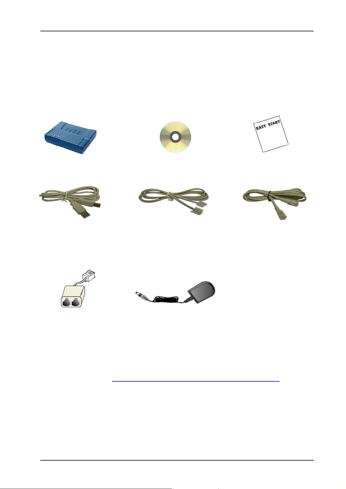
1.2 ADSL Router Package
Fig 1-1 below shows the ADSL Router Package. For any missing items, please contact your
dealer immediately.
ADSL Router Utility CD Easy Start Manual
USB Cable Telephone Cable (RJ11) CAT-5 UTP Straight Ethernet
(For Ethernet USB Network Cable (RJ45)
Combo Router only)
POTS-Splitter (Optional) Power Adapter (DC 9V)
Figure 1-1 : ADSL Router Package
Depending on your country of purchase, your package may or may not come with a POTS
Splitter. The POTS Splitter is required if you are connecting a Telephone Set to the Ethernet
Modem. Please refer to Chapter 2 Section 2.2 - Connecting to the ADSL Line for details.
POTS-Splitter can also be purchased from your dealer.
Page 6 of 42
ADSL2+ Ethernet USB Combo Router – Easy Start
1.3 ADSL Router Overview
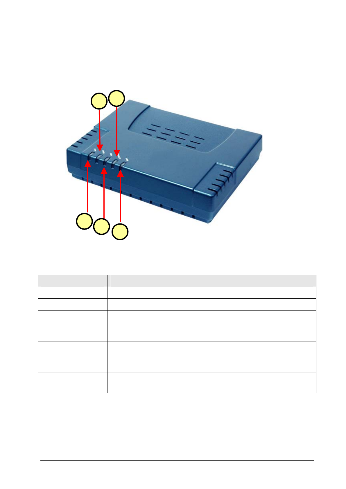
1.3.1 Front Indicators (Ethernet USB Combo Router)
Fig 1-2 shows the front indicators of the Ethernet USB Combo Router.
4
2
Label Description
1 PPP
2 PWR
3 DSL
4 ETH/ACT
5 USB
1
3
5
Figure 1-2 : Front Indicators (Ethernet USB Combo Router)
Lights up when the PPP connection is established.
Lights up when power is supplied to the Router.
Lights up when the ADSL connection is established.
Flickers when the ADSL Router is trying to establish a connection with
the ADSL Service Provider.
Lights up when the Ethernet cable is properly connected from your
ADSL Router to the Ethernet Card.
Flickers when the ADSL is transmitting / receiving data.
Lights up when the USB device driver is successfully installed in your
Computer/ Notebook.
Page 7 of 42
ADSL2+ Ethernet USB Combo Router – Easy Start
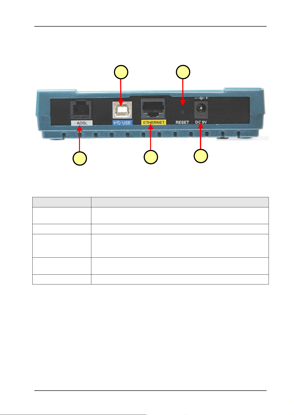
1.3.2 Back Panel Indicators (Ethernet USB Combo Router)
Fig 1-3 shows the back panel indicators of the Ethernet USB Combo Router.
1 DSL
2
1
Figure 1-3 : Back Panel Indicators (Ethernet USB Combo Router)
3
4
Label Description
Telephone jack (RJ-11) to connect to your Telephone Wall Socket
(ADSL line).
5
2 USB
3 ETHERNET
4 RESET
5 DC 9V
USB Port to connect to the USB port on your Computer/Notebook.
10/100 Base-T Auto-MDI/MDIX (allows either cross or straight cable)
Ethernet jack (RJ-45) to connect to your Ethernet Network card or
Ethernet Hub/Switch.
To reset the ADSL Router, simply press the reset button for about 10
seconds (all customised settings that you have saved will be lost!).
To connect to the Power Adapter that comes with your package.
Page 8 of 42
ADSL2+ Ethernet USB Combo Router – Easy Start
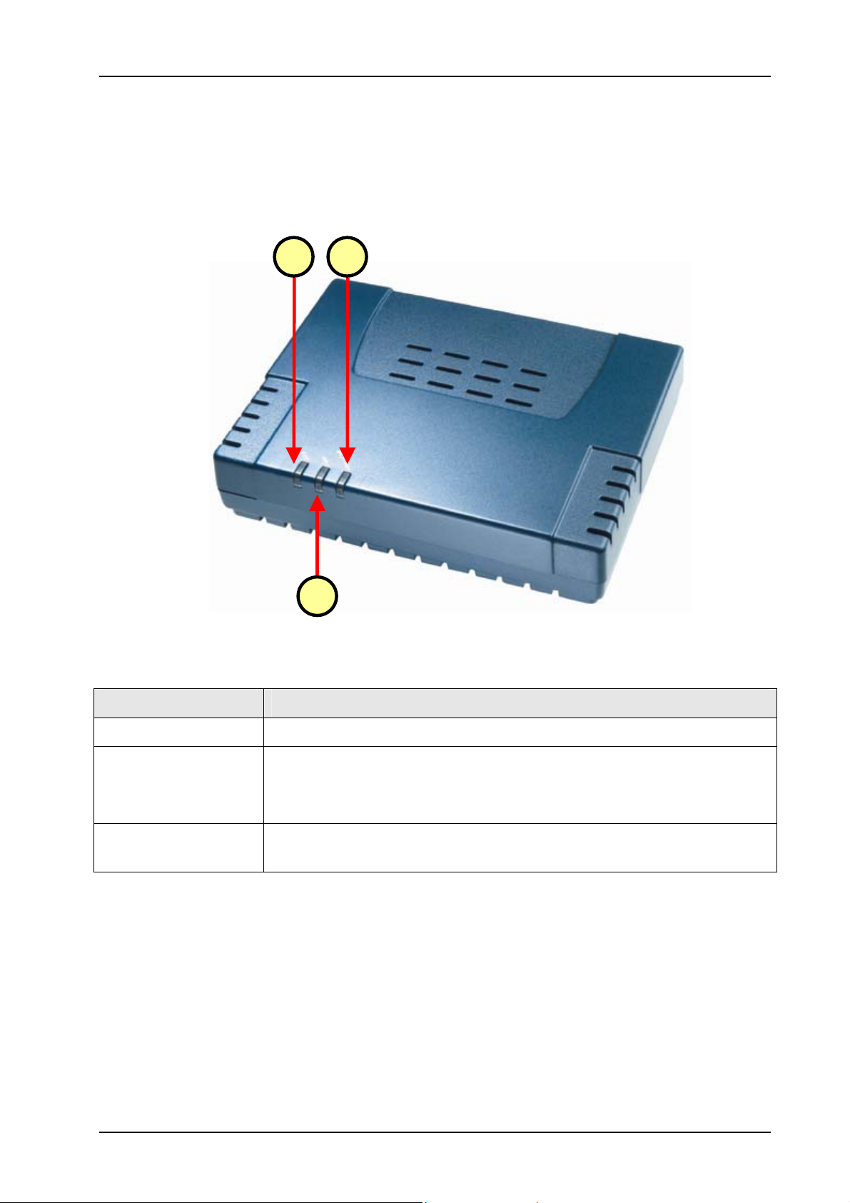
1.3.3 Front Indicators (Ethernet Router)
Fig 1-4 shows the front indicators of the Ethernet Router.
1
3
2
Figure 1-4 : Front Indicators (Ethernet Router)
Label Description
1 PWR
2 DSL
3 ETH/ACT
Lights up when power is supplied to the Router.
Lights up when the ADSL connection is established.
Flickers when the ADSL Router is trying to establish a connection with
the ADSL Service Provider.
Lights up when the Ethernet cable is properly connected from your
ADSL Router to the Ethernet Card.
Page 9 of 42
ADSL2+ Ethernet USB Combo Router – Easy Start
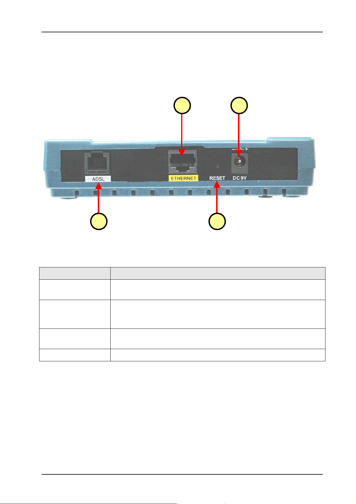
1.3.4 Back Panel Indicators (Ethernet Router)
Fig 1-5 shows the back panel indicators of the Ethernet Router.
4
1
2
3
Figure 1-5 : Back Panel Indicators (Ethernet Router)
Label Description
1. DSL
2. ETHERNET
3. RESET
4. DC 9V
Telephone jack (RJ-11) to connect to your Telephone Wall Socket
(ADSL line).
10/100 Base-T Auto-MDI/MDIX (allows either cross or straight cable)
Ethernet jack (RJ-45) to connect to your Ethernet Network card or
Ethernet Hub/Switch.
To reset the ADSL Router, simply press the reset button for about 10
seconds (all customised settings that you have saved will be lost!).
To connect to the Power Adapter that comes with your package.
Page 10 of 42
ADSL2+ Ethernet USB Combo Router – Easy Start
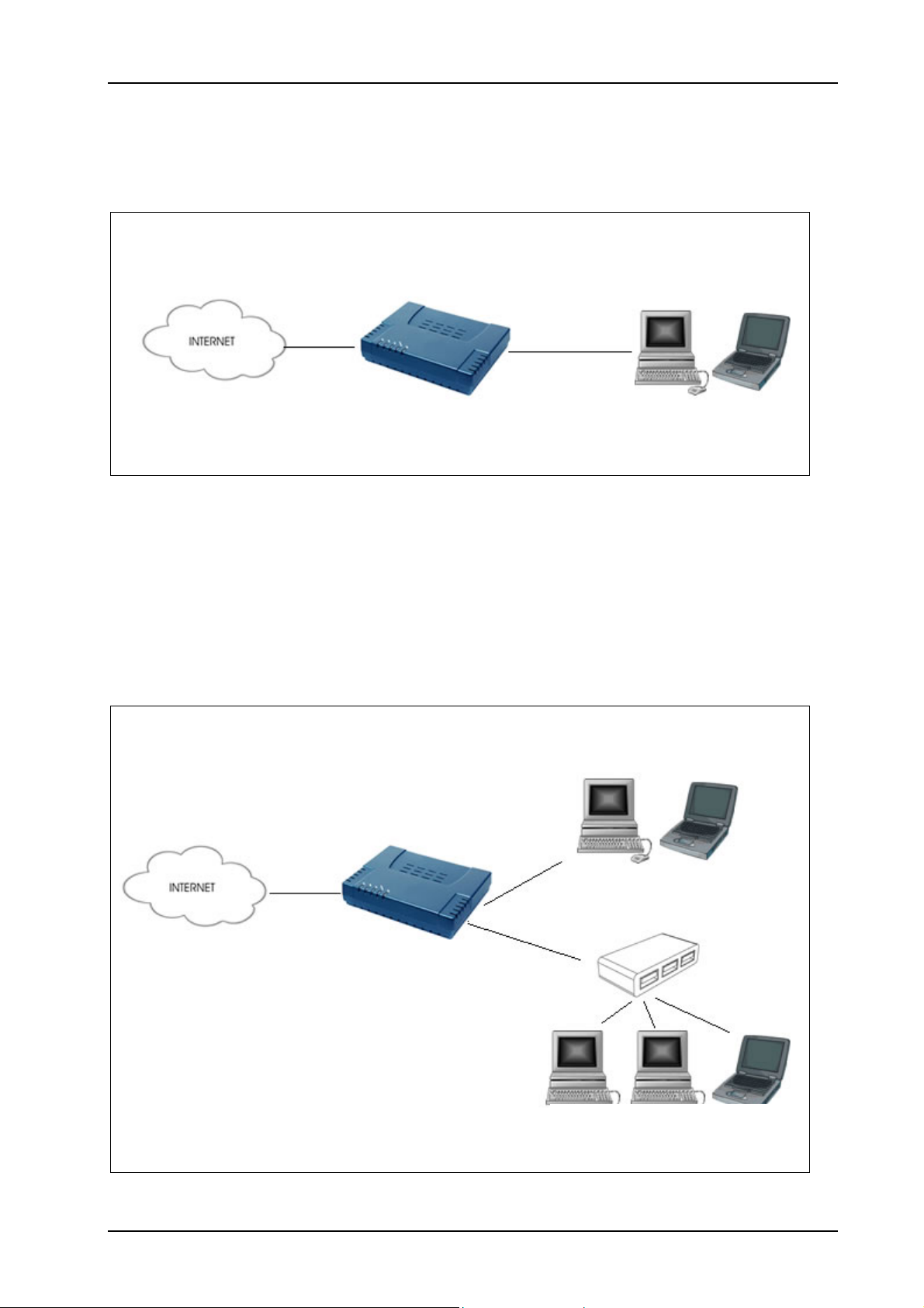
1.4 Typical ADSL Router Connection
Fig 1-6 below shows a typical single user connection.
Computer/Notebook
with Ethernet Network
Card or USB Port
Ethernet / USB
Cable
Figure 1- 6 :Single User Connection Diagram
To connect to multiple computers/notebooks, you may further expand one of the Ethernet Ports
via an Ethernet Hub/Switch. For details on how to connect to the Ethernet Switch/Hub, please
refer to the documentation that comes with the unit. See Fig 1-7.
Computer/Notebook with
USB Port
USB
Computer/Notebook with
Ethernet Network Card
Figure 1-7 : Multiple PCs Connection
Page 11 of 42
ADSL2+ Ethernet USB Combo Router – Easy Start
Chapter 2 - Connecting the ADSL Router to Your PC /
Notebook
CAUTION !
Power off your Computer/Notebook or/and any connected devices before
connecting to the ADSL Router!
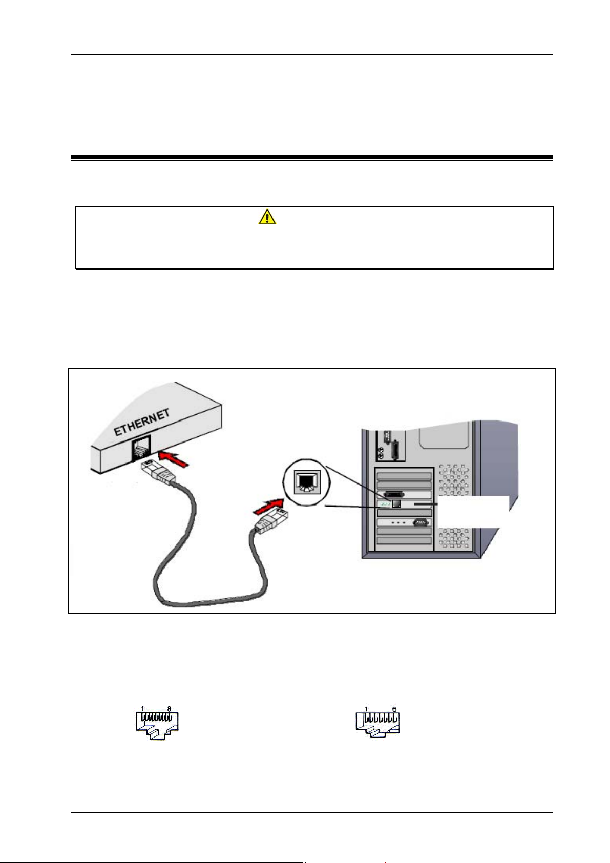
2.1 Connecting to the Ethernet
Connect your computer(s)/notebook(s) to the ADSL Router as illustrated. The following
illustration shows the connection of a single computer. See Fig 1-8.
Back View of
ADSL Router
Back view of a
Computer
Ethernet Port
Ethernet
Network Card
Ethernet
Network Cable
Figure 1-8 : Connecting to Ethernet
Do not be mistaken by an Ethernet Port and a Line Port. Picture A below illustrates that of an
Ethernet port, whilst Picture B shows a Line port.
A : ETHERNET
B : LINE
Page 12 of 42
ADSL2+ Ethernet USB Combo Router – Easy Start
p
j
p
p
p
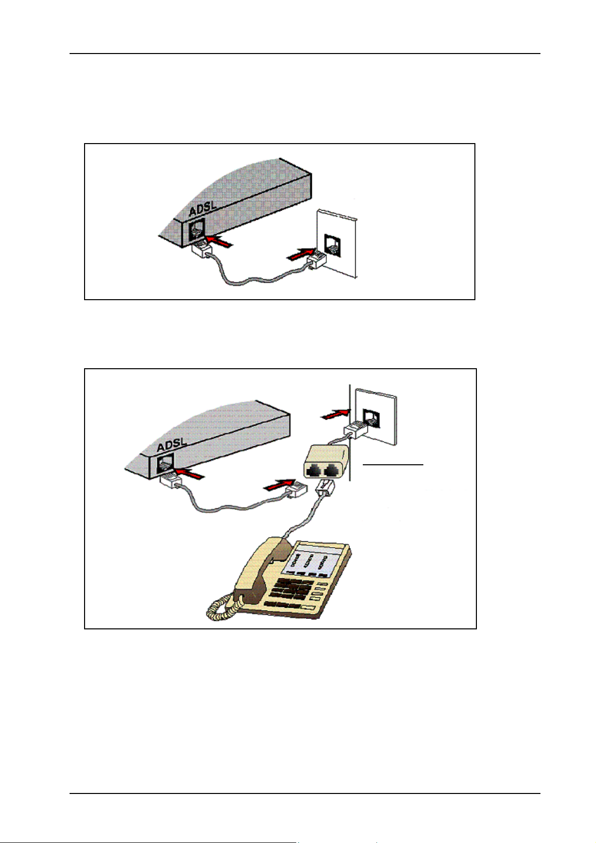
2.2 Connecting to the ADSL Line
Fig 1-9 shows the connection of the ADSL Ethernet Modem to the ADSL Line.
Back View of
ADSL Router
Telephone
Wall Socket
hone Cable
Tele
Figure 1-9 : Connecting to the ADSL Line
Fig 1-10 shows the connection of the ADSL Line and Telephone set.
Tele
hone wall socket
Back View of
ADSL Router
POTS Splitter
hone Cable
Tele
Connect the
telephone set to the
ack labeled TEL or
PHONE and the
telephone cable to
the jack labeled
LINE.
Tele
hone Set
Figure 1-10 : Connection of ADSL Line & Telephone set
The POTS Splitter (with built-in Microfilter) is a device that allows you to connect both your
Telephone cable and Telephone Set to the same Telephone Wall Socket. The device at the same
time helps to eliminate background noise on the telephone line, ensuring the best possible phone
performance.
Page 13 of 42

ADSL2+ Ethernet USB Combo Router – Easy Start
2.3 Checking Your Connections
NOTE: Please check your connections before proceeding.
Ensure all connections are carefully plugged in as shown in Fig 1-11.
Back view of
ADSL Router
To your
Power Outlet
To your
Telephone
Wall Socket
(ADSL Line)
To the Ethernet Port on your
Computer(s)/Notebook(s)
Figure 1-11 : Checking Connections
2.4 Connecting to the USB Port (For Ethernet USB Combo Router
Only)
Ensure that the USB cable is plugged in as shown in Fig 1-12.
Back view of
ADSL Router
USB Cable
Back view of a
computer
USB Port
Figure 1-12 : Connecting the USB ports
Page 14 of 42

ADSL2+ Ethernet USB Combo Router – Easy Start
2.5 Connecting to the Power Outlet
See Fig 1-13 for connection to the power outlet.
Back View of the
ADSL Router
Connect the other end of
the Power Adapter to the
Power
Figure 1-13 : Connecting Power Outlet
2.6 Powering ON
a) Power on the Power Outlet that is connected to your ADSL Router.
b) Power on your Computer(s)/Notebook(s).
Page 15 of 42

ADSL2+ Ethernet USB Combo Router – Easy Start
Chapter 3 – Configuring Your Ethernet Network Card
If your computer/notebook is connected to the Ethernet Port of the ADSL Router, proceed with
the following instructions. If your computer/notebook is connected to the USB Port of the ADSL
Router, proceed with Chapter 4.
The illustrated screen shots serve only as examples. For any dissimilarity, please follow the
instructions closely as prompted on your Computer.
NOTE: Proceed with this section ONLY if your computer/notebook is connected to
the Ethernet Port of your ADSL Router.
3.1 For Windows® 98 Second Edition / Windows® Me
Proceed with the steps below.
1. From your Windows desktop, right-click on the Network Neighborhood icon. Select
Properties.
2. From the Configuration tab, select TCP/IP-> xxx where xxx refers to the model of your
Ethernet Card that is connected to your ADSL Router.
3. Click Properties as show below in Fig 1-14.
Figure 1-14 : Network settings
Page 16 of 42

ADSL2+ Ethernet USB Combo Router – Easy Start
4. Click the IP Address tab.
5. Select the option Obtain an IP address automatically and click OK to save the settings.
See Fig 1-15.
Figure 1-15 : TCP/IP Properties
6. Ensure that your ADSL Router is powered ON.
7. Restart your system.
8. Proceed to Chapter 5.
3.2 For Windows® 2000 / Windows® XP
Windows® 2000:
a. From your Windows desktop, right-click on the icon My Network Places and select
Properties.
b. At the Network and Dial-up Connections window, right-click on the Local Area
Connection icon and select Properties.
Windows® XP: (Instructions are based on default Start menu option)
a. From your Windows desktop, click Start > All Programs > Accessories >
Communications > Network Connections.
b. Right-click on the Local Area Connection icon that reflects the model of your
Ethernet Card that is connected to your ADSL Router and click Properties.
Ensure that the field Connect Using indicates the model of your Ethernet Card that is connected
to your ADSL Router.
Page 17 of 42

ADSL2+ Ethernet USB Combo Router – Easy Start
NOTE: This is important especially if you have more than one Local Area
Connection icons displayed at the Network and Dial-up Connections /
Network Connections window. Ensure that you have selected the correct
one.)
1. Select Internet Protocol (TCP/IP) and click Properties. See Fig 1-16.
Figure 1-16 : Local Area Connection properties
2. Select the option Obtain an IP address automatically and click OK. See Fig 1-17.
Figure 1-17 : TCP/IP Properties
3. Click OK again to close.
4. Ensure that your ADSL Router is powered ON.
5. Restart your system.
6. Proceed to
Chapter 5.
Page 18 of 42

ADSL2+ Ethernet USB Combo Router – Easy Start
Chapter 4 – Installing Your USB Driver (For Ethernet
USB Combo Router Only)
Setup utility will install the USB driver automatically. If it fails to install, follow the steps below
for USB installation. Proceed with this section ONLY if your computer/notebook is connected to
the USB Port of your ADSL Router. The following screen shots illustrated serve only as
examples. For any dissimilarity, please follow closely the instructions prompted on your
Computer/Notebook.
For Windows® 98 Second Edition users, you may be prompted for your Windows CD-ROM.
Have it ready by your side.
4.1 For Windows® 98 Second Edition
Proceed with the steps below:
1. Power ON your computer to start the Windows Operating System.
2. Insert the Installation CD into your CD-ROM Drive.
3. At the prompt click Next. See Fig 1-18.
Figure 1-18 : Add New Hardware Wizard Prompt
4. Select Search for the best driver for your device (Recommended) option and click
Next. See Fig 1-19.
Figure 1-19 : Driver Search
Page 19 of 42

ADSL2+ Ethernet USB Combo Router – Easy Start
5. Select on CD-ROM drives option and click Next. See Fig 1-20.
Figure 1-20: CD-ROM Selection
NOTE: Depending on your system’s configuration, you may be prompted for your
Windows CD-ROM during installation. At the prompt, replace the
Installation CD in your CD-ROM Drive with your Windows CD-ROM and
click OK. At the Copying Files dialog box, enter the path of your Windows
CD-ROM and click OK.
6. Click Finish to complete the USB driver installation.
7. Restart your system when prompted.
8. Proceed to Chapter 5.
Page 20 of 42

ADSL2+ Ethernet USB Combo Router – Easy Start
4.2 For Windows® ME
Proceed with the steps below:
1. Power ON your computer to start the Windows Operating System.
2. Place the Installation CD into your CD-ROM Drive.
3. At the following prompt, select Specify the location of the driver (Advanced) option
and click Next. See Fig 1-21.
Figure 1-21 : Specifying Driver Location
4. Click Removable Media option and click Next. See Fig 1-22.
Figure 1-22 : Driver Location
Page 21 of 42

ADSL2+ Ethernet USB Combo Router – Easy Start
5. Click Next again to proceed installation with the indicated driver.
6. Click Finish to complete the USB driver installation.
7. Restart your system when prompted.
8. Proceed to Chapter 5.
4.3 For Windows® 2000
Proceed with the steps below:
1. Power ON your computer to start the Windows Operating System.
2. Place the Installation CD into your CD-ROM Drive.
3. At the prompt shown in Fig 1-23, click Next.
Figure 1-23 : Hardware wizard
4. Select Search for a suitable driver for my device (recommended) option and click
Next. See Fig 1-24.
Figure 1-24 : Search Driver
Page 22 of 42

ADSL2+ Ethernet USB Combo Router – Easy Start
5. Click CD-ROM drives option and click Next.
6. At the next prompt, click Next to proceed installation with the indicated driver.
7. You may be prompted with Digital Signature Not Found dialog box during installation.
(This happens when Windows detects your driver has a new version).
8. Click Yes to proceed with the installation.
9. Click Finish when prompted.
10. Proceed to Chapter 5.
4.4 For Windows® XP
Proceed with the steps below:
1. Power on your computer to start Windows.
2. Place the Installation CD into your CD-ROM Drive.
3. At the prompt shown below in Fig 1-25, select Install from a list or specific location
(Advanced) option and click Next.
Figure 1-25 : Installation from Location
Page 23 of 42

ADSL2+ Ethernet USB Combo Router – Easy Start
4. Click Search removable media option and click Next. See Fig 1-26.
Figure 1-26 : Search removable media
5. You may be prompted with Hardware Installation dialog box. (This happens when
Windows detects your driver as a new version).
6. Click Continue Anyway to proceed with the installation. See Fig 1-27.
Figure 1-27 : Driver New Version prompt
7. Click Finish when prompted.
8. Proceed to Chapter 5.
Page 24 of 42

ADSL2+ Ethernet USB Combo Router – Easy Start
4.5 For Macintosh® OS 10.2 & above
Proceed with the steps below:
1. Power on your computer to start Mac OS X (10.2 & above).
2. Place the Installation CD into your CD-ROM Drive.
3. Access to the CD-ROM drive and double-click on Mac folder. Select and open the file
USBCDCEthernetv1_2.pkg, as shown in Fig 1-28.
Figure 1-28 : Installation from Location
4. A Macintosh® Administrator authentication window will be prompted. Enter your
administrator login Name and Password or phrase. Click on OK to proceed. See Fig 1-
29.
Figure 1-29 : Authentication
Page 25 of 42

ADSL2+ Ethernet USB Combo Router – Easy Start
5. Installation program will start. Click Continue to proceed with the installation. See
Fig 1-30.
Figure 1-30 : Installation program
6. Select a destination disk to install the software. Click Continue to proceed with the
installation. See Fig 1-31.
Figure 1-31 : Select destination disk
Page 26 of 42
ADSL2+ Ethernet USB Combo Router – Easy Start
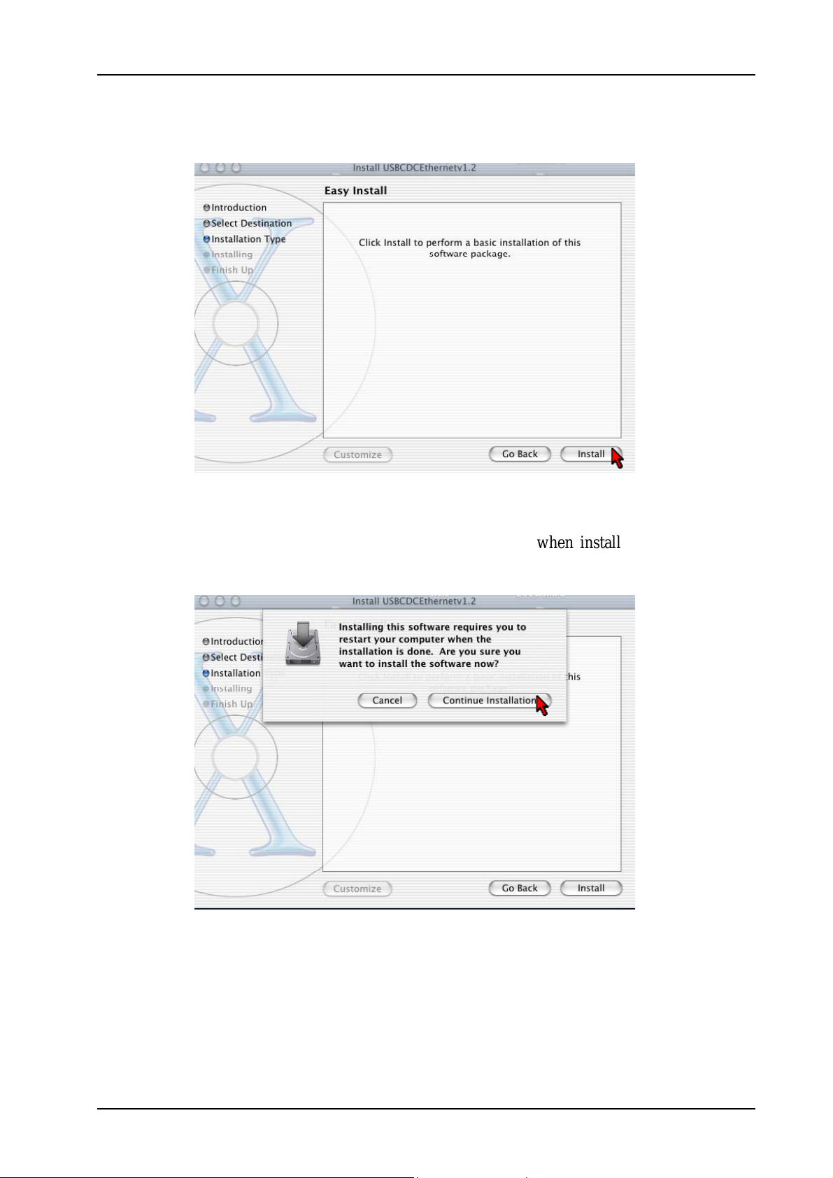
7. Click Install to perform the installation. See Fig 1-32.
Figure 1-32 : Easy Install
8. The system will prompt you to restart your computer when installation is completed.
Click Continue Installation to proceed. See Fig 1-33.
Figure 1-33 : Continue Installation prompt
Page 27 of 42

ADSL2+ Ethernet USB Combo Router – Easy Start
9. Click Restart to finish installing the software. See Fig 1-34.
Figure 1-34 : Software installed successfully
10. The system will bootup upon restart. Select System Preferences from the dock. Select
Network to choose the network adaptor connected to the router. See Fig 1-35.
Select This
Figure 1-35 : System Preferences
Page 28 of 42

ADSL2+ Ethernet USB Combo Router – Easy Start
11. Select Ethernet Adaptor (enXX) as your adaptor under Show option. Your IP Address,
subnet mask, router IP should appear. Click Apply Now. See Fig 1-36.
12. Proceed to Chapter 7.
Figure 1-36 : Network settings
Page 29 of 42

ADSL2+ Ethernet USB Combo Router – Easy Start
Chapter 5 – Configuring Your Internet Browser
5.1 Microsoft® Internet Explorer™ (based on IE 5.5)
1. From your Windows desktop, double-click on your Internet Explorer icon to launch
your Browser.
2. From the Menu, click Tools and select Internet Options... .
3. Select the Connection tab. Click the field, 'Never dial a connection'. (This option will
be grayed off if you have not installed an analog modem on your computer/notebook
before.
4. Click the LAN Settings... button. Ensure that your Proxy Server is not enabled.
5. Click OK to close the dialog box.
6. You may now proceed to Chapter 6.
5.2 Netscape Navigator
1. From your Windows desktop, double-click on your Navigator icon to launch your
Browser.
2. Click Options > Network Preferences.
3. Select Proxies. Ensure that the No Proxies option is selected. OR
4. Click Edit > Preferences.
5. Select Advanced and click Proxies. Ensure that the option Direct Connection to the
Internet is enabled.
6. Click OK for changes to take effect.
7. You may now proceed to Chapter 6.
Page 30 of 42

ADSL2+ Ethernet USB Combo Router – Easy Start
Chapter 6 – Router Setup Utility
(For Windows 98 SE/ ME/ 2000/ XP Users ONLY)
NOTE: This chapter is for Windows User only. Please use the Setup Utility
Installation CD provided to setup the USB driver and Internet connection.
For Windows 98 SE user, you may be prompted for your Windows CDROM during installation. At the prompt, replace the Installation CD in
your CD-ROM Drive with your Windows CD-ROM and click OK.
6.1 Running Setup Utility
Insert the Setup Utility CD into the CD-ROM drive. The utility will auto-run and the screen as
shown below will appear. (Note: If it does not auto-run, access to the CD-ROM drive and
execute Setup.exe). Pictures of different router models will appear when you position the mouse
cursor over the available options. Depending on your model, select ADSL2+ Ethernet Modem
or ADSL2+ Ethernet USB Router to begin setup. See Fig 1-37.
Figure 1-37 : Setup Utility – Select Router Model
NOTE: Do not plug in your USB cable before running the setup utility. Plug in
only when prompt to do so. Otherwise connect the Ethernet cable before
proceeding.
Page 31 of 42
ADSL2+ Ethernet USB Combo Router – Easy Start
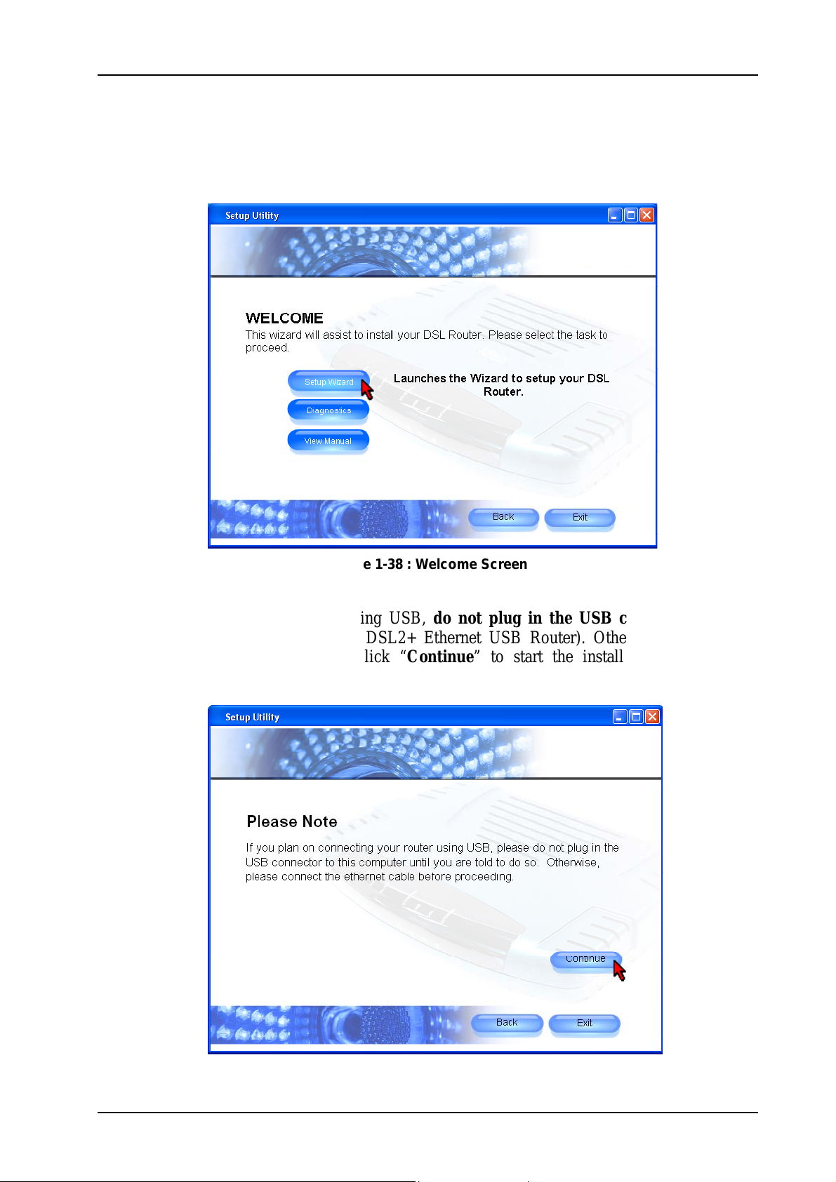
Upon clicking on the above options, you will come to the Welcome screen. If you are setting up
your router for the first time, please click “Setup Wizard” to setup your DSL router. See
Fig 1-38.
Figure 1-38 : Welcome Screen
If you are connecting your router using USB, do not plug in the USB connector until the
system prompts you to do so (for ADSL2+ Ethernet USB Router). Otherwise, connect the
Ethernet cable before proceeding. Click “Continue” to start the installation process. See
Fig 1-39.
Figure 1-39 : Important Note
Page 32 of 42

ADSL2+ Ethernet USB Combo Router – Easy Start
Setup Wizard will proceed to install the USB driver. Plug in USB cable when prompt (For
Windows XP Professional x64 Edition, refer to Chapter 6.2). If you are using Ethernet cable,
click “Cancel”. See Fig 1-40. At this point, plug in your telephone cable. Remember to switch
on the power of your router!
Figure 1-40 : Driver Installation
Setup Wizard will begin to check your router and DSL connection. See Fig 1-41.
Figure 1-41 : Setup in progress
Page 33 of 42

ADSL2+ Ethernet USB Combo Router – Easy Start
For connecting to the Internet, please enter the Username and Password, VPI and VCI
provided by your ISP. You need to select the protocol. Click “Continue” to proceed. Please
contact your ISP if you are unsure of what to enter. See Fig 1-42.
Figure 1-42 : Internet Connection Setup
Setup wizard will try to connect to the Internet. See Fig 1-43.
Figure 1-43 : Setup in Progress
Page 34 of 42

ADSL2+ Ethernet USB Combo Router – Easy Start
Upon successful connection, a summary of your settings will be displayed. You can choose to
print or save the settings. To print, you need to have a printer installed. Click “Continue” to
proceed. See Fig 1-44.
Figure 1-44 : Summary of Settings
The setup is complete and you are now able to browse the Internet. Click on the cube to start
surfing the Internet. See Fig 1-45.
Figure 1-45 : Successful Connection
If you have trouble connecting your router to the Internet, click Diagnostics to troubleshoot.
For more information, refer to the user manual which you can access by clicking View Manual
on the Welcome screen Fig 1-38.
Page 35 of 42

ADSL2+ Ethernet USB Combo Router – Easy Start
6.2 Microsoft® Windows XP Professional x64 Edition
Upon plugging in your USB cable after the system prompt, a Found New Hardware Wizard
dialog box will appear. Select No, not this time and click Next. See Fig 1-46.
Figure 1-46 : Found New Hardware Wizard
Select Install the software automatically (Recommended) and click Next. See Fig 1-47.
Figure 1-47 : Install Software Automatically
Page 36 of 42

ADSL2+ Ethernet USB Combo Router – Easy Start
Please wait until the wizard installs the USB driver. See Fig 1-48.
Figure 1-48 : Installation in progress
You may be prompted with Hardware Installation dialog box. (This happens when Windows
detects your driver as a new version).
Click Continue Anyway to proceed with the installation. See Fig 1-49.
Figure 1-49 : Driver New Version prompt
Page 37 of 42
ADSL2+ Ethernet USB Combo Router – Easy Start
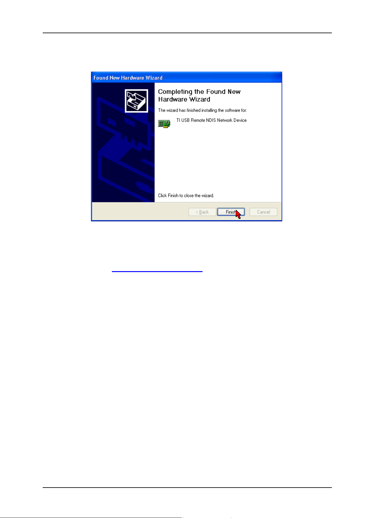
After installation of USB driver has completed, click Finish. See Fig 1-50.
Figure 1-50 : Installation Complete
Setup utility will resume to check your router and DSL connection, and try to connect to the
Internet. Refer back to Setup Wizard in Chapter 6.1.
Page 38 of 42

ADSL2+ Ethernet USB Combo Router – Easy Start
Chapter 7 – Setup ADSL Router via Quick Start
a) From your Internet Browser, key in 192.168.1.1 at the address bar and hit <Enter>. See Fig
1-51.
OR
Figure 1-51 : Logging-In
Upon successful login, this page will be displayed. See Fig 1-52. You need to enter the
Username, Password, VPI and VCI provided by the ISP. Click Connect.
Figure 1-52 : Quick Start
Page 39 of 42

ADSL2+ Ethernet USB Combo Router – Easy Start
Upon successful connection to the Internet, the screen as shown in Fig 1-53 will appear. This
would show the connection status information.
Figure 1-53 : Status Information
Page 40 of 42

ADSL2+ Ethernet USB Combo Router – Easy Start
Chapter 8 – Maintenance
This section explains the maintenance concepts and provides instructions on preventive
maintenance necessary to ensure that the system and equipment are maintained at its optimum
operating condition.
8.1 Maintenance Concepts
This Maintenance concept is categorized into one (1) main category:
1. Preventive Maintenance (PM)
8.2 Preventive Maintenance
Preventive Maintenance (PM) or Scheduled Maintenance is the systematic care, servicing and
inspection of equipment to prevent failures, reduce downtime and maintain it in a optimum
operational condition.
8.3 Preventive or Scheduled Maintenance (PM) Tasks
In general, the following PM tasks are recommended to be performed:
a. Pre-Operational Checks
These are tasks to be performed before operation or mission to ensure that the system is
operationally ready:
1. Check for completeness of the system, ensure all equipment and accessories are in place
and in good condition;
2. Check that all switches are at OFF position;
3. Check that maintenance records indicate the equipment are in a fully safe state for
operation;
4. Perform system power up, ensure that the indicators are lit accordingly;
5. Perform self test, view diagnostic messages and device status and ensure no fault or error
messages are displayed or reported;
b. Post-operation Checks
These tasks are performed as a procedural post operation check to ensure system is properly shut
down.
Perform system power down procedure; ensure that all power supply connections and switches
are turned OFF.
Page 41 of 42

ADSL2+ Ethernet USB Combo Router – Easy Start
8.4 PM or Scheduled Maintenance Tasks
PM tasks are to be performed at intervals recommended as in Table 1-1.
When performing PM cleaning tasks:
a) Use a lint-free, non-abrasive cloth to perform cleaning – DO NOT use any solvent, abrasive
cleaning agents or tissue paper. If equipment is dirty (e.g. with thick dust), use a soft damp
cloth and wipe the surface of the equipment gently.
b) Wipe off immediately any water or liquid from rack, equipment or accessories.
c) Place equipment/accessories in a dry and clean area. DO NOT expose equipment to direct
sunlight and moisture.
d) Report any signs of faulty cables to the higher maintenance authority for follow-up.
Table 1-1 : PM Tasks and Schedule
S/N FREQUENCY PROCEDURE
1. Monthly a. Inspect the equipment for any physical damage or sign of corrosion
b. Perform visual inspection and cleaning on the modem
c. Perform LED test on the modem to ensure that the unit is
operationaly ready
d. Perform visual inspection and cleaning on the modem
e. To ensure outdoor unit has no faulty cables and the unit is
operationally ready.
f. To check for loose connections.
2. 24-monthly a. To re-furbish un-sheltered modems
b. Perform led test on modems and link test through its firmware to
ensure it is operationally ready.
8.5 PM Tools & Test Equipment
For PM tasks, no special tools and test equipment are required.
© Copyright February 2006. All Rights Reserved.
Page 42 of 42
 Loading...