

Axis Q6055-C User Manual
AXISQ6055-CPTZDomeNetworkCamera
InstallationGuide

Legalconsiderations
Videosurveillancecanberegulatedbylawsthatvaryfrom
countrytocountry.Checkthelawsinyourlocalregion
beforeusingthisproductforsurveillancepurposes.
Thisproductincludesone(1)H.264decoderlicense.To
purchasefurtherlicenses,contactyourreseller.
Liability
Everycarehasbeentakeninthepreparationofthis
document.PleaseinformyourlocalAxisofceofany
inaccuraciesoromissions.AxisCommunicationsABcannot
beheldresponsibleforanytechnicalortypographicalerrors
andreservestherighttomakechangestotheproductand
manualswithoutpriornotice.AxisCommunicationsAB
makesnowarrantyofanykindwithregardtothematerial
containedwithinthisdocument,including,butnotlimited
to,theimpliedwarrantiesofmerchantabilityandtnessfor
aparticularpurpose.AxisCommunicationsABshallnot
beliablenorresponsibleforincidentalorconsequential
damagesinconnectionwiththefurnishing,performance
oruseofthismaterial.Thisproductisonlytobeusedfor
itsintendedpurpose.
Intellectualpropertyrights
AxisABhasintellectualpropertyrightsrelatingto
technologyembodiedintheproductdescribedinthis
document.Inparticular,andwithoutlimitation,these
intellectualpropertyrightsmayincludeoneormoreof
thepatentslistedatwww.axis.com/patent.htmandoneor
moreadditionalpatentsorpendingpatentapplicationsin
theUSandothercountries.
Thisproductcontainslicensedthird-partysoftware.See
themenuitem“About”intheproduct’suserinterfacefor
moreinformation.
ThisproductcontainssourcecodecopyrightAppleComputer,
Inc.,underthetermsofApplePublicSourceLicense2.0
(seewww.opensource.apple.com/apsl).Thesourcecodeis
availablefromhttps://developer.apple.com/bonjour/
Equipmentmodications
Thisequipmentmustbeinstalledandusedin
strictaccordancewiththeinstructionsgiveninthe
userdocumentation.Thisequipmentcontainsno
user-serviceablecomponents.Unauthorizedequipment
changesormodicationswillinvalidateallapplicable
regulatorycerticationsandapprovals.
Trademarkacknowledgments
AXISCOMMUNICATIONS,AXIS,ETRAX,ARTPECandVAPIX
areregisteredtrademarksortrademarkapplicationsofAxis
ABinvariousjurisdictions.Allothercompanynamesand
productsaretrademarksorregisteredtrademarksoftheir
respectivecompanies.
Apple,Boa,Apache,Bonjour,Ethernet,InternetExplorer,
Linux,Microsoft,Mozilla,Real,SMPTE,QuickTime,UNIX,
Windows,WindowsVistaandWWWareregistered
trademarksoftherespectiveholders.Javaandall
Java-basedtrademarksandlogosaretrademarksor
registeredtrademarksofOracleand/oritsafliates.
TM
UPnP
isacerticationmarkoftheUPnP
Corporation.
SD,SDHCandSDXCaretrademarksorregisteredtrademarks
ofSD-3C,LLCintheUnitedStates,othercountriesorboth.
Also,miniSD,microSD,miniSDHC,microSDHC,microSDXC
arealltrademarksorregisteredtrademarksofSD-3C,LLC
intheUnitedStates,othercountriesorboth.
TM
Implementers
Regulatoryinformation
Europe
ThisproductcomplieswiththeapplicableCEmarking
directivesandharmonizedstandards:
•ElectromagneticCompatibility(EMC)Directive
2014/30/EU.SeeElectromagneticcompatibility(EMC)
2.
•LowVoltage(LVD)Directive2014/35/EU.SeeSafety3.
•RestrictionsofHazardousSubstances(RoHS)Directive
201 1/65/EU.SeeDisposalandrecycling3.
Acopyoftheoriginaldeclarationofconformitymaybe
obtainedfromAxisCommunicationsAB.SeeContact
information3.
Electromagneticcompatibility(EMC)
Thisequipmenthasbeendesignedandtestedtofulll
applicablestandardsfor:
•Radiofrequencyemissionwheninstalledaccordingto
theinstructionsandusedinitsintendedenvironment.
•Immunitytoelectricalandelectromagneticphenomena
wheninstalledaccordingtotheinstructionsandused
initsintendedenvironment.
USA
Thisequipmenthasbeentestedusingashieldednetwork
cable(STP)andfoundtocomplywiththelimitsfora
ClassAdigitaldevice,pursuanttopart15oftheFCCRules.
Theselimitsaredesignedtoprovidereasonableprotection
againstharmfulinterferencewhentheequipmentis
operatedinacommercialenvironment.Thisequipment
generates,uses,andcanradiateradiofrequencyenergy
and,ifnotinstalledandusedinaccordancewiththe
instructionmanual,maycauseharmfulinterferenceto
radiocommunications.Operationofthisequipmentin
aresidentialareaislikelytocauseharmfulinterference
inwhichcasetheuserwillberequiredtocorrectthe
interferenceathisownexpense.Theproductshallbe
connectedusingashieldednetworkcable(STP)thatis
properlygrounded.
Canada
ThisdigitalapparatuscomplieswithCANICES-3(ClassA).
Theproductshallbeconnectedusingashieldednetwork
cable(STP)thatisproperlygrounded.Cetappareil
numériqueestconformeàlanormeNMBICES-3(classeA).
Leproduitdoitêtreconnectéàl'aided'uncâbleréseau
blindé(STP)quiestcorrectementmisàlaterre.
Europe
ThisdigitalequipmentfulllstherequirementsforRF
emissionaccordingtotheClassAlimitofEN55032.The
productshallbeconnectedusingashieldednetworkcable
(STP)thatisproperlygrounded.Notice!ThisisaClassA
product.Inadomesticenvironmentthisproductmaycause
RFinterference,inwhichcasetheusermayberequired
totakeadequatemeasures.
Thisproductfulllstherequirementsforemissionand
immunityaccordingtoEN50121-4andIEC62236-4railway
applications.
Thisproductfulllstherequirementsforimmunity
accordingtoEN61000-6-1residential,commercialand
light-industrialenvironments.
Thisproductfulllstherequirementsforimmunity
accordingtoEN61000-6-2industrialenvironments.
Thisproductfulllstherequirementsforimmunity
accordingtoEN55024ofceandcommercial
environments.
Australia/NewZealand
ThisdigitalequipmentfulllstherequirementsforRF
emissionaccordingtotheClassAlimitofAS/NZSCISPR32.
Theproductshallbeconnectedusingashieldednetwork
cable(STP)thatisproperlygrounded.Notice!Thisisa
ClassAproduct.Inadomesticenvironmentthisproduct
maycauseRFinterference,inwhichcasetheusermaybe
requiredtotakeadequatemeasures.
Japan
この装置は、クラスA情報技術装置です。この装
置を家庭環境で使⽤すると電波妨害を引き起こす
ことがあります。この場合には使⽤者が適切な対
策を講ずるよう要求されることがあります。本
製品は、シールドネットワークケーブル(STP)を
使⽤して接続してください。また適切に接地し
てください。
Safety
ThisproductcomplieswithIEC/EN/UL60950-1and
IEC/EN/UL60950-22,SafetyofInformationTechnology
Equipment.Theproductshallbegroundedeitherthrougha
shieldednetworkcable(STP)orotherappropriatemethod.
Thepowersupplyusedwiththisproductshallfulllthe
requirementsforSafetyExtraLowVoltage(SELV)according
toIEC/EN/UL60950-1.
ThisproductcomplieswithIEC/EN/UL62368-1,safetyof
audio/videoandITequipmentandIEC/EN/UL62368-22,
SafetyofInformationTechnologyEquipment.Theproduct
shallbegroundedeitherthroughashieldednetworkcable
(STP)orotherappropriatemethod.
Thepowersupplyusedwiththisproductshallfulllthe
requirementsforSafetyExtraLowVoltage(SELV)according
toIEC/EN/UL60950-1.
Inareaswherethetemperatureisabove
60°C(140°F),theproductshallbeplacedinarestricted
accesslocation.
Disposalandrecycling
Whenthisproducthasreachedtheendofitsusefullife,
disposeofitaccordingtolocallawsandregulations.For
informationaboutyournearestdesignatedcollectionpoint,
contactyourlocalauthorityresponsibleforwastedisposal.
Inaccordancewithlocallegislation,penaltiesmaybe
applicableforincorrectdisposalofthiswaste.
Europe
Contactinformation
AxisCommunicationsAB
Emdalavägen14
22369Lund
Sweden
Tel:+46462721800
Fax:+4646136130
www.axis.com
Warrantyinformation
ForinformationaboutAxis’productwarrantyandthereto
relatedinformation,gotowww.axis.com/warranty/
Support
Shouldyourequireanytechnicalassistance,pleasecontact
yourAxisreseller.Ifyourquestionscannotbeanswered
immediately,yourresellerwillforwardyourqueriesthrough
theappropriatechannelstoensurearapidresponse.Ifyou
areconnectedtotheInternet,youcan:
•downloaduserdocumentationandsoftwareupdates
•ndanswerstoresolvedproblemsintheFAQdatabase.
Searchbyproduct,category,orphrase
•reportproblemstoAxissupportstaffbylogginginto
yourprivatesupportarea
•chatwithAxissupportstaff
•visitAxisSupportatwww.axis.com/techsup/
Learnmore!
VisitAxislearningcenterwww.axis.com/academy/for
usefultrainings,webinars,tutorialsandguides.
Thissymbolmeansthattheproductshallnotbe
disposedoftogetherwithhouseholdorcommercialwaste.
Directive2012/19/EUonwasteelectricalandelectronic
equipment(WEEE)isapplicableintheEuropeanUnion
memberstates.Topreventpotentialharmtohumanhealth
andtheenvironment,theproductmustbedisposedofin
anapprovedandenvironmentallysaferecyclingprocess.
Forinformationaboutyournearestdesignatedcollection
point,contactyourlocalauthorityresponsibleforwaste
disposal.Businessesshouldcontacttheproductsupplierfor
informationabouthowtodisposeofthisproductcorrectly.
Thisproductcomplieswiththerequirementsof
Directive2011/65/EUontherestrictionoftheuseof
certainhazardoussubstancesinelectricalandelectronic
equipment(RoHS).
China
Thisproductcomplieswiththerequirementsofthe
legislativeactAdministrationontheControlofPollution
CausedbyElectronicInformationProducts(ACPEIP).


AXISQ6055-CPTZDomeNetworkCamera
Packagecontents
•AXISQ6055-CPTZDomeNetworkCamera
•Cleardomecover(premounted)
•AXIST8607MediaConverterSwitch
•Multicable(IP66),7m(23ft)
•Printedmaterials
-InstallationGuide(thisdocument)
-Extraserialnumberlabel(2x)
-AVHSAuthenticationkey
5
AXISQ6055-CPTZDomeNetworkCamera
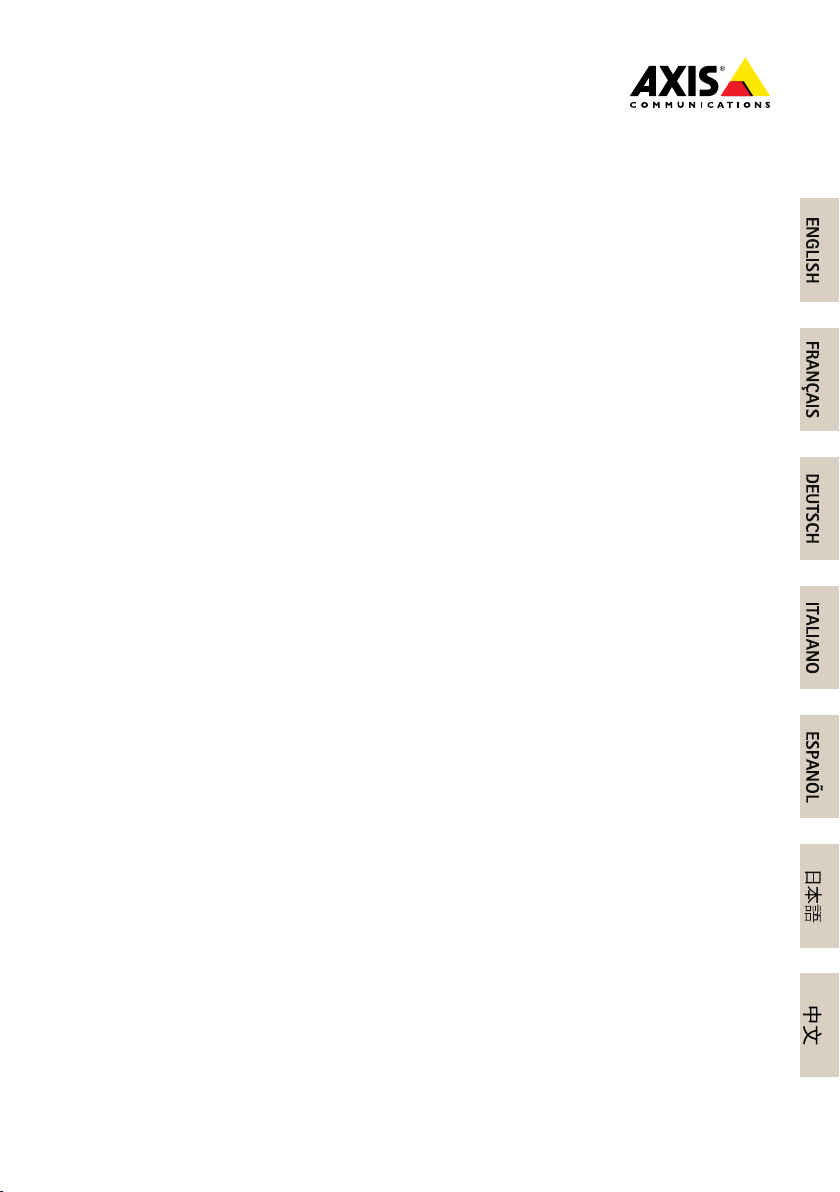
Hardwareoverview
Forspecicationsofthehardwarecomponents,seeTechnicalspecicationsonpage24.
NO
TICE
NO NO
TICE TICE
Makesurethedomeisattachedinoperationmode,otherwisefocusmaybeaffected.
Topview
1
Alignmentindicator
2
Multiconnector
3
Hookforsafetywire
4
Unitholder(3x)
5
Dome
6
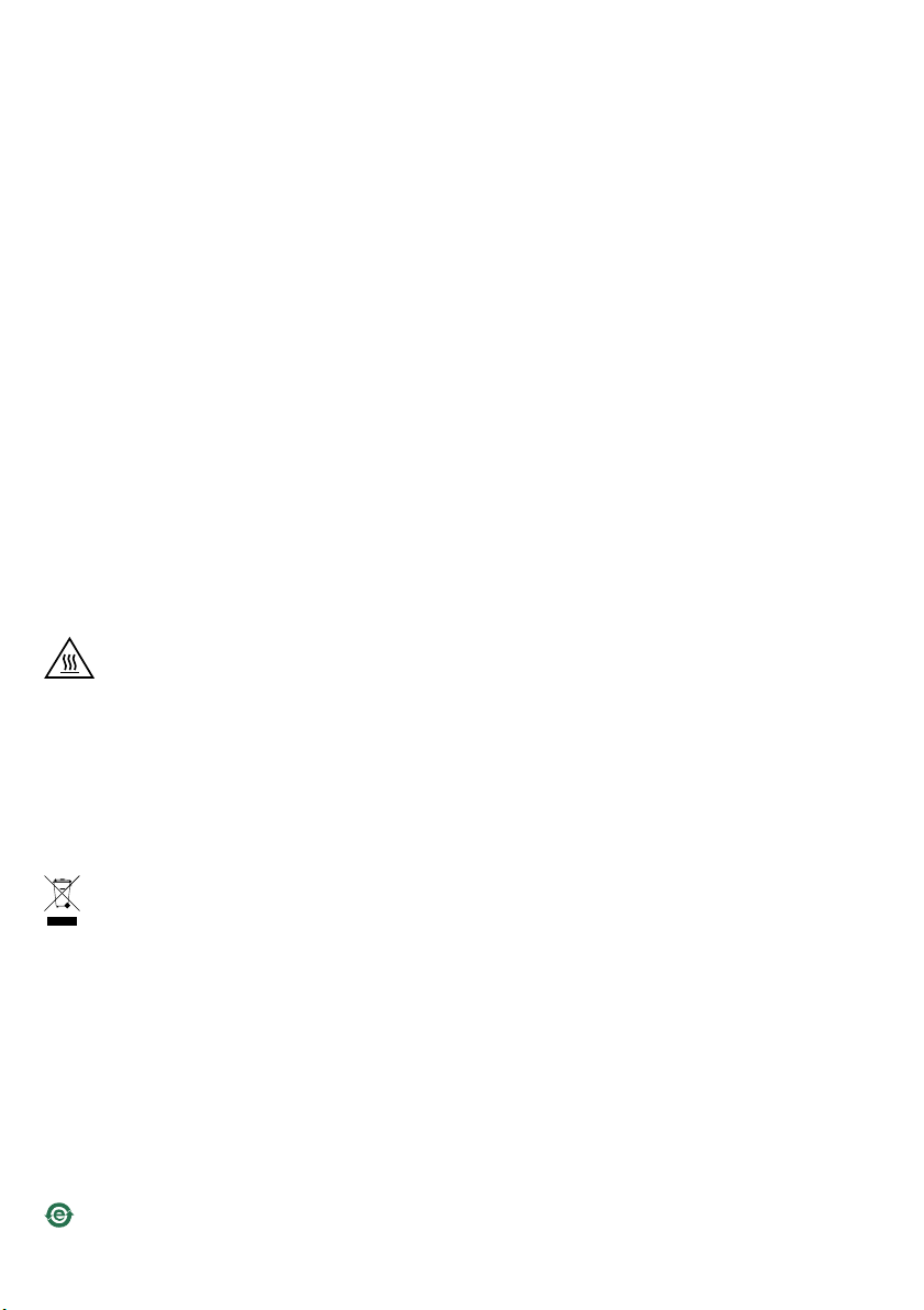
AXISQ6055-CPTZDomeNetworkCamera
Bottomview
1
Coolingsystem
2
Fan
3
SDcardslot(SDHC)
4
Controlbutton
5
Powerbutton(forFactoryDefaultonly)
6
StatusLEDindicator
7
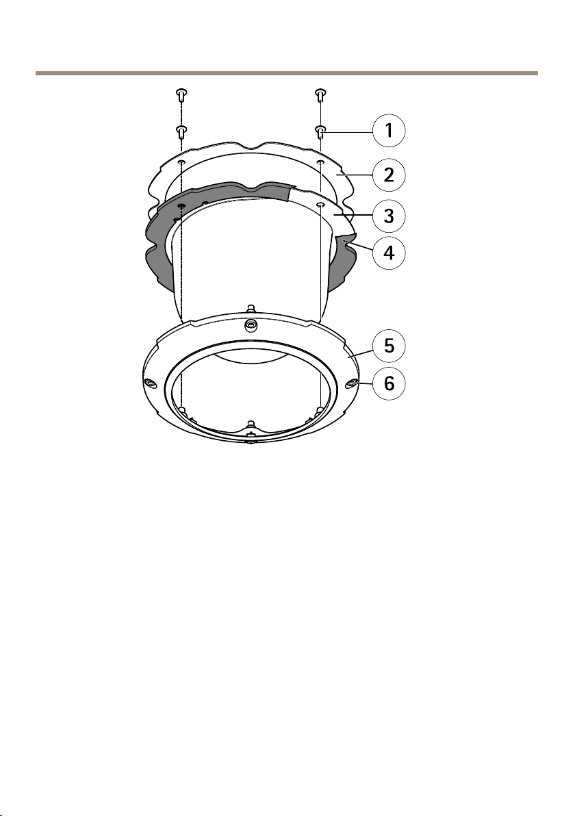
AXISQ6055-CPTZDomeNetworkCamera
1
DomebracketscrewPH2(4x)
2
Domebracket
3
Domecover
4
Rubbergasket
5
Domering
6
DomeringscrewT30(4x)
8
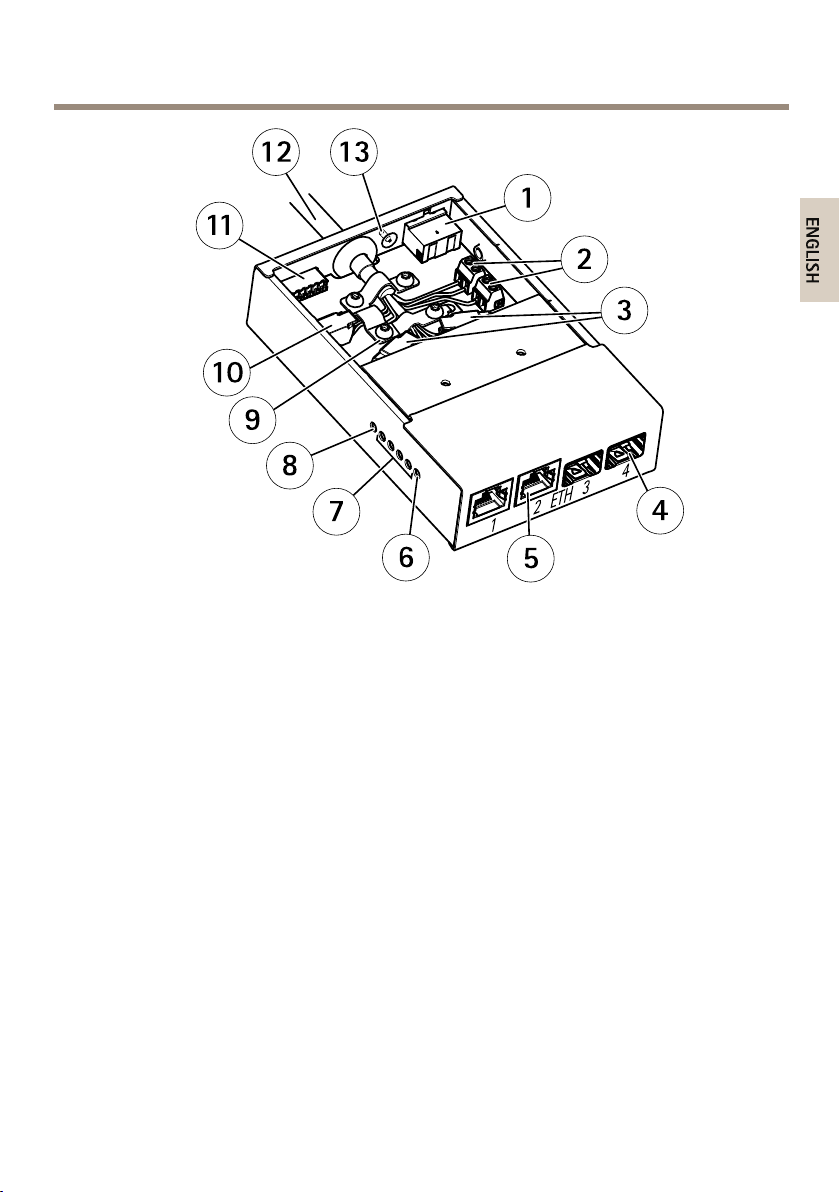
AXISQ6055-CPTZDomeNetworkCamera
1
Powerconnector(DCinput)
2
Powerconnector(DCoutput)
3
Networkconnector(internal)
4
NetworkconnectorSFP(external)(2x)
5
NetworkconnectorRJ45(external)(2x)
6
CameranetworkLEDindicator
7
NetworkLEDindicator(4x)
8
PowerLEDindicator
9
Groundclip
10
I/Oconnector(internal)
11
I/Oconnector(external)
12
Multicable
13
Groundscrew
9

AXISQ6055-CPTZDomeNetworkCamera
Howtoinstalltheproduct
Readalltheinstructionsbeforeinstallingtheproduct.Someinstallationstepswouldbenetfrom
beingcompletedtogetherbecausetheyrequireremovalofthedomecover.
NO
TICE
NO NO
TICE TICE
•Duetolocalregulationsortheenvironmentalandelectricalconditionsinwhichthe
productistobeused,ashieldednetworkcable(STP)maybeappropriateorrequired.
Allcablesconnectingtheproducttothenetworkandthatareroutedoutdoorsorin
demandingelectricalenvironmentsshallbeintendedfortheirspecicuse.Makesurethat
thenetworkdevicesareinstalledinaccordancewiththemanufacturer’sinstructions.For
informationaboutregulatoryrequirements,seeRegulatoryinformation2.
•Mounttheproductwiththedomecoverfacingdownward.
•Theproducthasadehumidifyingmembraneformaintaininglowhumiditylevelsinsidethe
dome.Toavoidcondensation,donotdisassembletheproductinrainordampconditions.
•Becarefulnottoscratch,damageorleavengerprintsonthedomecoverbecausethis
coulddecreaseimagequality.Ifpossible,keeptheprotectiveplasticonthedomecover
untiltheinstallationiscomplete.
Theproductcanbemountedwiththecablesroutedthroughoralongthewallorroof.
Recommendedtools
•Wirestrippingtool(cableconnecting)
•PhilipsscrewdriverPH2(domereplacement)
•Torx®screwdriverT20(cleaningoftheouterheatsinkwhennecessary)
•Torx®screwdriverT30(domecoverremoval,bracketadapterAXIST91A,dome
replacement)
•Torx®screwdriverT10(lid,cableclampingMediaConverterSwitch)
•Slottedscrewdriver2.5mm(socket,MediaConverterSwitch)
•7mmwrench(groundscrewMediaConverterSwitch)
•Cableshoepliers(groundcableMediaConverterSwitch)
•Diagonalpliers(cables)
Howtoreplacethedomecover(optional)
Thepremountedcleardomecovercanbereplacedifyouwanttouseasmokeddomecoverorifthe
domecoverisscratchedordamaged.Smokeddomecoversandsparecleardomecoverscanbe
purchasedfromyourAxisreseller.
1.Loosenthedomeringscrewsandremovethedomecover.
10

AXISQ6055-CPTZDomeNetworkCamera
2.Removethedomebracketscrewsandremovethedomebracketandthedomecover
fromthedomering.
3.Makesuretherubbergasketisttedcorrectlyonthedomecover.
4.Alignthebulgeonthedomecoverwithoneofthelogotypesonthedomering.
5.Attachthedomebracketandthedomecovertothedomeringandtightenthescrews
(torque1.2Nm).
6.ToinstallanSDcard,seeHowtoinstallanSDcard(optional)onpage1 1.
7.Toattachthedomecovertothetopcover,alignthebulgeonthedomecoverwiththe
coolingsystemonthecameraunitandtightenthescrews(torque1.5Nm).
1
Domecover
2
Topcover
3
Coolingsystem
HowtoinstallanSDcard(optional)
InstallinganSDcardisoptional.AstandardorhighcapacitySDcard(notincluded)canbeusedto
storerecordingslocallyintheproduct.
1.Loosenthedomeringscrewsandremovethedomecover.
11
AXISQ6055-CPTZDomeNetworkCamera
2.InsertanSDcardintotheSDcardslot.
3.Toattachthedomecovertothetopcover,alignthebulgeonthedomecoverwiththe
heateronthecameraunitandtightenthescrews(torque1.5Nm).
HowtoinstallAXIST8607MediaConverterSwitch
Thesuppliedmediaconverterswitchenablesthemulticabletosendpowerfromthepowersupply
(soldseparately)andtosendandreceivedatatoandfromexternalalarmdevicesandthenetwork.
NO
TICE
NO NO
TICE TICE
•Makesuretheconnectionstothemainssupplyandconduitshavebeeninstalledbya
trainedprofessional,accordingtothemanufacturer’sinstructionsandincompliance
withlocalregulations.
•Thepowersupply(soldseparately)andthemediaconverterswitchshallbeinstalledinan
environmentprotectedagainstdustandwater,forexampleindoorsorinanappropriate
cabinet.
Important
Axiscanonlyguaranteefullfunctionalitywiththesuppliedmediaconverterswitch.No
otherdevicesaresupported.
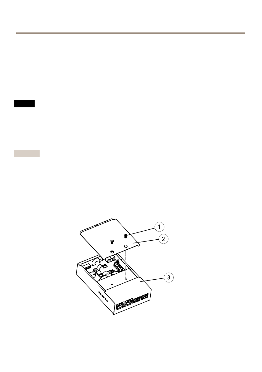
1.Makesurethemainssupplyisswitchedoff.
2.Mountthepowersupplyandthemediaconverterswitchonthewallor,ifapplicable,
attachthemtoaDINrailinthecabinet.Ifdrillingisrequired,makesuretousedrillbits,
screws,andplugsthatareappropriateforthematerial.
3.Loosenthescrewsandremovethecoverfromthemediaconverterswitch.
1
Screw(2x)
2
Cover
12
AXISQ6055-CPTZDomeNetworkCamera
3
Mediaconverterswitch
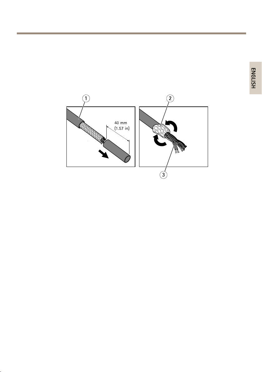
4.Stripoff40mm(1.57in)ofthemulticablejacket.
5.Leavethebraidedshieldintactandfoldbackthebraidedshield.
6.Cutoffabout7–8mm(0.27–0.32in)oftheEthernetwirefoilshields.
7.Stripoffabout4–5mm(0.16–0.20in)ofthepowerwirejackets.
1
Multicablejacket
2
Braidedshield
3
Ethernetwirefoilshield(2x)
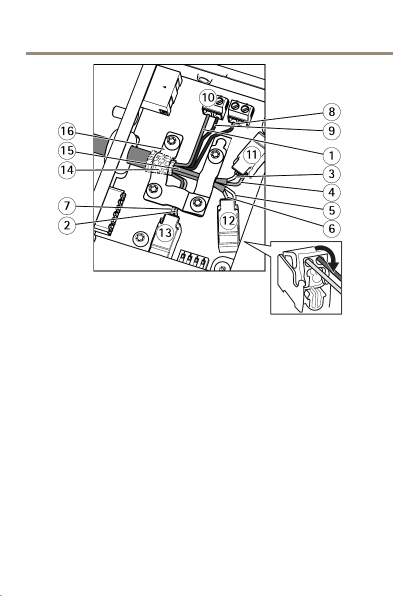
8.ConnectthenetworkandI/OwirestotheinternalnetworkandI/Oconnectors.Open
thelid,insertthewiresandclose.
9.Connectthegroundandpowerwirestothepowerconnector(DCoutput).
13
AXISQ6055-CPTZDomeNetworkCamera
1
Powerwire(red)
2
DigitalI/Owire(blue)
3
Ethernetwire(green/white)
4
Ethernetwire(green)
5
Ethernetwire(orange/white)
6
Ethernetwire(orange)
7
DigitalI/Owire(yellow)
8
Groundwire(black)
9
Powerwire(red)
10
Powerconnector(DCoutput)
11
Ethernetconnector(internal)
12
Ethernetconnector(internal)
13
I/Oconnector(internal)
14
Braidedshieldcoil
15
Ethernetwireshield(2x)
16
Clamp
10.Makesuretheclampisinplace,insertthebraidedshieldcoilintothegroundclipand
tightenthescrews.
14
AXISQ6055-CPTZDomeNetworkCamera
NO
TICE
NO NO
TICE TICE
•Theshieldsandtheclampsurfacesshallbeinfullcontactwitheachothersothatthe
multicableisgrounded.
•Makesurethatthemulticablejacketisrmlysecuredbytheclamp.
•Makesureallsurfacesandcontactsarecleanandfreefromscrapshieldmaterial.
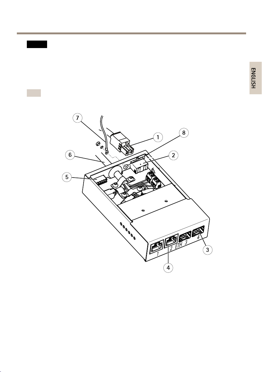
11.Connectthenetworkcablestotheexternalnetworkconnectors(RJ45,SFP)asrequired.
Note
AnSFPmodule(notincluded)hastobeusedwhenconnectinganopticalbercable.
1
Powercable(DCinput)
2
Powerconnector(DCinput)
3
NetworkconnectorSFP(external)(2x)
4
NetworkconnectorRJ45(external)(2x)
5
I/Oconnector(external)
6
MulticableIP66
7
Groundwire
8
Groundscrew
15
AXISQ6055-CPTZDomeNetworkCamera
12.Ifapplicable,connectanI/OdevicetotheexternalI/Oconnector.
13.Connectthepowercable(DCinput)tothepowerconnector(DCinput)viatheterminal
blockplug.
14.Attachthegroundwiretothegroundscrew.
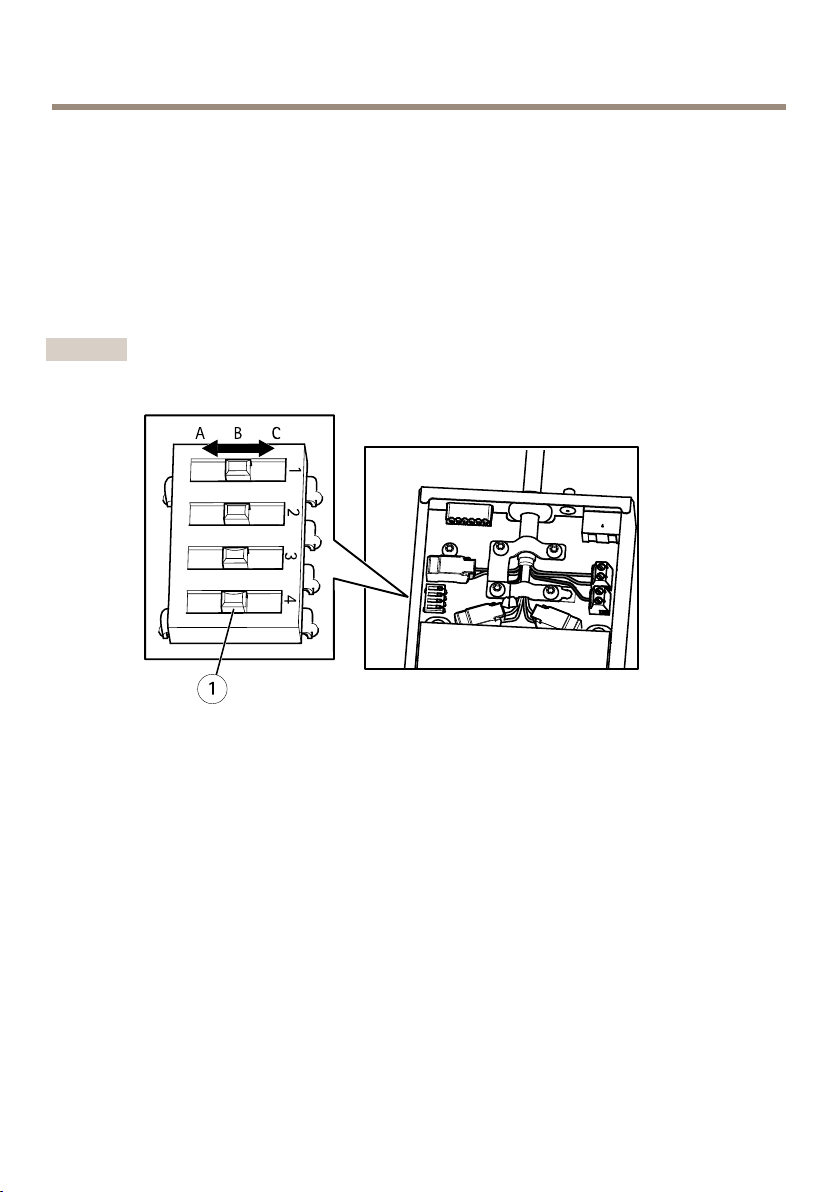
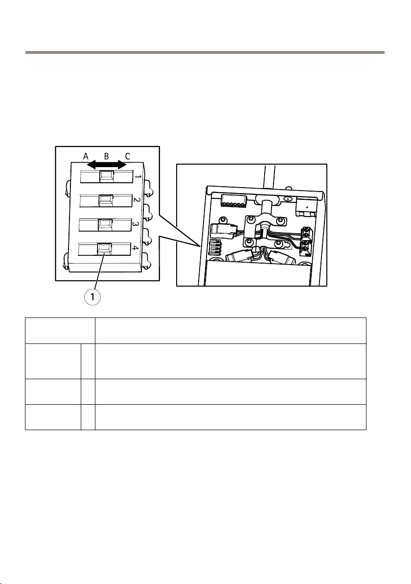
15.Ifconnectingseveralmediaconverterswitchesinadaisychain,setthedipswitchof
eachoutgoingnetworkconnectorportthatconnectstoanothermediaconverterswitch
topositionC.
Leavethedipswitchinitsdefaultposition(positionB)whenconnectingtheportdirectly
tothenetwork.Formoreinformation,seeMediaconverterswitchconnectorsonpage27.
Important
Ifthesystemisnotdened,usethedefaultdipswitchsetting(positionB).
1
Dipswitch(4x)
16.Attachthecovertothemediaconverterswitch.
17.Switchonthemainssupply.
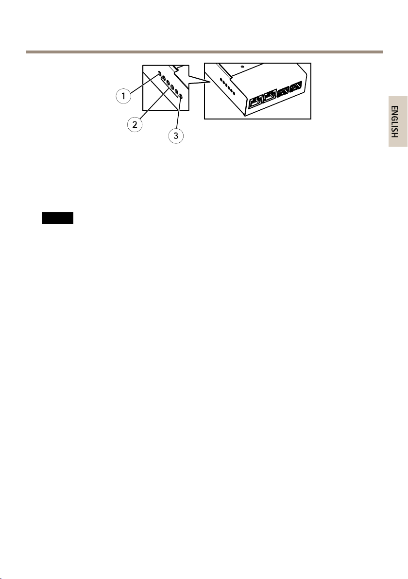
18.MakesuretheLEDindicatorsonthemediaconverterswitchindicatethecorrect
conditions.Formoreinformation,seeMediaconverterswitchLEDindicatorsonpage24.
16
AXISQ6055-CPTZDomeNetworkCamera
1
PowerLEDindicator
2
NetworkLEDindicator(4x)ETH1/2/3/4
3
CameraLEDindicator
Howtoinstallthenetworkcamera
NO
TICE
NO NO
TICE TICE
TocomplywiththeIP66-rateddesignofthecameraandmaintaintheIP66protection,the
suppliedmulticonnectorcableshallbeused.
Removetheprotectivepackagingbetweenthecameraandthesunshieldbeforeinstallingthe
camera.
1.Installtheselectedbracketaccordingtotheinstructionssuppliedwiththebracket.If
drillingisrequired,makesuretousedrillbits,screws,andplugsthatareappropriatefor
thematerial.
2.Routethemulticablethroughtheholesinthemountingbracket.
3.Securethecamerausingthesuppliedsafetywire.
17
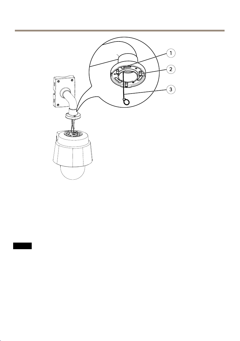
AXISQ6055-CPTZDomeNetworkCamera
Mountingexample(wallbracketsoldseparately)
1
Slotforunitholders(3x)
2
ScrewT30(2x)
3
Safetywire
4.Removetheprotectioncapcoveringthemulticonnectoronthecamera.
5.Connectthemulticabletotheconnectoronthecamera.Usethealignmentindicatorsto
ndthecorrectposition.
NO
TICE
NO NO
TICE TICE
Becarefulnotdodamagethemulticablewhenconnectingit.
18
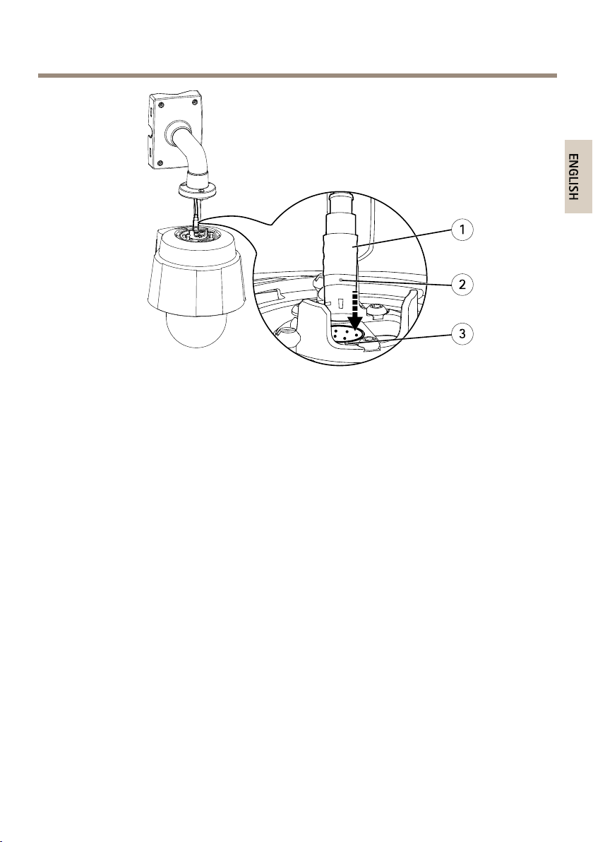
AXISQ6055-CPTZDomeNetworkCamera
Mountingexample(wallbracketsoldseparately)
1
Multicable
2
Alignmentindicator–multicable
3
Alignmentindicator–camera
6.Slidetheunitholdersonthecameraintotheslotsinthemountingbracketandrotate
thecameraunit.
7.Securethenetworkcameratothemountingbracketbytighteningthescrews.
Howtoaccesstheproduct
AXISIPUtilityandAXISCameraManagementarerecommendedmethodsforndingAxisproducts
onthenetworkandassigningthemIPaddressesinWindows®.Bothapplicationsarefreeandcan
bedownloadedfromwww.axis.com/techsup
Theproductcanbeusedwithmostoperatingsystemsandbrowsers.Werecommendthefollowing
browsers:
•InternetExplorer
•Safari
•Chrome
®
withOSX
TM
®
withWindows
®
orFirefox
®
withotheroperatingsystems.
Formoreinformationaboutusingtheproduct,seetheUserManualavailableatwww.axis.com
®
19

AXISQ6055-CPTZDomeNetworkCamera
Howtoresettofactorydefaultsettings
Important
Resettofactorydefaultshouldbeusedwithcaution.Aresettofactorydefaultwillreset
allsettings,includingtheIPaddress,tothefactorydefaultvalues.
Note
Theinstallationandmanagementsoftwaretoolsareavailablefromthesupportpages
onwww.axis.com/techsup
Toresettheproducttothefactorydefaultsettings:
1.Pressandholdthecontrolbuttonandthepowerbuttonfor15–30secondsuntilthe
statusLEDindicatorashesamber.SeeHardwareoverviewonpage6.
2.Releasethecontrolbuttonbutcontinuetoholddownthepowerbuttonuntilthestatus
LEDindicatorturnsgreen.
3.Releasethepowerbuttonandassembletheproduct.
4.Theprocessisnowcomplete.Theproducthasbeenresettothefactorydefaultsettings.
IfnoDHCPserverisavailableonthenetwork,thedefaultIPaddressis192.168.0.90
5.Usingtheinstallationandmanagementsoftwaretools,assignanIPaddress,setthe
passwordandaccessthevideostream.
Itisalsopossibletoresetparameterstofactorydefaultviathewebinterface.GotoSetup>
SystemOptions>MaintenanceandclickDefault.
20
AXISQ6055-CPTZDomeNetworkCamera
Maintenance
Howtocleantheouterheatsink
Dustandparticlebuildupcouldaffecttheperformanceofthecoolingsystem.Tomaintainthe
performancelevel,theouterheatsinkinthecamera’scoolingsystemmayneedoccasionalor
regularcleaning.
CAUTION
Theheatsinkcouldbehot.Becarefulwhentouchingtheheatsinkandtheheatsinkcover.
Ifrequired,letthecameracoolbeforetouchingit.
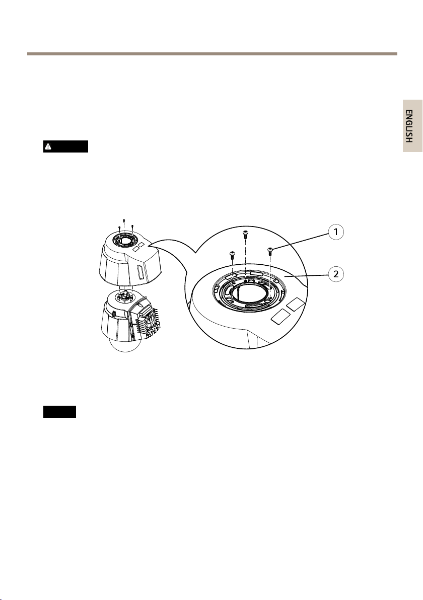
1.Disconnectthemulticable.
2.Loosenthescrewsandremovethesunshield.
1
ScrewT20(3x)
2
Sunshield
3.Removethescrews(TorxT30)andlifttheheatsinkcover.
NO
TICE
NO NO
TICE TICE
Donotstrainthefancablesorlettheheatsinkcoverhangbythefancables.
21
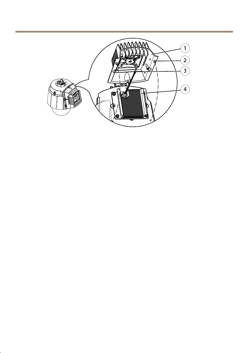
AXISQ6055-CPTZDomeNetworkCamera
1
Heatsinkcover
2
ScrewT30(3x)
3
Fancables
4
Heatsink
4.Removedustandspecksofdirtbyblowingontheheatsink,forexamplebyusinga
smallaircompressororacanofcompressedair.Theheatsinkmayalsoberinsedwith
purewater.
5.Puttheheatsinkcoverbackinitsoriginalpositionandtightenthescrews(torque
2.4±0.2Nm).
6.Putthesunshieldbackinitsoriginalpositionandtightenthescrews(torque1.2±0.1Nm).
7.Connectthemulticabletotheconnectoronthecamera.
22

AXISQ6055-CPTZDomeNetworkCamera
Furtherinformation
•Forthelatestversionofthisdocument,seewww.axis.com
•Theusermanualisavailableatwww.axis.com
•Tocheckifthereisupdatedrmwareavailableforyourproduct,see
www.axis.com/support
•Forusefulonlinetrainingsandwebinars,seewww.axis.com/academy
Optionalaccessories
Foracompletelistofavailableaccessoriesforthisproduct,gotowww.axis.com
23

AXISQ6055-CPTZDomeNetworkCamera
Technicalspecifications
Youcanndthelatestversionofthetechnicalspecicationsatwww.axis.com
LEDIndicators
StatusLED
Unlit
GreenShowssteadygreenfor10secondsfornormaloperationafter
Amber
Amber/RedFlashesamber/redifnetworkconnectionisunavailableorlost.
RedFirmwareupgradefailure.
Indication
Connectionandnormaloperation.
startupcompleted.
Steadyduringstartup.Flashesduringrmwareupgradeorreset
tofactorydefault.
MediaconverterswitchLEDindicators
LED
Power
Network(4x)
Camera
network(only
availableon
AXIST8607)
Color
Unlit
GreenDCpowerconnected.
Amber10Mbitconnection.Flashesduringactivity.
Green
Green
Indication
DCpowerunconnectedorcurrentprotectionengaged(power
overload)
100/1000Mbitconnection.Flashesduringactivity.
100Mbitconnection.Flashesduringactivity.
SDcardslot
NO
TICE
NO NO
TICE TICE
•RiskofdamagetoSDcard.Donotusesharptools,metalobjectsorexcessiveforcewhen
insertingorremovingtheSDcard.Useyourngerstoinsertandremovethecard.
•Riskofdatalossandcorruptedrecordings.DonotremovetheSDcardwhiletheproduct
isrunning.DisconnectpowerorunmounttheSDcardfromtheAxisproduct’swebpages
beforeremoval.
24

AXISQ6055-CPTZDomeNetworkCamera
ThisproductsupportsSD/SDHC/SDXCcards(notincluded).
ForSDcardrecommendations,seewww.axis.com
Buttons
ControlButton
Forlocationofthecontrolbutton,seeHardwareoverviewonpage6.
Thecontrolbuttonisusedfor:
•Resettingtheproducttofactorydefaultsettings.Seepage20.
•ConnectingtoanAXISVideoHostingSystemserviceorAXISInternetDynamicDNS
Service.Formoreinformationabouttheseservices,seetheUserManual.
Powerbutton
Pressandholdthepowerbuttontotemporarilypowertheproductwhenthedomecoveris
removed.Thepowerbuttonisalsousedwiththecontrolbuttontoresetthecameratofactory
defaultsettings.Seepage20.
Connectors
Multiconnector
Terminalconnectorforconnectingthesuppliedmediaconverterswitch,whichprovidesthe
followingsignals:
•DCPower
•Network(Ethernet10/100Base-T)
•Input/Output(I/O)
Multicableconnectors
Note
Thesuppliedmulticableisrequiredinordertomaintainthecamera’sNEMA/IPrating.
Themulticableisconnectedtothecamera’smulticonnector,seeHardwareoverviewonpage6.
Thewiresareconnectedtothesuppliedmediaconverterswitch,seeAXIST8607MediaConverter
Switchonpage8.
Thecableprovidesthefollowingsignals:
25
AXISQ6055-CPTZDomeNetworkCamera
•DCpowertocamera
•Network(Ethernet10/100Base-T)
•Input/Output(I/O)
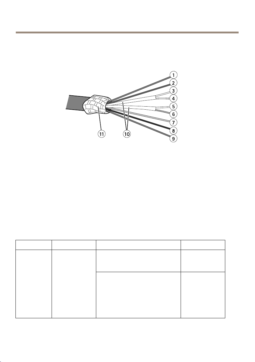
Multicableoverview
1
Powerwire(red)
2
DigitalI/Owire(blue)
3
Ethernetwire(green/white)
4
Ethernetwire(green)
5
Ethernetwire(orange/white)
6
Ethernetwire(orange)
7
DigitalI/Owire(yellow)
8
Groundwire(black)
9
Powerwire(red)
10
Ethernetwirefoilshield(2x)
11
Braidedshieldcoil
FunctionPin–wireNotes
Congurable
(Inputor
Output)
2–blue
7–yellow
Digitalinput–Connecttopin
8toactivate,orleaveoating
(unconnected)todeactivate.
Digitaloutput–Connectedto
pin1whenactivated,oating
(unconnected)whendeactivated.If
usedwithaninductiveload,e.g.a
relay,adiodemustbeconnectedin
parallelwiththeload,forprotection
againstvoltagetransients.
26
Specications
0tomax30VDC
0tomax30VDC,
opendrain,
100mA
AXISQ6055-CPTZDomeNetworkCamera
RX+
RXTX+
TX-
0VDC(-)
DCoutput
(24V)
3–green/white
4–green
5–orange/white
6–orange
8–black
1,9–redUsedtopowercamera
Ethernet–receiving
Ethernet–receiving
Ethernet–transmitting
Ethernet–transmitting
Mediaconverterswitchconnectors
NO
TICE
NO NO
TICE TICE
Theproductshallbeconnectedusingashieldednetworkcable(STP)oranopticalber
cable.Allcablesconnectingtheproducttothenetworkshallbeintendedfortheir
specicuse.Makesurethatthenetworkdevicesareinstalledinaccordancewith
themanufacturer’sinstructions.Forinformationaboutregulatoryrequirements,see
Electromagneticcompatibility(EMC)2.
Important
Themediaconverterswitchdoesnotsupporthotswapping.Disconnectpowerfromthe
switchbeforeswappingcameras.Anattempttohotswapcouldcausetheswitchtofreeze,
inwhichcaseitmustberestarted.
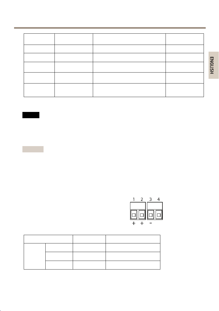
Cameraconnectors
0VDC
24VDC
Powerconnector
Two2-pinterminalblocksforpoweroutput(pin4
isnotused).
FunctionPinNotes
DC
output
24VDC
0VDC(-)
N/A
1,2
3
4
Powerouttocamera
N/A
27
AXISQ6055-CPTZDomeNetworkCamera
Networkconnector
Two2-pinEthernetterminalblocks.
I/Oterminalconnector
2-pinterminalblock.
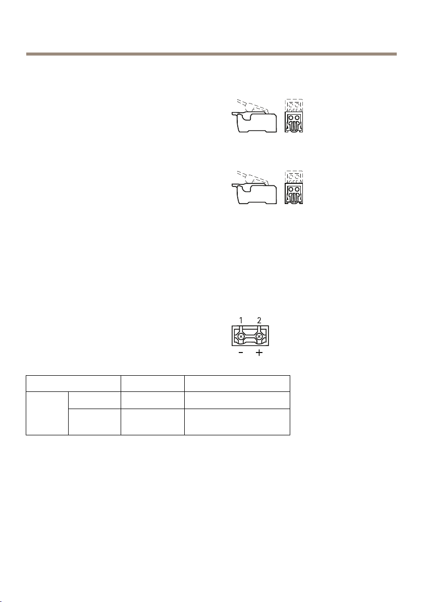
Externalconnectors
GroundscrewGroundscrewforconnectingthemedia
Powerconnector
2-pinterminalblockforpowerinput.
FunctionPinNotes
DCinput
NetworkconnectorRJ45
NetworkslotSFP
0VDC(-)
24VDC
1
2
Powerinfrompower
supply(soldseparately)
converterswitchtoearthground.Make
surethatbothendsofthegrounding
wireareincontactwiththeirrespective
groundingsurfaces.
TwoRJ45connectors(10/100Base-T)for
network.
TwoSFPslots(100Base-FX/1000Base-X)for
network.
28
AXISQ6055-CPTZDomeNetworkCamera
EachRJ45andSFPporthasitsowndipswitch.Thedipswitchescontrolhowtheportforwards
data.Formoreinformation,seepage29.
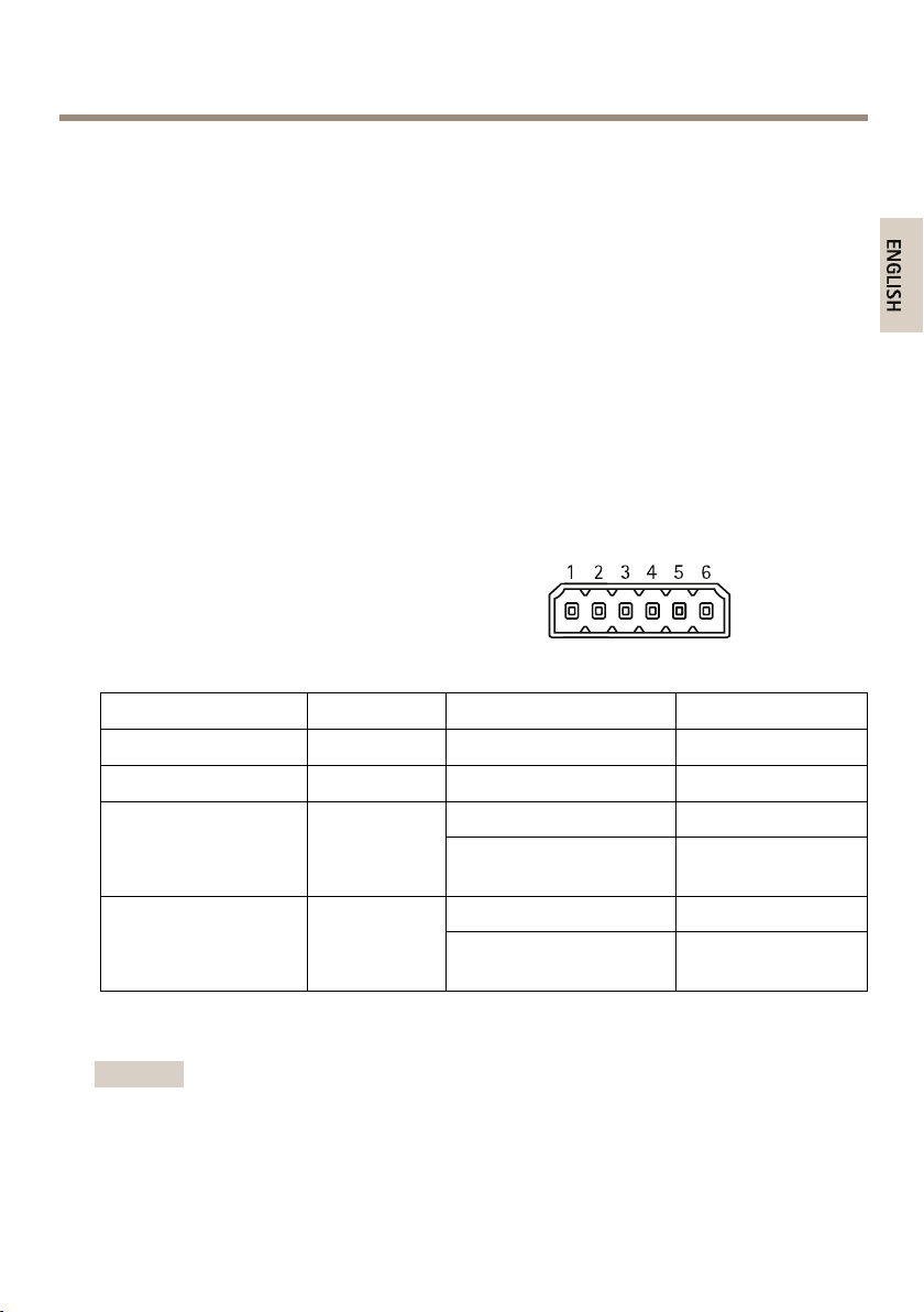
I/Oterminalconnector
6-pincongurableI/Oterminalblock,whichisconnectedtothecamerathroughthemulticable.
Usewithexternaldevicesincombinationwith,forexample,tamperingalarms,motiondetection,
eventtriggering,timelapserecordingandalarmnotications.Inadditiontothe0VDC
referencepointandpower(DCoutput),theI/Oconnectorprovidestheinterfaceto:
•Digitaloutput–ForconnectingexternaldevicessuchasrelaysandLEDs.Connected
devicescanbeactivatedbytheVAPIX®ApplicationProgrammingInterface,output
buttonsontheLiveViewpageorbyanActionRule.Theoutputwillshowasactive
(shownunderSystemOptions>Port&Devices>PortStatus)ifthealarmdevice
isactivated.
•Digitalinput–Analarminputforconnectingdevicesthatcantogglebetween
anopenandclosedcircuit,forexample:PIRs,door/windowcontacts,glassbreak
detectors,etc.Whenasignalisreceivedthestatechangesandtheinputbecomes
active(shownunderSystemOptions>Port&Devices>PortStatus).
6-pinterminalblocksfor:
•DigitalInput/Output
•Power(DCoutput)
•0VDC(-)
FunctionPinNotes
0VDC(-)
DCoutput
Congurable
I/O1(InputorOutput)
Congurable
I/O2(InputorOutput)
Networkconnectordipswitches
Important
Alwaysusethedefaultdipswitchsetting(positionB)iftherelationshipbetweendevicesin
thesystemisnotdened.
1,4,6
2
3
5
Powerout
Digitalinput
Digitaloutput(transistor–
opencollector)
Digitalinput
Digitaloutput(transistor–
opencollector)
Specications
0VDC
12VDC,50mA
0tomax30VDC
0tomax30VDC,
opendrain,100mA
0tomax30VDC
0tomax30VDC,
opendrain,100mA
29
AXISQ6055-CPTZDomeNetworkCamera
ThecameraattachesaparticularVLANtagtoallitsforwardedmulticastpackages.Themedia
converterswitchmanageshowthesemulticastpackagesareforwardedbetweencameras,media
converterswitchesandothernetworkdevices.Thisespeciallyusefulwhenconnectingthecamera
andmediaconverterswitchtothenetworkinadaisychain.
Bychangingthepositionofthedipswitches,eachnetworkconnectorportinthemediaconverter
switchcanbeconguredtomanagemulticastsinthreedifferentways.
Dipswitch
position
Default
(middle)
LeftABlockmulticastpackagesthathaveaVLANtag.Usethissettingwhen
Right
VLANtagsareusedtocreateindependentlogicalnetworks,virtuallocalareanetworks(VLANs),
withinaphysicalnetwork.Multiplemediaconverterswitchesthatareconnectedtoeachother
inadaisychainaremembersofthesameVLAN.Themediaconverterswitchestagthemulticast
packagesmovingbetweenthemsothatthenextmediaconverterswitchinlineknowsthe
destinationofthepackages.Inotherwords,theVLANtagservesasaVLANidentier.VLAN
taggingshouldonlybeusedwhenusingmultiplecamerasandmediaconverterswitchesbecause
forwardingmulticastpackageswithaVLANtagonlyservesapurposewhentheportisconnected
toanothermediaconverterswitch,whichmightbeconnectedtopotentialviewers.
Description
BRemoveVLANtagsfromforwardedmulticastpackages.Usethissetting
whenconnectingtothenetwork,directlyorthrougharouterornetwork
switch.
connectingtoadevicethatisnotintendedformulticastviewing.
ForwardmulticastpackageswithaVLANtag.Usethissettingwhen
C
connectingtoanothermediaconverterswitch.
30
 Loading...