

Page 1

AXIS Q6045-C Mk II PTZ Dome Network Camera
User Manual
Page 2

About this Document
This manual is intended for administrators and users of the
AXIS Q6045-C Mk II PTZ Dome Network Camera, and is applicable to
rmware 5.55 and later. It includes instructions for using and managing
the product on your network. Previous experience of networking
will be of use when using this product. Some knowledge of UNIX or
Linux-based systems may also be benecial, for developing shell scripts
and applications. Later versions of this document will be posted to the
Axis website, as required. See also the product’s online help, available
via the web-based interface.
Legal Considerations
Video surveillance can be regulated by laws that vary from country to
country. Check the laws in your local region before using this product
for surveillance purposes.
This product includes one (1) H.264 decoder license. To purchase
further licenses, contact your reseller.
Liability
Every care has been taken in the preparation of this document. Please
inform your local Axis ofce of any inaccuracies or omissions. Axis
Communications AB cannot be held responsible for any technical or
typographical errors and reserves the right to make changes to the
product and manuals without prior notice. Axis Communications AB
makes no warranty of any kind with regard to the material contained
within this document, including, but not limited to, the implied
warranties of merchantability and tness for a particular purpose. Axis
Communications AB shall not be liable nor responsible for incidental or
consequential damages in connection with the furnishing, performance
or use of this material. This product is only to be used for its intended
purpose.
Intellectual Property Rights
Axis AB has intellectual property rights relating to technology embodied
in the product described in this document. In particular, and without
limitation, these intellectual property rights may include one or more
of the patents listed at www.axis.com/patent.htm and one or more
additional patents or pending patent applications in the US and other
countries.
This product contains licensed third-party software. See the menu item
“About” in the product’s user interface for more information.
This product contains source code copyright Apple Computer,
Inc., under the terms of Apple Public Source License 2.0 (see
www.opensource.apple.com/apsl). The source code is available from
https://developer.apple.com/bonjour/
Equipment Modications
This equipment must be installed and used in strict accordance with the
instructions given in the user documentation. This equipment contains
no user-serviceable components. Unauthorized equipment changes or
modications will invalidate all applicable regulatory certications
and approvals.
Trademark Acknowledgments
AXIS COMMUNICATIONS, AXIS, ETRAX, ARTPEC and VAPIX are
registered trademarks or trademark applications of Axis AB in various
jurisdictions. All other company names and products are trademarks or
registered trademarks of their respective companies.
Apple, Boa, Apache, Bonjour, Ethernet, Internet Explorer, Linux,
Microsoft, Mozilla, Real, SMPTE, QuickTime, UNIX, Windows, Windows
Vista and WWW are registered trademarks of the respective holders.
Java and all Java-based trademarks and logos are trademarks or
registered trademarks of Oracle and/or its afliates. UPnPTMis a
certication mark of the UPnPTMImplementers Corporation.
SD, SDHC and SDXC are trademarks or registered trademarks of SD-3C,
LLC in the United States, other countries or both. Also, miniSD, microSD,
miniSDHC, microSDHC, microSDXC are all trademarks or registered
trademarks of SD-3C, LLC in the United States, other countries or both.
Regulatory Information
Europe
This product complies with the applicable CE marking directives
and harmonized standards:
• Electromagnetic Compatibility (EMC) Directive 2004/108/EC. See
Electromagnetic Compatibility (EMC) on page 2 .
• Low Voltage (LVD) Directive 2006/95/EC. See Safety on page 2 .
• Restrictions of Hazardous Substances (RoHS) Directive 2011/65/EU.
See Disposal and Recycling on page 3 .
A copy of the original declaration of conformity may be obtained from
Axis Communications AB. See Contact Information on page 3 .
Electromagnetic Compatibility (EMC)
This equipment has been designed and tested to fulll applicable
standards for:
• Radio frequency emission when installed according to the
instructions and used in its intended environment.
• Immunity to electrical and electromagnetic phenomena when
installed according to the instructions and used in its intended
environment.
USA
This equipment has been tested using a shielded network cable (STP)
and found to comply with the limits for a Class A digital device,
pursuant to part 15 of the FCC Rules. These limits are designed to
provide reasonable protection against harmful interference when the
equipment is operated in a commercial environment. This equipment
generates, uses, and can radiate radio frequency energy and, if not
installed and used in accordance with the instruction manual, may
cause harmful interference to radio communications. Operation of this
equipment in a residential area is likely to cause harmful interference
in which case the user will be required to correct the interference at his
own expense.
The product shall be connected using a shielded network cable (STP)
that is properly grounded.
Canada
This digital apparatus complies with CAN ICES-3 (Class A). The product
shall be connected using a shielded network cable (STP) that is properly
grounded.
Cet appareil numérique est conforme à la norme NMB ICES-3 (classe A).
Le produit doit être connecté à l'aide d'un câble réseau blindé (STP) qui
est correctement mis à la terre.
Europe
This digital equipment fullls the requirements for RF emission
according to the Class A limit of EN 55022. The product shall be
connected using a shielded network cable (STP) that is properly
grounded. Notice! This is a Class A product. In a domestic environment
this product may cause RF interference, in which case the user may be
required to take adequate measures.
This product fullls the requirements for emission and immunity
according to EN 50121-4 and IEC 62236-4 railway applications.
This product fullls the requirements for immunity according
to EN 61000-6-1 residential, commercial and light-industrial
environments.
This product fullls the requirements for immunity according to
EN 61000-6-2 industrial environments.
This product fullls the requirements for immunity according to
EN 55024 ofce and commercial environments
Australia/New Zealand
This digital equipment fullls the requirements for RF emission
according to the Class A limit of AS/NZS CISPR 22. The product shall
be connected using a shielded network cable (STP) that is properly
grounded. Notice! This is a Class A product. In a domestic environment
this product may cause RF interference, in which case the user may be
required to take adequate measures.
Japan
この装置は、クラスA情報技術装置です。この装置を家庭環
境で使用すると電波妨害を引き起こすことがあります。この
場合には使用者が適切な対策を講ずるよう要求されることが
あります。本製品は、シールドネットワークケーブル(STP)を
使用して接続してください。また適切に接地してください。
Safety
This product complies with IEC/EN/UL 60950-1 and
IEC/EN/UL 60950-22, Safety of Information Technology
Equipment. The product shall be grounded either through a shielded
network cable (STP) or other appropriate method.
The power supply used with this product shall fulll the requirements
for Safety Extra Low Voltage (SELV) according to IEC/EN/UL 60950-1.
Page 3

Disposal and Recycling
When this product has reached the end of its useful life, dispose of
it according to local laws and regulations. For information about
your nearest designated collection point, contact your local authority
responsible for waste disposal. In accordance with local legislation,
penalties may be applicable for incorrect disposal of this waste.
Europe
This symbol means that the product shall not be disposed of
together with household or commercial waste. Directive 2012/19/EU
on waste electrical and electronic equipment (WEEE) is applicable in
the European Union member states. To prevent potential harm to
human health and the environment, the product must be disposed
of in an approved and environmentally safe recycling process. For
information about your nearest designated collection point, contact
your local authority responsible for waste disposal. Businesses should
contact the product supplier for information about how to dispose
of this product correctly.
This product complies with the requirements of Directive 2011/65/EU on
the restriction of the use of certain hazardous substances in electrical
and electronic equipment (RoHS).
China
This product complies with the requirements of the legislative
act Administration on the Control of Pollution Caused by Electronic
Information Products (ACPEIP).
Contact Information
Axis Communications AB
Emdalavägen 14
223 69 Lund
Sweden
Tel: +46 46 272 18 00
Fax: +46 46 13 61 30
www.axis.com
Support
Should you require any technical assistance, please contact your Axis
reseller. If your questions cannot be answered immediately, your
reseller will forward your queries through the appropriate channels to
ensure a rapid response. If you are connected to the Internet, you can:
• download user documentation and software updates
• nd answers to resolved problems in the FAQ database. Search
by product, category, or phrase
• report problems to Axis support staff by logging in to your private
support area
• chat with Axis support staff (selected countries only)
• visit Axis Support at www.axis.com/techsup/
Learn More!
Visit Axis learning center www.axis.com/academy/ for useful trainings,
webinars, tutorials and guides.
Page 4

AXIS Q6045-C Mk II PTZ Dome Network Camera
Table of Contents
Hardware Overview . . . . . . . . . . . . . . . . . . . . . . . . . . . . . . . . . . . . . . . . . . 6
Camera . . . . . . . . . . . . . . . . . . . . . . . . . . . . . . . . . . . . . . . . . . . . . . . . . . . . . . . 6
Connectors and Buttons . . . . . . . . . . . . . . . . . . . . . . . . . . . . . . . . . . . . . . . . . . 6
LED Indicators . . . . . . . . . . . . . . . . . . . . . . . . . . . . . . . . . . . . . . . . . . . . . . . . . . 7
Media Converter Switch . . . . . . . . . . . . . . . . . . . . . . . . . . . . . . . . . . . . . . . . . . 8
Access the Product . . . . . . . . . . . . . . . . . . . . . . . . . . . . . . . . . . . . . . . . . . 11
Access from a Browser . . . . . . . . . . . . . . . . . . . . . . . . . . . . . . . . . . . . . . . . . . . 11
Access from the Internet . . . . . . . . . . . . . . . . . . . . . . . . . . . . . . . . . . . . . . . . . . 11
Set the Root Password . . . . . . . . . . . . . . . . . . . . . . . . . . . . . . . . . . . . . . . . . . . 11
The Live View Page . . . . . . . . . . . . . . . . . . . . . . . . . . . . . . . . . . . . . . . . . . . . . . 12
Media Streams . . . . . . . . . . . . . . . . . . . . . . . . . . . . . . . . . . . . . . . . . . . . . 15
How to Stream H.264 . . . . . . . . . . . . . . . . . . . . . . . . . . . . . . . . . . . . . . . . . . . . 15
MJPEG . . . . . . . . . . . . . . . . . . . . . . . . . . . . . . . . . . . . . . . . . . . . . . . . . . . . . . . . 15
AXIS Media Control (AMC) . . . . . . . . . . . . . . . . . . . . . . . . . . . . . . . . . . . . . . . . 15
Alternative Methods of Accessing the Video Stream . . . . . . . . . . . . . . . . . . . . 16
Set Up the Product . . . . . . . . . . . . . . . . . . . . . . . . . . . . . . . . . . . . . . . . . . 18
Basic Setup . . . . . . . . . . . . . . . . . . . . . . . . . . . . . . . . . . . . . . . . . . . . . . . . . . . . 18
Video . . . . . . . . . . . . . . . . . . . . . . . . . . . . . . . . . . . . . . . . . . . . . . . . . . . . . 19
Video Stream . . . . . . . . . . . . . . . . . . . . . . . . . . . . . . . . . . . . . . . . . . . . . . . . . . . 19
Stream Proles . . . . . . . . . . . . . . . . . . . . . . . . . . . . . . . . . . . . . . . . . . . . . . . . . 20
Camera Settings . . . . . . . . . . . . . . . . . . . . . . . . . . . . . . . . . . . . . . . . . . . . . . . . 21
Overlay . . . . . . . . . . . . . . . . . . . . . . . . . . . . . . . . . . . . . . . . . . . . . . . . . . . . . . . . 22
Privacy Mask . . . . . . . . . . . . . . . . . . . . . . . . . . . . . . . . . . . . . . . . . . . . . . . . . . . 24
Congure the Live View Page . . . . . . . . . . . . . . . . . . . . . . . . . . . . . . . . . 25
PTZ (Pan Tilt Zoom) . . . . . . . . . . . . . . . . . . . . . . . . . . . . . . . . . . . . . . . . . 27
Preset Positions . . . . . . . . . . . . . . . . . . . . . . . . . . . . . . . . . . . . . . . . . . . . . . . . . 27
Gatekeeper . . . . . . . . . . . . . . . . . . . . . . . . . . . . . . . . . . . . . . . . . . . . . . . . . . . . 28
Autotracking . . . . . . . . . . . . . . . . . . . . . . . . . . . . . . . . . . . . . . . . . . . . . . . . . . . 28
Guard Tour . . . . . . . . . . . . . . . . . . . . . . . . . . . . . . . . . . . . . . . . . . . . . . . . . . . . . 29
OSDI Zones . . . . . . . . . . . . . . . . . . . . . . . . . . . . . . . . . . . . . . . . . . . . . . . . . . . . 30
Advanced . . . . . . . . . . . . . . . . . . . . . . . . . . . . . . . . . . . . . . . . . . . . . . . . . . . . . . 30
Control Queue . . . . . . . . . . . . . . . . . . . . . . . . . . . . . . . . . . . . . . . . . . . . . . . . . . 32
Detectors . . . . . . . . . . . . . . . . . . . . . . . . . . . . . . . . . . . . . . . . . . . . . . . . . . 33
Shock Detection . . . . . . . . . . . . . . . . . . . . . . . . . . . . . . . . . . . . . . . . . . . . . . . . 33
Motion Detection . . . . . . . . . . . . . . . . . . . . . . . . . . . . . . . . . . . . . . . . . . . . . . . 33
Basic Video Analytics . . . . . . . . . . . . . . . . . . . . . . . . . . . . . . . . . . . . . . . . . . . . 34
Applications . . . . . . . . . . . . . . . . . . . . . . . . . . . . . . . . . . . . . . . . . . . . . . . 38
Application Licenses . . . . . . . . . . . . . . . . . . . . . . . . . . . . . . . . . . . . . . . . . . . . . 38
Install Application . . . . . . . . . . . . . . . . . . . . . . . . . . . . . . . . . . . . . . . . . . . . . . . 38
Application Considerations . . . . . . . . . . . . . . . . . . . . . . . . . . . . . . . . . . . . . . . . 38
Events . . . . . . . . . . . . . . . . . . . . . . . . . . . . . . . . . . . . . . . . . . . . . . . . . . . . 40
Set Up Action Rules . . . . . . . . . . . . . . . . . . . . . . . . . . . . . . . . . . . . . . . . . . . . . 40
Add Recipients . . . . . . . . . . . . . . . . . . . . . . . . . . . . . . . . . . . . . . . . . . . . . . . . . . 42
Create Schedules . . . . . . . . . . . . . . . . . . . . . . . . . . . . . . . . . . . . . . . . . . . . . . . . 43
Set Up Recurrences . . . . . . . . . . . . . . . . . . . . . . . . . . . . . . . . . . . . . . . . . . . . . . 44
Recordings . . . . . . . . . . . . . . . . . . . . . . . . . . . . . . . . . . . . . . . . . . . . . . . . . 45
Recording List . . . . . . . . . . . . . . . . . . . . . . . . . . . . . . . . . . . . . . . . . . . . . . . . . . 45
Continuous Recording . . . . . . . . . . . . . . . . . . . . . . . . . . . . . . . . . . . . . . . . . . . . 45
Languages . . . . . . . . . . . . . . . . . . . . . . . . . . . . . . . . . . . . . . . . . . . . . . . . . 46
System Options . . . . . . . . . . . . . . . . . . . . . . . . . . . . . . . . . . . . . . . . . . . . . 47
Security . . . . . . . . . . . . . . . . . . . . . . . . . . . . . . . . . . . . . . . . . . . . . . . . . . . . . . . 47
Date & Time . . . . . . . . . . . . . . . . . . . . . . . . . . . . . . . . . . . . . . . . . . . . . . . . . . . . 49
Network . . . . . . . . . . . . . . . . . . . . . . . . . . . . . . . . . . . . . . . . . . . . . . . . . . . . . . . 49
Storage . . . . . . . . . . . . . . . . . . . . . . . . . . . . . . . . . . . . . . . . . . . . . . . . . . . . . . . 54
Ports & Devices . . . . . . . . . . . . . . . . . . . . . . . . . . . . . . . . . . . . . . . . . . . . . . . . . 56
Maintenance . . . . . . . . . . . . . . . . . . . . . . . . . . . . . . . . . . . . . . . . . . . . . . . . . . . 56
Support . . . . . . . . . . . . . . . . . . . . . . . . . . . . . . . . . . . . . . . . . . . . . . . . . . . . . . . 57
Advanced . . . . . . . . . . . . . . . . . . . . . . . . . . . . . . . . . . . . . . . . . . . . . . . . . . . . . . 58
Reset to Factory Default Settings . . . . . . . . . . . . . . . . . . . . . . . . . . . . . . . . . . . 58
Multi-Connector Cable . . . . . . . . . . . . . . . . . . . . . . . . . . . . . . . . . . . . . . . 59
Troubleshooting . . . . . . . . . . . . . . . . . . . . . . . . . . . . . . . . . . . . . . . . . . . . 61
4
Page 5

AXIS Q6045-C Mk II PTZ Dome Network Camera
Table of Contents
Check the Firmware . . . . . . . . . . . . . . . . . . . . . . . . . . . . . . . . . . . . . . . . . . . . . 61
Upgrade the Firmware . . . . . . . . . . . . . . . . . . . . . . . . . . . . . . . . . . . . . . . . . . . 61
Symptoms, Possible Causes and Remedial Actions . . . . . . . . . . . . . . . . . . . . . 62
Technical Specications . . . . . . . . . . . . . . . . . . . . . . . . . . . . . . . . . . . . . . 65
Connectors . . . . . . . . . . . . . . . . . . . . . . . . . . . . . . . . . . . . . . . . . . . . . . . . . . . . 67
Media Converter Switch Connectors . . . . . . . . . . . . . . . . . . . . . . . . . . . . . . . . 67
Performance Considerations . . . . . . . . . . . . . . . . . . . . . . . . . . . . . . . . . . . . . . . 69
5
Page 6
AXIS Q6045-C Mk II PTZ Dome Network Camera
Hardware Overview
Hardware Overview
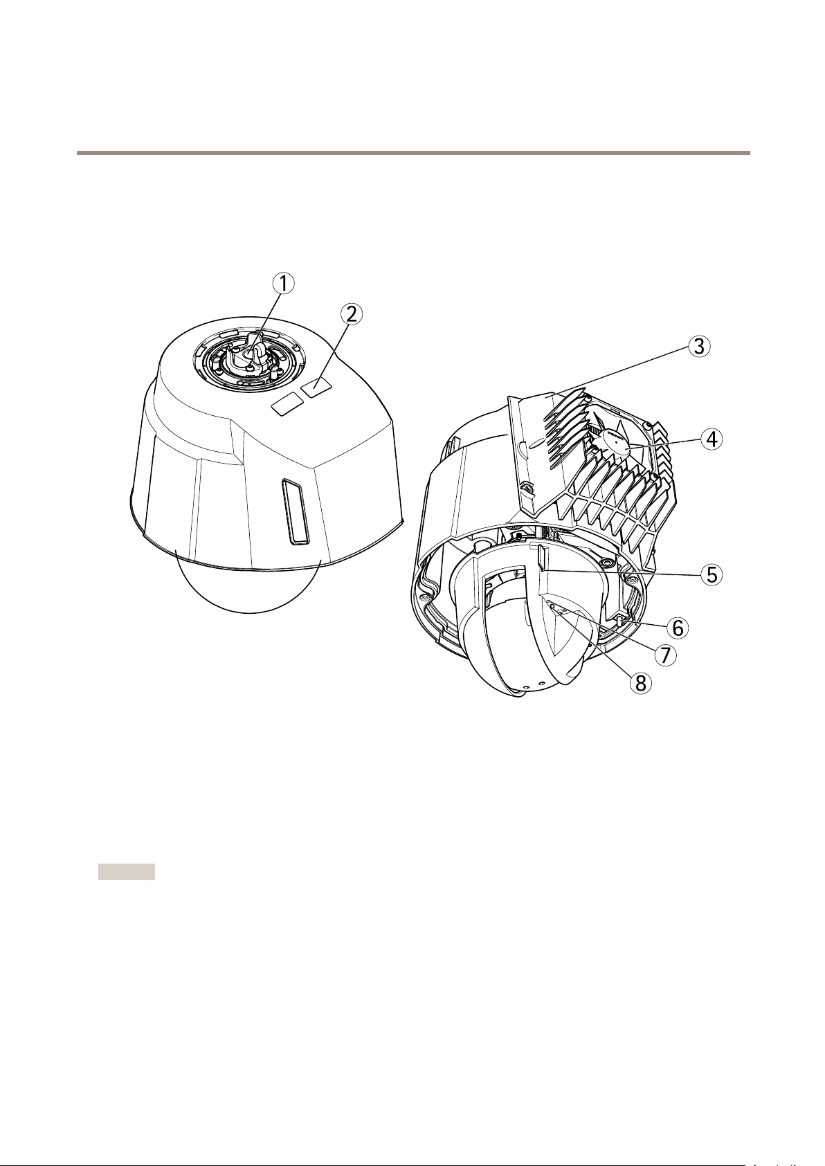
Camera
1
Network connector (High PoE)
2
Part number (P/N) & Serial number (S/N)
3
Cooling system
4
Fan
5
SD card slot
6
Power button
7
Status LED indicator
8
Control button
Important
Dust and particle buildup could affect the performance of the cooling system. To maintain the performance level, the outer
heat sink in the camera’s cooling system may need occasional or regular cleaning. See the product’s Installation Guide for
information on how to access and clean the outer heat sink.
Connectors and Buttons
For technical specications, see page 65.
6
Page 7

AXIS Q6045-C Mk II PTZ Dome Network Camera
Hardware Overview
Multi-connector
Terminal connector for connecting the supplied media converter switch, which provides the following signals:
• DC Power
• Network (Ethernet 10/100Base-T)
• Input/Output (I/O)
The supplied multi-connector cable is required in order to maintain the product’s NEMA/IP rating. For more information, see
Multi-Connector Cable on page 59.
SD Card Slot
An SD card (not included) can be used for local recording with removable storage. For more information, see Technical Specications.
TICE
NONONOTICETICE
To prevent corruption of recordings, the SD card should be unmounted before removal. To unmount, go to Setup > System
Options > Storage > SD Card and click Unmount.
Note
For SD card recommendations see www.axis.com
Control Button
For location of the control button, see Hardware Overview on page 6 .
The control button is used for:
• Resetting the product to factory default settings. See page 58.
• Connecting to an AXIS Video Hosting System service. See page 51. To connect, press and hold the button for about 3
seconds until the Status LED ashes green.
• Connecting to AXIS Internet Dynamic DNS Service. See page 51. To connect, press and hold the button for about 3 seconds.
Power Button
Press and hold the power button to temporarily power the product when the dome cover is removed. The power button is also used
with the control button to reset the camera to factory default settings. See page 58.
LED Indicators
LED
Status
Color
Unlit
Amber
Amber/red Flashes amber/red if network connection is unavailable or lost.
Red Flashes red for rmware upgrade failure.
Green Shows steady green for 10 seconds for normal operation after startup
Indication
Connection and normal operation
Steady during startup. Flashes during rmware upgrade.
completed.
7
Page 8
AXIS Q6045-C Mk II PTZ Dome Network Camera
Hardware Overview
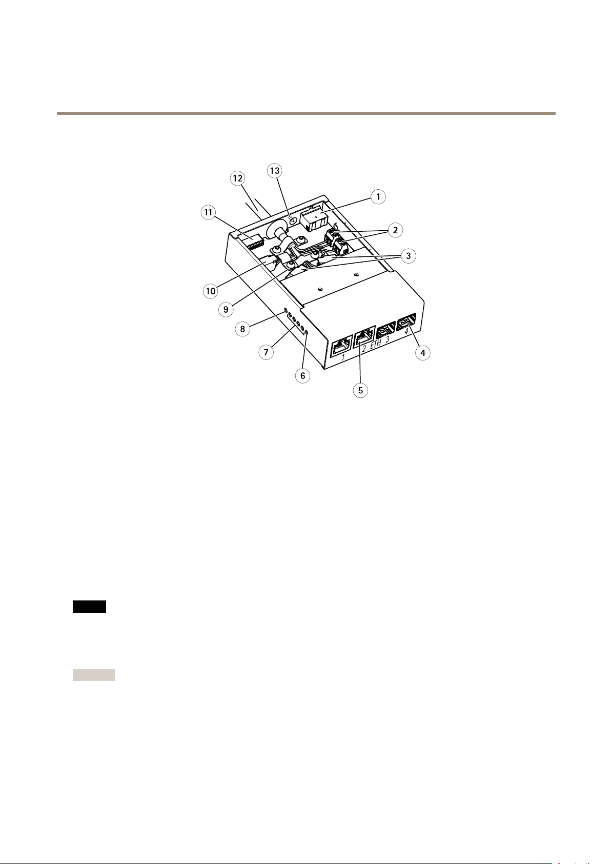
Media Converter Switch
1
Power connector (DC input)
2
Power connector (DC output)
3
Network connector (internal)
4
Network slot SFP (external) (2x)
5
Network connector RJ45 (external) (2x)
6
Camera LED indicator
7
Network LED indicator (4x)
8
Power LED indicator
9
Ground clip
10
I/O connector (internal)
11
I/O connector (external)
12
Multi-connector cable
13
Ground screw
Media Converter Switch Connectors
For technical specications, see page 65.
TICE
NONONOTICETICE
The product shall be connected using a shielded network cable (STP) or an optical ber cable. All cables connecting the
product to the network shall be intended for their specic use. Make sure that the network devices are installed in
accordance with the manufacturer’s instructions. For information about regulatory requirements, see Electromagnetic
Compatibility (EMC) on page 2 .
Important
The media converter switch does not support hotswapping. Disconnect power from the switch before swapping cameras. An
attempt to hotswap could cause the switch to freeze, in which case it must be restarted.
Power connector (DC input) - 2-pin terminal block for power input.
Power connector (DC output) - Two 2-pin terminal block for power output (pin 4 is not used).
Network connector RJ45 (external) - Two RJ45 connectors (10/100Base-T) for network connectivity.
8
Page 9

AXIS Q6045-C Mk II PTZ Dome Network Camera
Hardware Overview
Network slot SFP (external) - Two SFP slots (100Base-FX/1000Base-X) for network connectivity.
Each RJ45 and SFP port has its own dip switch. The dip switches control how the port forwards data. See Network Connector
Dip Switches.
Dip switch position Description of use
Default (middle)
Left A When connecting to a camera or a device that is not intended for viewing
Right
Network connector (internal) - Two 2-pin Ethernet terminal blocks.
I/O connector (external) - 6-pin congurable I/O terminal block, which is connected to the camera through the multi-connector
cable. Use with external devices in combination with, for example, tampering alarms, motion detection, event triggering, time lapse
recording and alarm notications. In addition to the 0 V DC reference point and power (DC output), the I/O connector provides the
interface to:
• Digital output – For connecting external devices such as relays and LEDs. Connected devices can be activated
by the VAPIX® Application Programming Interface, output buttons on the Live View page or by an Action Rule.
The output will show as active (shown under System Options > Port & Devices > Port Status) if the alarm
device is activated.
B When connecting to the network, directly or through a router or network
C
switch.
data.
When connecting to another media converter switch.
• Digital input – An alarm input for connecting devices that can toggle between an open and closed circuit, for
example: PIRs, door/window contacts, glass break detectors, etc. When a signal is received the state changes and
the input becomes active (shown under System Options > Port & Devices > Port Status).
I/O connector (internal) - 2–pin I/O terminal block.
Network Connector Dip Switches
Important
Always use the default dip switch setting (position B) if the relationship between devices in the system is not dened.
The camera attaches a particular VLAN tag to all its forwarded multicast packages. The media converter switch manages how these
multicast packages are forwarded between cameras, media converter switches and other network devices. This especially useful when
connecting the camera and media converter switch to the network in a daisy chain.
By changing the position of the dip switches, each network connector port in the media converter switch can be congured
to manage multicasts in three different ways.
9
Page 10

AXIS Q6045-C Mk II PTZ Dome Network Camera
Hardware Overview
Dip switch position Description
Default (middle)
Left A Block multicast packages that have a VLAN tag. Use this setting when connecting to a device that is
Right
VLAN tags are used to create independent logical networks, virtual local area networks (VLANs), within a physical network. Multiple
media converter switches that are connected to each other in a daisy chain are members of the same VLAN. The media converter
switches tag the multicast packages moving between them so that the next media converter switch in line knows the destination of
the packages. In other words, the VLAN tag serves as a VLAN identier. VLAN tagging should only be used when using multiple
cameras and media converter switches because forwarding multicast packages with a VLAN tag only serves a purpose when the port
is connected to another media converter switch, which might be connected to potential viewers.
Note
When connecting an outgoing media converter switch network connector to another type of network device, set the dip
switch to position A to protect the device from multicast trafc.
B Remove VLAN tags from forwarded multicast packages. Use this setting when connecting to the
network, directly or through a router or network switch.
not intended for multicast viewing.
Forward multicast packages with a VLAN tag. Use this setting when connecting to another media
C
converter switch.
Media Converter Switch LED Indicators
LED
Power
Network (4x)
Camera Green
Color
Unlit
Green DC power connected.
Amber 10 Mbit connection. Flashes during activity.
Green
Indication
DC power unconnected or current protection engaged (power overload)
100/1000 Mbit connection. Flashes during activity.
100 Mbit connection. Flashes during activity.
10
Page 11

AXIS Q6045-C Mk II PTZ Dome Network Camera
Access the Product
Access the Product
To install the Axis product, refer to the Installation Guide supplied with the product.
The product can be used with most operating systems and browsers. The recommended browsers are Internet Explorer with Windows,
Safari with Macintosh and Firefox with other operating systems. See Technical Specications on page 65.
To view streaming video in Internet Explorer, allow installation of AXIS Media Control (AMC) when prompted.
The Axis product includes one (1) H.264 decoder license for viewing video streams. The license is automatically installed with AMC.
The administrator can disable the installation of the decoders, to prevent installation of unlicensed copies.
Note
• QuickTimeTMis also supported for viewing H.264 streams.
• If your computer restricts the use of additional software components, the product can be congured to use a Java applet
for viewing Motion JPEG.
Access from a Browser
1. Start a browser (Chrome, Internet Explorer, Firefox, Safari).
2. Enter the IP address or host name of the Axis product in the browser’s Location/Address eld. To access the product from a
Macintosh computer (Mac OS X), click on the Bonjour tab and select the product from the drop-down list.
If you do not know the IP address, use AXIS IP Utility to locate the product on the network. For information about how to
discover and assign an IP address, see the Installation and Management Software CD or the document Assign an IP Address
and Access the Video Stream on Axis Support web at www.axis.com/techsup
3. Enter your user name and password. If this is the rst time the product is accessed, the root password must rst be
congured. For instructions, see Set the Root Password on page 11 .
4. The product’s Live View page opens in your browser.
Note
The controls and layout of the Live View page may have been customized to meet specic installation requirements and
user preferences. Consequently, some of the examples and functions featured here may differ from those displayed in
your own Live View page.
Access from the Internet
Once connected, the Axis product is accessible on your local network (LAN). To access the product from the Internet you must
congure your network router to allow incoming data trafc to the product. To do this, enable the NAT-traversal feature, which
will attempt to automatically congure the router to allow access to the product. This is enabled from Setup > System Options >
Network > TCP/IP Advanced.
For more information, see NAT traversal (port mapping) for IPv4 on page 52. See also AXIS Internet Dynamic DNS Service at
www.axiscam.net
For Technical notes on this and other topics, visit the Axis Support web at www.axis.com/techsup
Set the Root Password
To access the Axis product, you must set the password for the default administrator user root. This is done in the Congure Root
Password dialog, which opens when the product is accessed for the rst time.
To prevent network eavesdropping, the root password can be set via an encrypted HTTPS connection, which requires an HTTPS
certicate. HTTPS (Hypertext Transfer Protocol over SSL) is a protocol used to encrypt trafc between web browsers and servers. The
HTTPS certicate ensures encrypted exchange of information. See HTTPS on page 47.
11
Page 12
AXIS Q6045-C Mk II PTZ Dome Network Camera
Access the Product
The default administrator user name root is permanent and cannot be deleted. If the password for root is lost, the product must be
reset to the factory default settings. See Reset to Factory Default Settings on page 58.
To set the password via a standard HTTP connection, enter it directly in the dialog.
To set the password via an encrypted HTTPS connection, follow these steps:
1. Click Use HTTPS.
A temporary certicate (valid for one year) is created, enabling encryption of all trafc to and from the product, and the
password can now be set securely.
2. Enter a password and then re-enter it to conrm the spelling.
3. Click OK. The password has now been congured.
The Live View Page
The controls and layout of the Live View page may have been customized to meet specic installation requirements and user
preferences. Consequently, some of the examples and functions featured here may differ from those displayed in your own Live View
page. The following provides an overview of each available control.
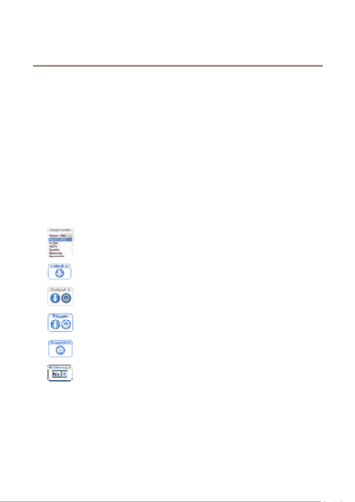
Controls on the Live View Page
Select a stream prole for the Live View page from the Stream Prole drop-down list. For information about how
to congure stream proles, see page 20.
Click Pulse to activate the product’s output port for a dened period of time. For information about how to
enable and congure output buttons, see page 26.
Click the Active/Inactive buttons to manually activate and inactive the product’s output port. For information
about how to enable and congure output buttons, see page 26.
The Manual Trigger button is used to trigger an action rule from the Live View page. For information about how to
congure and enable the button, see Manual Trigger on page 12.
Click Snapshot to save a snapshot of the video image. This button is primarily intended for use when the
AXIS Media Control viewer toolbar is not available. Enable this button from Live View Cong > Action Buttons.
Enable or disable the Gatekeeper by selecting On or Off from the drop-down list. For more information about the
Gatekeeper, see page 28.
Manual Trigger
The Manual Trigger is used to trigger an action rule from the Live View page. The manual trigger can for example be used to
validate actions during product installation and conguration.
To congure the manual trigger:
1. Go to Setup > Events.
2. Click Add to add a new action rule.
12
Page 13

AXIS Q6045-C Mk II PTZ Dome Network Camera
Access the Product
3. From the Trigger drop-down list, select Input Signal.
4. From the second drop-down list, select Manual Trigger.
5. Select the desired action and congure the other settings as required.
For more information about action rules, see Events on page 40.
To show the manual trigger buttons in the Live View page:
1. Go to Setup > Live View Cong.
2. Under Action Buttons, select Show manual trigger button.
AXIS Media Control viewer toolbar
The AXIS Media Control viewer toolbar is available in Internet Explorer only. See AXIS Media Control (AMC) on page 15 for more
information. The toolbar displays the following buttons:
The Play button connects to the Axis product and starts playing a media stream.
The Stop button stops the media stream.
The Snapshot button takes a snapshot of the video image. The location where the image is saved can be specied
in the AMC Control Panel.
Click the View Full Screen button and the video image will ll the entire screen. Press ESC (Escape) on the computer
keyboard to cancel full screen view.
The Record button is used to record the current video stream. The location where the recording is saved can be specied in
the AMC Control Panel. Enable this button from Live View Cong > Viewer Settings.
PTZ Controls
The Live View page also displays Pan/Tilt/Zoom (PTZ) controls. The administrator can enable/disable controls for specied users under
System Options > Security > Users.
With the PTZ Control Queue enabled the time each user is in control of the PTZ settings is limited. Click the buttons to request or
release control of the PTZ controls. The PTZ Control Queue is set up under PTZ > Control Queue.
Click the Emulate joystick mode button and click in the image to move the camera view in the direction of the
mouse pointer.
Click the Center mode button and click in the image to center the camera view on that position. The center mode
button could also be used to zoom in on a specic area. Click in the image and drag to draw a rectangle surrounding
the area to be magnied. To zoom out, rotate the mouse wheel.
Click the Ctrl panel button to open the PTZ control panel which provides additional PTZ controls.
User-dened buttons can also appear in the Control panel. See Controls on page 31.
Select a recorded tour and click to play a previously recorded tour and click to stop. See
Tour Recording on page 29.
Select a PTZ preset position to steer the camera view to the saved position. See Preset Positions
on page 27.
Click the Start Auto Track button to start autotracking directly from the Live View page. See
Autotracking on page 28.
13
Page 14
AXIS Q6045-C Mk II PTZ Dome Network Camera
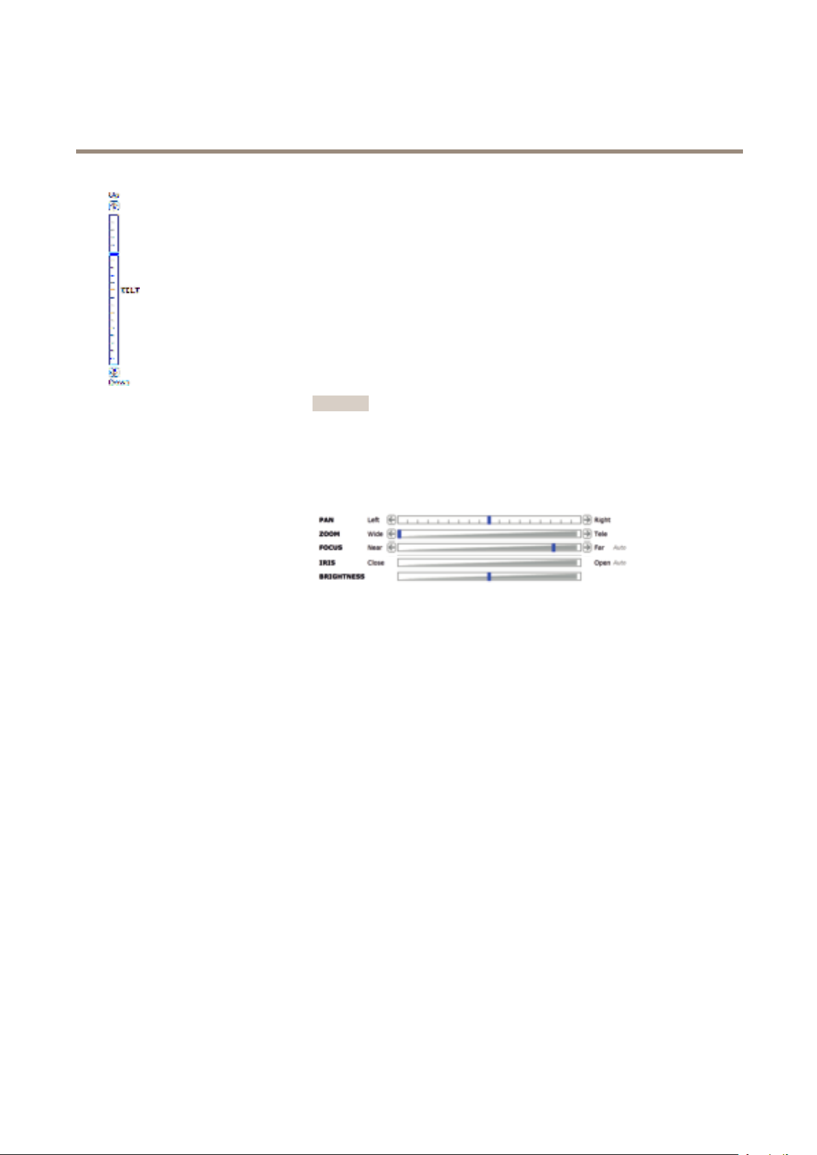
Access the Product
Pan and Tilt bars – Use the arrows to pan and tilt the camera view, or click on a
position on the bar to steer the camera view to that position.
Zoom bar – Use the arrows to zoom in and out, or click on a position on the bar to
zoom to that position.
Focus bar – Use the arrows to focus the camera, or click on a position on the bar
to set the focus position. Using the focus bar will disable the product’s autofocus.
To re-enable, use the PTZ control panel which is opened by clicking the Ctrl panel
button (see above).
Iris bar – Click on a position on the iris bar to change the degree to which the iris is
opened. This will disable the product’s auto iris. To re-enable, use the PTZ control panel
which is opened by clicking the Ctrl panel button (see above). If auto iris is enabled,
Auto is visible next to the Iris bar bar, see below.
Important
Adjusting the iris position will affect the shutter speed and gain. The default
setting is recommended.
Brightness bar – Click on a position on the brightness bar to adjust the image
brightness. This setting will not be saved. To make a saved change, go to Setup >
Video > Camera Settings > Brightness and adjust the brightness.
The PTZ controls can be disabled under PTZ > Advanced > Controls, see Controls on page 31.
14
Page 15

AXIS Q6045-C Mk II PTZ Dome Network Camera
Media Streams
Media Streams
The Axis product provides several video stream formats. Your requirements and the properties of your network will determine the
type you use.
The Live View page in the product provides access to H.264 and Motion JPEG video streams, and to the list of available stream
proles. Other applications and clients can access video streams directly, without going via the Live View page.
How to Stream H.264
H.264 can, without compromising image quality, reduce the size of a digital video le by more than 80% compared with the Motion
JPEG format and as much as 50% more than the MPEG-4 standard. This means that much less network bandwidth and storage space
are required for a video le. Or seen another way, much higher video quality can be achieved for a given bit rate.
Deciding which combination of protocols and methods to use depends on your viewing requirements, and on the properties of
your network. The available options in AXIS Media Control are:
Unicast RTP
RTP over RTSP
RTP over RTSP over HTTP
Multicast RTP
AXIS Media Control negotiates with the Axis product to determine the transport protocol to use. The order of priority, listed in the
AMC Control Panel, can be changed and the options disabled, to suit specic requirements.
Note
H.264 is licensed technology. The Axis product includes one H.264 viewing client license. Installing additional unlicensed
copies of the client is prohibited. To purchase additional licenses, contact your Axis reseller.
This unicast method (RTP over UDP) is used
for live unicast video, especially when it is
important to always have an up-to-date video
stream, even if some frames are dropped.
This unicast method (RTP tunneled over RTSP)
is useful as it is relatively simple to congure
rewalls to allow RTSP trafc.
This unicast method can be used to traverse
rewalls. Firewalls are commonly congured to
allow the HTTP protocol, thus allowing RTP to
be tunneled.
This method (RTP over UDP) should be used for live multicast video. The video stream is always
up-to-date, even if some frames are dropped.
Multicasting provides the most efcient usage of bandwidth when there are large numbers of
clients viewing simultaneously. A multicast cannot however, pass a network router unless the
router is congured to allow this. It is not possible to multicast over the Internet, for example.
Note also that all multicast viewers count as one unicast viewer in the maximum total of 20
simultaneous connections.
Unicasting is used for video-on-demand
transmission so that there is no video trafc
on the network until a client connects and
requests the stream.
Note that there are a maximum of 20
simultaneous unicast connections.
MJPEG
This format uses standard JPEG still images for the video stream. These images are then displayed and updated at a rate sufcient
to create a stream that shows constantly updated motion.
The Motion JPEG stream uses considerable amounts of bandwidth, but provides excellent image quality and access to every image
contained in the stream. The recommended method of accessing Motion JPEG live video from the Axis product is to use the AXIS
Media Control in Internet Explorer in Windows.
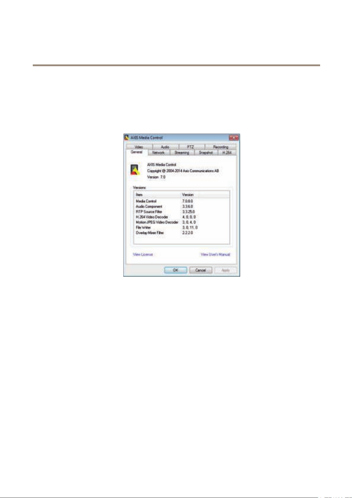
AXIS Media Control (AMC)
AXIS Media Control (AMC) in Internet Explorer in Windows is the recommended method of accessing live video from the Axis product.
15
Page 16
AXIS Q6045-C Mk II PTZ Dome Network Camera
Media Streams
The AMC Control Panel can be used to congure various video settings. Please see the AXIS Media Control User’s Manual for more
information.
The AMC Control Panel is automatically installed on rst use, after which it can be congured. Open the AMC Control Panel from:
• Windows Control Panel (from the Start screen or Start menu)
• Alternatively, right-click the video image in Internet Explorer and click Settings.
Alternative Methods of Accessing the Video Stream
You can also access video and images from the Axis product in the following ways:
• Motion JPEG server push (if supported by the client, Firefox, for example). This option maintains an open HTTP connection
to the browser and sends data as and when required, for as long as required.
• Still JPEG images in a browser. Enter the path http://<ip>/axis-cgi/jpg/image.cgi
• Windows Media Player. This requires AXIS Media Control and the H.264 decoder to be installed. The following paths
can be used:
- Unicast via RTP: axrtpu://<ip>/axis-media/media.amp
- Unicast via RTSP: axrtsp://<ip>/axis-media/media.amp
- Unicast via RTSP, tunneled via HTTP: axrtsphttp://<ip>/axis-media/media.amp
- Multicast: axrtpm://<ip>/axis-media/media.amp
• QuickTimeTM. The following paths can be used:
- rtsp://<ip>/axis-media/media.amp
- rtsp://<ip>/axis-media/media.3gp
16
Page 17

AXIS Q6045-C Mk II PTZ Dome Network Camera
Media Streams
Note
• <ip>= IP addess
• The Axis product supports QuickTime 6.5.1 and later.
• QuickTime may add latency to the video stream.
• It may be possible to use other players to view the H.264 stream using the paths above, although Axis does not guarantee
this.
17
Page 18

AXIS Q6045-C Mk II PTZ Dome Network Camera
Set Up the Product
Set Up the Product
The Axis product can be congured by users with administrator or operator rights. To open the product’s Setup pages, click Setup in
the top right-hand corner of the Live View page.
• Administrators have unrestricted access to all settings.
• Operators have access to all settings except System Options
See also the online help
.
Basic Setup
Basic Setup provides shortcuts to the settings that should be made before using the Axis product:
1. Users. See page 47.
2. TCP/IP. See page 49.
3. Date & Time. See page 49.
4. Video Stream. See page 19.
The Basic Setup menu can be disabled from System Options > Security > Users.
18
Page 19

AXIS Q6045-C Mk II PTZ Dome Network Camera
Video
Video
It is possible to congure the following video features in your Axis product:
• Video stream. See page 19.
• Stream proles. See page 20.
• Camera settings. See page 21.
• Overlay image. See page 22.
• Privacy mask. See page 24.
Video Stream
You can dene the following video stream settings from Video > Video Stream:
• Image. See page 19.
• H.264. See page 20.
• MJPEG. See page 20.
Pixel Counter
The pixel counter shows the number of pixels in an area of the image. The pixel counter is useful in situations where there is a
requirement that the image is a certain size, for example in face recognition.
The pixel counter can be accessed from:
• Video > Video Stream. Under Preview, click Open and select the Show pixel counter option to enable the rectangle
in the image. Use the mouse to move and resize the rectangle, or enter the number of pixels in the Width and Height
elds and click Apply.
• The Live View page in Internet Explorer with AXIS Media Control (AMC) in Windows. Right-click in the image and select
Pixel counter. Use the mouse to move and resize the rectangle.
Image
The default image settings can be congured under Video> Video Stream. Select the Image tab.
The following settings are available:
• Resolution. Select the default resolution.
• Compression. The compression level affects the image quality, bandwidth and le size of saved images; the lower the
compression, the higher the image quality with higher bandwidth requirements and larger le sizes.
• Rotate image. If required, the image can be rotated.
• Maximum frame rate. To avoid bandwidth problems, the frame rate allowed to each viewer can be Limited to a xed
amount. Alternatively, the frame rate can be set as Unlimited, which means the Axis product always delivers the highest
frame rate possible under the current conditions.
• Overlay settings. See Overlay on page 22.
Click Save to apply the new settings.
19
Page 20

AXIS Q6045-C Mk II PTZ Dome Network Camera
Video
H.264
H.264, also known as MPEG-4 Part 10/AVC, is a video compression standard that provides high quality video streams at low bit rates.
An H.264 video stream consists of different types of frames such as I-frames and P-frames. An I-frame is a complete image whereas
P-frames only contain the differences from previous frames.
The H.264 stream settings can be congured from the Video > Video Stream page. Select the H.264 tab. The settings dened in this
page will apply to all H.264 streams that do not use a stream prole.
The GOV length is the number of frames between two consecutive I-frames. Increasing the GOV length may save considerably on
bandwidth requirements in some cases, but may also have an adverse affect on image quality.
The Axis product supports the following H.264 prole(s):
• Baseline. The Baseline prole is recommended for clients that don’t support CABAC entropy coding.
• Main. The Main prole provides higher compression with maintained video quality compared to the Baseline prole but
requires more processing power to decode.
The bit rate can be set as Variable bit rate (VBR) or Constant bit rate (CBR). VBR adjusts the bit rate according to the image
complexity, using up more bandwidth for increased activity in the image, and less for lower image activity. When the activity in
the scene increases, the bit rate would usually increase as well. If there is a surplus in bandwidth, this may not be an issue and
selecting Variable bit rate (VBR) will be sufcient. But if bandwidth is limited, it is recommended to control the bit rate by selecting
Constant bit rate (CBR). When the activity in the scene increases, VBR adjusts the bit rate according to the complexity, using up
more bandwidth for increased activity in the scene, and less for lower scene activity. CBR allows you to set a target bit rate that
limits the bandwidth consumption.
The CBR target bit rate works like the ceiling of a tent. It limits the bit rate, while maintaining some exibility. The bit rate may bounce
up and down within the set target but when it nears the set target value, the limitation kicks in. However, because CBR will always
prioritize a continuous video stream, it allows temporary overshoots from the target bit rate. Because setting a target value prevents
the bit rate from increasing, frame rate and image quality are affected negatively. To partly compensate for this, select which variable
shall be prioritized, frame rate or image quality. Not setting a priority means that frame rate and image quality are equally affected.
The current bit rate can be set to appear as text overlay. Under Overlay Settings, select Include text and enter the modier
#b in the eld.
To apply the settings, click Save.
MJPEG
Sometimes the image size is large due to low light or complex scenery. Adjusting the maximum frame size helps to control the
bandwidth and storage used by the Motion JPEG video stream in these situations. Setting the frame size to the Default setting
provides consistently good image quality at the expense of increased bandwidth and storage usage in low light. Limiting the frame
size optimizes bandwidth and storage usage, but may give poor image quality. To prevent increased bandwidth and storage usage,
the maximum frame size should be set to an optimal value.
Stream Proles
A stream prole is a set of predened stream settings including resolution, compression, frame rate and overlay settings. Stream
proles can be used:
• When setting up recording using action rules. See Events on page 40.
• When setting up continuous recording. See Continuous Recording on page 45.
• In the Live View page – select the stream prole from the Stream prole drop-down list.
For quick setup, use one of the predened stream proles. Each predened prole has a descriptive name, indicating its purpose. If
required, the predened stream proles can be modied and new customized stream proles can be created.
To create a new prole or modify an existing prole, go to Setup > Video > Stream Proles.
To select a default stream prole for the Live View page, go to Setup > Live View Cong.
20
Page 21

AXIS Q6045-C Mk II PTZ Dome Network Camera
Video
Camera Settings
The Video > Camera Settings page provides access to advanced image settings for the Axis product.
Image Appearance
Increasing the Color level increases the color saturation. The value 100 gives maximum color saturation. The value 0 gives a
black and white image.
The image Brightness can be adjusted in the range 0–100, where a higher value produces a brighter image.
Increasing the Sharpness can increase bandwidth usage. A sharper image might increase image noise especially in low light
conditions. A lower setting reduces image noise, but the whole image will appear less sharp.
White Balance
White balance is used to make colors in the image appear the same regardless of the color temperature of the light source. The Axis
product can be set to automatically identify the light source and compensate for its color. Alternatively, select the type of light
source from the drop-down list. For a description of each available setting, see the online help
Wide Dynamic Range
.
Wide Dynamic Range (WDR) processing balances the brightest and darkest sections of a scene to produce an image that is balanced
in lighting to provide more detail. Wide dynamic range can improve the exposure when there is a considerable contrast between light
and dark areas in the image. There are three different WDR modes:
WDR 1 - contrast
WDR 2 - double exposure
WDR 3 - contrast and double exposure
The different WDR settings adjust for various amounts of contrast in the image. Use a higher WDR number for a higher contrast.
Enable WDR in intense backlight conditions. Disable WDR in low light conditions for optimal exposure.
Exposure Settings
Exposure control - These settings is used to adapt to the amount of light used. Automatic is the default setting and it can be
used in most situations. The shutter speed is automatically set to produce optimum image quality. Use Manual if you have special
requirements for the exposure setting and wish to lock it. Select the desired exposure time from the drop-down list.
Max exposure time - Select the maximum exposure time from the drop-down list. Increasing the exposure time will improve
image quality, but decrease the frame rate. There may also be an increase in motion blur. Checking Allow slow shutter decreases
the shutter speed in low light to improve image brightness.
Enable Backlight compensation - Select Enable Backlight compensation if a bright spot of light, for example a light bulb, causes
other areas in the image to appear too dark.
Highlight Compensation - The Axis product will detect a bright light from a source such as a torch or car headlights and mask that
image area. This setting is useful when the camera operates in a very dark area where a bright light may overexpose part of the image
and prevent the operator from seeing other parts of the scene.
Max gain - Measured in decibels (dB), gain describes the amount of amplication applied to a signal, in this case the visual
information in the image. A high level of amplication may provide a better image in very low light situations. A high gain will also
increase the amount of image noise.
Exposure zones - This settings determines which part of the image is used to calculate the exposure. For most situations, the Auto
setting can be used. For particular requirement, select a predened area.
IR cut lter - The IR cut lter prevents infrared (IR) light from reaching the image sensor. In poor lighting conditions, for example at
night, or when using an external IR lamp, set the IR cut lter to Off. This increases light sensitivity and allows the product to “see”
21
Page 22

AXIS Q6045-C Mk II PTZ Dome Network Camera
Video
infrared light. The image is shown in black and white when the IR cut lter is off. Set the IR cut lter to Auto to automatically
switch between On and Off according to the lighting conditions.
Day/Night shift priority - Use the Day/Night shift priority bar to determine when the camera shifts into either day mode or night
mode. By default, the camera will automatically change from day to night mode at a pre-dened level which corresponds to light
conditions. By dragging the bar handle towards the sun, the camera will change to day mode earlier and change to night mode late.
Image Settings
Important
The autofocus behavior is affected by factors such as light conditions, contrasts in the scene, and objects moving in and out. In
these conditions or scenes, a manual focus could be preferable to enhance performance and allow the camera to focus faster.
Autofocus enabled - Autofocus enables the camera to focus although the distance to different objects of interest is constantly
changing. Whenever the camera’s pan/tilt/zoom position is changed, the autofocus performs a search to nd the ideal focus point.
Automatic focusing is enabled by default. If the focus position is changed manually using the focus bar, autofocus will be disabled
even if enabled in Image Settings. In this case, use the PTZ control panel to enable autofocus, see PTZ Controls on page 13. If
required, the focus control can be disabled under PTZ > Advanced > Controls.
Auto defog - The product will detect fog and automatically lter it out to get a clear image. Select the level of fog removal from the
drop-down list. High implies that maximum fog removal is applied and off implies no fog removal. Auto defog can be activated
incorrectly in scenes with low contrast, high light level variations or when auto focus is slightly off. This can affect the image quality
by for example, increasing image contrast. Also, too much brightness can negatively impact the image quality when defog is active.
Noise reduction - Set to On to enable noise reduction. Noise reduction may increase the amount of motion blur.
Image freeze on PTZ - Select All movements to freeze the image while the camera is moving during a pan, tilt or zoom operation.
Once the camera reaches its new position, the view from that position is shown. Presets freezes the image only when the camera
moves between preset positions.
Overlay
Overlays are used to provide extra information, for example for forensic video analysis or during product installation and
conguration. Overlays are superimposed over the video stream.
An overlay text can display the current date and time, or a text string. When using a text string, modiers can be used to display
information such as the current bit rate or the current frame rate. For information about available modiers, see File Naming &
Date/Time Formats in the online help
It is also possible to display text when an action rule is triggered, see Use Overlay Text in an Action Rule.
To enable overlays:
1. Go to Video > Video Stream and select the Image tab.
2. To include an overlay image, select Include overlay image at the coordinates. The overlay image must rst be uploaded to
the Axis product, see Overlay Image.
3. To include date and time, select Include date and Include time.
4. To include a text string, select Include text and enter the text in the eld. Modiers can be used, see File Naming &
Date/Time Formats in the online help
.
.
5. Dene text overlay characteristics in the relevant elds.
6. Click Save.
To modify the date and time format, go to System Options > Date & Time. See Date & Time on page 49.
22
Page 23

AXIS Q6045-C Mk II PTZ Dome Network Camera
Video
Overlay Image
An overlay image is a static image superimposed over the video stream. The image, for example a company logo, is used to provide
extra information or to mask a part of the image.
Since it is static, the position and size of an overlay image will remain the same regardless of resolution and Pan/Tilt/Zoom
movements. Use a privacy mask to set up a dynamic mask which will always mask the specied part of monitored area.
For more information about privacy masks, see Privacy Mask on page 24.
To use an overlay image, the image must rst be uploaded to the Axis product. The uploaded image should be a Windows 24-bit BMP
image with maximum 250 colors. The image width and height, in pixels, must be exactly divisible by 4 and cannot be larger than the
maximum image resolution. If combining text and image overlays, take into consideration that the text overlay occupies 16 or 32
pixels in height (depending on the resolution) and has the same width as the video image.
To automatically scale the image to the resolution used by the Axis product, select the option Scale with resolution from the
Transparency Settings page which is displayed when uploading in the image.
To upload an overlay image:
1. Go to Video > Overlay Image.
2. Click Browse and browse to the le.
3. Click Upload.
4. The Transparency Settings page is now displayed:
- To make a color in the overlay image transparent, select Use transparency and enter the RGB hexadecimal value
for the color. Example: To make white transparent, enter #FFFFFF.
- To scale the image automatically, select Scale with resolution. The image will be scaled down to t the
resolution used by the Axis product.
5. Click Save.
To select the image to use as overlay:
1. Go to Video > Overlay Image.
2. Select the image to use from the Use overlay image list and click Save.
To display the overlay image:
1. Go to Video > Video Stream and select the Image tab.
2. Under Overlay Settings, select Include overlay image at the coordinates.
3. To control the image’s position, enter the X and Y coordinates. The X=0 and Y=0 position is the top left corner. If a part of
the image is positioned outside the video image, the overlay image will be moved so that the whole image is visible.
4. Click Save.
Use Overlay Text in an Action Rule
Action rules, see page 40, can display an overlay text when the rule is triggered. The text can be used to provide information for
forensic video analysis, notify surveillance operators or validate triggers and actions during product installation and conguration.
To display overlay text when an action rule is triggered, the modier #D should be used as described below. When the rule is
triggered, #D will be replaced by the text specied in the action rule.
Start by enabling overlay text in the video stream:
1. Go to Video > Video Stream and select the Image tab.
23
Page 24

AXIS Q6045-C Mk II PTZ Dome Network Camera
Video
2. Under Overlay Settings, select Include text.
3. Enter the modier #D and, optionally, additional text which will be displayed also when the action rule is not active.
Create the action rule:
1. Go to Events > Action Rules
2. Click Add to create a new rule.
3. Select a Trigger and, optionally, a Schedule and Additional conditions. See the online help for details.
4. From the Actions list, select Overlay Text
5. Enter the text to display in the Text eld. This is the text that #D will be replaced by.
6. Specify the Duration. The text can be displayed while the rule is active or for a xed number of seconds.
Example
To display the text “Motion detected” when motion is detected, enter #D in the Include text eld and enter “Motion detected” in
the Text eld when setting up the action rule.
Privacy Mask
A privacy mask is an area of solid color that prohibits users from viewing parts of the monitored area. Privacy masks cannot be
bypassed via the VAPIX® Application Programming Interface (API).
The Privacy Mask List, Video > Privacy Mask, shows all the masks that are currently congured in the Axis product and indicates
if they are enabled.
Since the Pan/Tilt/Zoom coordinates dene its size and position, a privacy mask is dynamic in relation to the monitored area. This
means that regardless of the angle and zoom of the lens, the same place or object will be hidden. To dene at what magnication the
mask should be displayed, zoom to the desired level and click Set level.
You can add a new mask, re-size the mask with the mouse, choose a color for the mask, and give the mask a name.
For more information, see the online help
Important
Adding many privacy masks may affect the product’s performance.
.
24
Page 25

AXIS Q6045-C Mk II PTZ Dome Network Camera
Configure the Live View Page
Configure the Live View Page
You can customize the Live View page and alter it to suit your requirements. It is possible to dene the following features of
the Live View page.
• Stream Prole. See page 20.
• Default Viewer for Browser. See page 25.
• Viewer Settings. See page 25.
• Action Buttons. These are the buttons described in Controls on the Live View Page on page 12.
• User Dened Links. See page 26.
• Output Buttons. See page 26.
Default Viewer for Browsers
From Live View Cong > Default Viewer select the default method for viewing video images in your browser. The product attempts
to show the video images in the selected video format and viewer. If this is not possible, the product overrides the settings and
selects the best available combination.
Browser Viewer Description
Windows Internet Explorer
Other browsers
For more information, please see the online help .
AMC
QuickTime
Java applet
Still image Displays still images only. Click the Refresh button in your browser to view a
Server Push
QuickTime
Java applet
Still image Displays still images only. Click the Refresh button in your browser to view a
Recommended viewer in Internet Explorer (H.264/Motion JPEG).
H.264.
A slower imaging alternative to AMC (Motion JPEG). Requires one of the
following installed on the client:
• JVM (J2SE) 1.4.2 or higher.
• JRE (J2SE) 5.0 or higher.
new image.
Recommended viewer for other browsers (Motion JPEG).
H.264.
A slower imaging alternative to Server Push (Motion JPEG only).
new image.
Viewer Settings
To congure options for the viewer, go to Live View Cong > Viewer Settings.
• Select Show viewer toolbar to display the AXIS Media Control (AMC) or the QuickTime viewer toolbar under the video
image in your browser.
• H.264 decoder installation. The administrator can disable installation of the H.264 decoder included with AXIS Media
Control. This is used to prevent installation of unlicensed copies. Further decoder licenses can be purchased from your
Axis reseller.
• Select Show crosshair in PTZ joystick mode to enable a cross that will indicate the center of the image in PTZ joystick
mode.
25
Page 26

AXIS Q6045-C Mk II PTZ Dome Network Camera
Configure the Live View Page
• Select Use PTZ joystick mode as default to enable joystick mode. The mode can be changed temporarily from the
PTZ control panel.
• Select Enable recording button to enable recording from the Live View page. This button is available when using the
AMC viewer. The recordings are saved to the location specied in the AMC Control Panel. See AXIS Media Control
(AMC) on page 15.
User Dened Links
To display user-dened links in the Live View page, select the Show custom link option, give the link a name and then enter the URL
to link to. When dening a web link do not remove the 'http://' from the URL address. Custom links can be used to run scripts or
activate external devices connected to the product, or they can link to a web page. Custom links dened as cgi links will run the
script in the background, in a hidden frame. Dening the link as a web link will open the link in a new window.
Output Buttons
External I/O devices connected to the Axis product’s output ports can be controlled directly from the Live View page.
Note
To enable this setting at least one I/O port must be congured as an output port. See I/O Ports on page 56.
To display output buttons in the Live View page:
1. Go to Setup > Live View Cong.
2. Under Output Buttons, select the type of control to use:
- Pulse activates the output for a dened period of time. The pulse time can be set from 1/100 second to 60
seconds.
- Active/Inactive displays two buttons, one or each action.
To congure the active and inactive states, go to System Options > Ports & Devices > I/O Ports and set the port’s Normal state.
For more information about I/O ports, see I/O Ports on page 56.
26
Page 27

AXIS Q6045-C Mk II PTZ Dome Network Camera
PTZ (Pan Tilt Zoom)
PTZ (Pan Tilt Zoom)
Preset Positions
A preset position is a saved view that can be used to quickly steer the camera to a specic position. A preset position consists of
the following values:
• Pan and tilt positions
• Zoom position
• Focus position (manual or automatic)
• Iris position (manual or automatic)
Access the Preset Positions
Preset positions can be accessed in several ways:
• By selecting the preset from the Preset positions drop-down list in the Live View Page.
• When setting up action rules. See page 40.
• When setting up guard tours. See page 29.
• When setting up the Gatekeeper. See page 28.
Add a Preset Position
1. Go to PTZ > Preset Positions.
2. Click in the image or use the controls to steer the camera view to the desired position, see Preset Positions.
3. Enter a descriptive name in the Current position eld.
4. If required, select Use current position as Home.
5. Click Add to save the preset position.
To include the preset position name in the overlay text, go to Video, select Include overlay text and enter the modier #P in the
eld. For more information about modiers, see File Naming & Date/Time Formats in the online help
.
Set the Home Position
The Home position is readily accessible by clicking the Home button on the Live View page and in the Preset Positions setup window.
To set a customized home position, select Use current position as Home when adding a preset position. The user-dened home
position will have (H) added, for example, Entrance (H). The default Home position, called “Home”, will still be available.
The product can be congured to return to the Home position when the PTZ functionality has been inactive for a specied length
of time. Enter the length of time in the Return to home when inactive eld and click Save. Set the time to zero to prevent the
product from automatically returning to the Home position.
Set New Pan 0°
Important
Set new Pan 0° affects all previously dened presets, guard tours, masks etc.
27
Page 28

AXIS Q6045-C Mk II PTZ Dome Network Camera
PTZ (Pan Tilt Zoom)
The product can be mounted in three different horizontal directions. This may cause the view from Pan 0° to be changed from the
original view. Click Set new Pan 0° to set the pan coordinate system to zero in the current direction. Set new Pan 0° can be useful
for instance when re-installing the product after maintenance.
Gatekeeper
The Active Gatekeeper monitors an area such as an entrance gate. When motion is detected in the monitored area, the Gatekeeper
will, depending on conguration, steer the camera to a selected preset position or start autotracking from a selected preset position.
Using a zoomed-in preset position can make it possible to, for example, read a license plate or identify a person. When motion
is no longer detected, the camera returns to its Home position after a dened time.
To enable the Gatekeeper, go to PTZ > Gatekeeper and follow the online instructions.
It is also possible to, for example, record video or save images (take a snapshot) while the Gatekeeper is active. Go to Events and set
up an action rule with PTZ Preset Reached or Autotracking as trigger.
Autotracking
The Axis product can detect movement in the eld of view, for example a moving vehicle or person. If autotracking is enabled, the
Axis product will automatically pan and tilt to follow the moving object. In case there is much simultaneous movement, the area with
the most movement will be followed. Autotracking continues until the moving object stops or disappears from the monitored area.
Movement in areas blocked by privacy masks and in exclude areas does not trigger autotracking.
It is strongly recommended to enable the PTZ Control Queue if autotracking and guard tour are enabled simultaneously. In the PTZ
Control Queue, guard tour has lower priority than autotracking, so autotracking will not be abandoned to start a guard tour.
Conguration
Start/Stop Autotracking - Click Start to enable autotracking. To disable autotracking, click Stop.
Settings - The Movement trigger sensitivity level can be set to Low, Medium or High. Medium is usually a good choice, depending on
the size of the moving objects and the image contrast, a low or high sensitivity might be more suitable.
Exclude Areas
Exclude areas are areas where movement is to be ignored.
Note
Movement in an area blocked by a privacy mask is always ignored.
1. Click Add area to create an exclude area
2. Resize and move the area (the blue rectangle) to the desired position.
3. Enter a descriptive name and click Save.
To remove an area, click the name of the area and click Remove. To enable or disable an area, click the name of the area and
click Enable/Disable.
Max Limits
The pan and tilt limits restrict the area where autotracking is allowed. The area beyond the set limits will be ignored. This may prove
useful, for example, to avoid tracking birds in the sky. Between the pan start and end limits, autotracking is allowed going clockwise.
The illustrations show the difference between setting a range from 135° to 45° (1) and a range from 45° to 135° (2).
1. Select Enable tilt limit and Enable pan limit respectively to enable the tilt and pan limits.
2. Enter the Tilt angle and Pan limit values, or click the links and move the blue horizontal and vertical bars in the preview
window until satised.
28
Page 29

AXIS Q6045-C Mk II PTZ Dome Network Camera
PTZ (Pan Tilt Zoom)
3. Click Save.
Top view
A Pan limit start
B Pan limit end
Guard Tour
A guard tour displays the video stream from different preset positions, one-by-one, in a predetermined order or at random and for
congurable time periods. The enabled guard tour will keep running after the user has logged off or closed the browser.
The guard tour capability in this Axis product also includes tour recording. Tour recording is described in Tour Recording on page 29.
To add a guard tour:
1. Go to PTZ > Guard Tour and click Add.
2. Select Create a preset tour and click OK.
3. Enter a descriptive name.
4. Specify the pause length between runs.
5. Select an available preset position and click Apply.
6. Specify the Move Speed.
7. Specify the View Time in seconds or minutes.
8. Specify the View Order or select the Random view order option.
9. Click Save.
To modify or remove guard tours, go to PTZ > Guard Tour, select the guard tour in the Guard Tour List and click Modify/Remove.
For more information see the online help
.
Tour Recording
The guard tour function in this product includes tour recording, which allows recording of a custom tour using an input device such
as a joystick, mouse, keyboard or through the VAPIX® Application Programming Interface (API). A recorded tour displays the video
stream of the recorded sequence of Pan/Tilt/Zoom movements, including their variable speeds and lengths.
29
Page 30

AXIS Q6045-C Mk II PTZ Dome Network Camera
PTZ (Pan Tilt Zoom)
To add a recorded tour:
1. Go to PTZ > Guard Tour and click Add.
2. Select Create a record tour and click OK.
3. Enter a descriptive name.
4. Specify the pause length between runs.
5. Click
6. When satised, click
7. Click OK.
Note
Only the name of the recorded tour and pause between runs can be modied. Starting a new recording will overwrite the
existing guard tour.
The recorded tour can be activated from the Live View and Guard Tour pages or through events. For more information see the
online help
to start recording the Pan/Tilt/Zoom movements.
.
.
OSDI Zones
On-Screen Direction Indicator (OSDI) zones can be included in the overlay text (see Overlay on page 22) to aid the user to navigate
the Axis product. Each OSDI zone is set up with coordinates and a descriptive name.
OSDI zones are set up under PTZ > OSDI Zones. The Axis product uses the coordinates of the center of the view to set the lower
left and upper right zone areas. First navigate to where you would like the lowermost left point of the OSDI zone to be located.
Click Get to set the coordinates. Proceed to where the upper right point of zone should be located and click Get. Give the zone a
descriptive name and click OK.
To include the name of the OSDI zone in the overlay text, go to Video < Video Stream < Overlay Settings. Check the Include
text box and enter the modier #L in the eld. For more information about modiers, see File Naming & Date/Time Formats in
the online help
.
Advanced
Limits
Dene the pan, tilt, zoom and focus limits for the Axis product. Movements to the left and right, up and down, can be restricted to
narrow the area under surveillance.
When Enable E-ip is selected, as it tilts down and continues to pan backwards, the Axis product will automatically correct the view
and ip it 180 degrees. The left limit must be set to –180 degrees and the right limit to 180 degrees for e-ip to work.
Near focus limit is used to prevent the camera from autofocusing on objects close to the camera. This way, the camera can ignore
objects such as overhead wires, streetlights, or other cameras placed close to the camera.
To make the camera focus on the areas of interest, set the near focus limit to a value that is greater than the distance at which the
uninteresting objects tend to appear. See illustration below where x is the near focus limit value.
30
Page 31

AXIS Q6045-C Mk II PTZ Dome Network Camera
PTZ (Pan Tilt Zoom)
Move speed sets the speed of the camera’s pan and tilt movements. The default setting is maximum speed.
When using a joystick (or emulating one with the mouse) the Enable proportional speed setting can be used to reduce the maximum
pan/tilt movement speed, i.e. the speed the camera view moves at when the joystick is pushed all the way out in any direction. This is
useful then the view is zoomed in on an object.
See the online help
for more information.
Controls
Advanced PTZ settings can be congured under PTZ > Advanced > Controls.
The Panel Shortcut Command Buttons list shows the user-dened buttons that can be accessed from the Live View page’s Ctrl
panel. These buttons can be used to provide direct access to commands issued using the VAPIX® application programming interface.
Click Add to add a new shortcut command button.
The following PTZ controls are enabled by default:
• Pan control
• Tilt control
• Zoom control
• Focus control
• Iris control
To disable specic controls, deselect the options under Enable/Disable controls.
Note
Disabling PTZ controls will not affect preset positions. For example, if the tilt control is disabled, the product can still move to
preset positions that require a tilt movement.
31
Page 32

AXIS Q6045-C Mk II PTZ Dome Network Camera
PTZ (Pan Tilt Zoom)
Control Queue
The administrator can set up a queue for PTZ controllers from PTZ > Control Queue. Once set up, the PTZ Control Queue buttons
appear in the Live View page offering one viewer exclusive control for a limited period of time. Other users will be placed in queue.
A user who belongs to a group (see Users on page 47) with a higher PTZ priority can go before other users in the queue and take
control of the product. The order of priority is as follows:
1. Administrator — An administrator takes over PTZ control regardless of who is rst in queue. The administrator will be
removed from the queue 60 seconds after the last PTZ control command.
2. Event — The Axis product can be congured to go to a preset position when triggered by an alarm (see Events on page 40).
The event will immediately be placed rst in the queue except when an administrator is in control.
3. Operator — Same as administrator but with lower priority
4. Guard Tour — A guard tour (see page 29) has PTZ control for an indenite period of time. It may be overridden by an
operator, event or administrator. The guard tour will resume when higher priority groups leave the queue.
5. Viewer — Multiple viewers must wait for their turn. The viewer has 60 seconds PTZ control before control is passed
on to the next viewer in queue.
Note
• The administrator can enable and disable PTZ controls for selected users.
• To identify different users in the viewer group, cookies must be enabled on the client.
32
Page 33

AXIS Q6045-C Mk II PTZ Dome Network Camera
Detectors
Detectors
Shock Detection
Enable Shock Detection from the Detectors menu. Shock detection is used, for example, to generate an alarm if the product is hit
by an object.
Use the Shock sensitivity slider to adjust the sensitivity level at which the product should send an alarm upon being hit. Low
sensitivity value implies that the product will generate an alarm only if the hit is powerful.
Motion Detection
Motion detection is used to generate an alarm whenever movement starts or stops in the camera view.
Motion detection is congured by dening up to 10 Include and Exclude windows:
• Include windows — dene areas where motion should be detected
• Exclude windows — dene areas within an Include window that should be ignored (areas outside Include windows
are automatically ignored).
For instructions, see Set Up Motion Detection Windows on page 33.
To control the number of motion detection alarms, the parameters Object Size, History and Sensitivity can be adjusted. See
Motion Detection Parameters on page 33.
Once motion detection windows are congured, the Axis product can be congured to perform actions when motion is detected.
Possible actions include uploading images and start recording. For more information, see Set Up Action Rules on page 40.
Note
• Using the motion detection feature may decrease the product’s overall performance.
• The position of the Motion Detection Window is relative to the orientation of the Camera. Changing the orientation of the
camera will also change the position of the Motion Detection Window.
Set Up Motion Detection Windows
To set up a motion detection Include Window, follow these instructions:
1. Go to Detectors > Motion Detection.
2. Select the Congure Included Windows option and click New. Select the new window in the list of windows and
enter a descriptive name.
3. Adjust the size (drag the bottom right-hand corner) and the position (click on the text at the top and drag to the desired
position) of the window.
4. Adjust the Object Size, History and Sensitivity prole sliders (see Motion Detection Parameters for details). Any detected
motion within an active window is indicated by red peaks in the Activity window.
5. Click Save.
To exclude parts of the include window, select the Congure Excluded Windows and position the exclude window within the
include window.
To delete an include or exclude window, select the window in the list of windows and click Del.
Motion Detection Parameters
The parameters controlling motion detection are described in the table below:
33
Page 34

AXIS Q6045-C Mk II PTZ Dome Network Camera
Detectors
Parameter
Description
High level (100%)
Medium level (50%)
Low level (0%)
Recommended values
Default values
Note
• To trigger on small objects or movements, use several small motion detection windows rather than one large window
and select a low object size.
• To avoid triggering on small objects, select a high object size.
• While monitoring an area where moving objects are not expected, select a high history level. This will cause motion
detection to trigger as long as the object is present in the window.
• To only detect ashing light, select a low sensitivity. In other cases high sensitivity is recommended.
Object Size
Object size relative to window
size.
Only very large objects trigger
motion detection.
Even very small objects trigger
motion detection.
5–15% 60–90% 75–95%
15% 90% 90%
History
Object memory length.
An object that appears in
the window triggers motion
detection for a long time
before it is considered as
non-moving.
An object that appears in
the window triggers motion
detection only for a very short
time before it is considered as
non-moving.
Sensitivity
Difference in luminance
between background and
object.
Ordinary colored objects on
ordinary backgrounds trigger
motion detection.
A large difference in luminance
is required to trigger motion
detection.
Only very bright objects on
a dark background trigger
motion detection.
Basic Video Analytics
The Basic Video Analytics section include the following detectors:
• Object Removed, see page 34
• Enter/Exit Detector, see page 35
• Fence Detector, see page 36
• Object Counter, see page 36
Important
• To activate a detector, the saved preset must be selected in the drop-down list. The detector will only be enabled at the
preset, see Preset Positions on page 27. Note that the Area of interest and Object size are not visible in Preset Positions,
only under the Detectors menu. If the pan/tilt/zoom position is changed, the detector is disabled.
• The detector will not register an object if the speed of the object is too high, if the object is too close to the camera, if the
difference in luminance between the object and the background is insufcient, or if the camera is autofocusing.
Object Removed
Object Removed is used to trigger an alarm if a detected object within a pre-dened area of interest has disappeared. Do the
following to set the detector:
Note
Use the Drawing Opacity slidebar to dene how transparent the area of interest or object size shape should be. Note
that this change will not be saved.
34
Page 35

AXIS Q6045-C Mk II PTZ Dome Network Camera
Detectors
1. Choose Area of interest from the drop-down list. Set the virtual area to detect if an object has disappeared from this
area of interest.
Important
When conguring Object size the view shall be zoomed out to Wide position.
2. Choose Object size from the drop-down list. Set the size limits of the object that should be detected. The camera will
detect any object whose size falls in between the minimum (blue shape) and maximum (white shape) range.
3. Use the Sensitivity slidebar to dene how sensitive the detection should be. The lower sensitivity selected on the Sensitivity
bar, the greater difference in luminance is needed between the object and the background for the detector to be activated.
See the online help for more information.
Enter/Exit Detector
Enter/Exit Detector is used to trigger an alarm if an object within a pre-dened area of interest has entered or left the area.
Do the following to set the detector:
Note
Use the Drawing Opacity slidebar to dene how transparent the area of interest or object size shape should be. Note
that this change will not be saved.
1. Choose Area of interest in the drop-down list. Set the virtual area to detect moving if any objects are entering or
exiting the area of interest.
Important
When conguring Object size the view shall be zoomed out to Wide position.
2. Choose Object size in the drop-down list. Set the size limits of the object that should be detected. The camera will detect
any object whose size falls in between the minimum (blue shape) and maximum (white shape) range.
35
Page 36

AXIS Q6045-C Mk II PTZ Dome Network Camera
Detectors
3. Use the Sensitivity slidebar to dene how sensitive the detection should be. The lower sensitivity selected on the Sensitivity
bar, the greater difference in luminance is needed between the object and the background for the detector to be activated.
See the online help for more information.
Fence Detector
Fence Detector is used to trigger an alarm if an object crosses a virtual line. Do the following to set the detector:
Note
Use the Drawing Opacity slidebar to dene how transparent the area of interest or object size shape should be. Note
that this change will not be saved.
1. Choose Area of interest from the drop-down list. Set the virtual line to detect objects moving across it.
Important
When conguring Object size the view shall be zoomed out to Wide position.
2. Choose Object size from the drop-down list. Set the size limits of the object that should be detected. The camera will
detect any object whose size falls in between the minimum (blue shape) and maximum (white shape) range.
3. Use the Sensitivity slidebar to dene how sensitive the detection should be. The lower sensitivity selected on the Sensitivity
bar, the greater difference in luminance is needed between the object and the background for the detector to be activated.
See the online help for more information.
Object Counter
Object Counter is used to count objects that move across a virtual line. Do the following to set the detector:
Note
Use the Drawing Opacity slidebar to dene how transparent the area of interest or object size shape should be. Note
that this change will not be saved.
1. Choose Area of interest from the drop-down list and set the virtual line. Objects crossing this virtual line will be counted.
Important
When conguring Object size the view shall be zoomed out to Wide position.
36
Page 37

AXIS Q6045-C Mk II PTZ Dome Network Camera
Detectors
2. Choose Object size from the drop-down list. Set the size limits of the object that should be detected. The camera will
detect any object whose size falls in between the minimum (blue shape) and maximum (white shape) range.
3. Use the Sensitivity slidebar to dene how sensitive the detection should be. The lower sensitivity selected on the
Sensitivity bar, the greater difference in luminance is needed between the object and the background for the detector to
be activated.
See the online help for more information.
Observations
The Observations element appears when a preset is selected in the drop-down list.
Left to Right - The value shows the amount of objects detected moving from left to right or, if the virtual line is horizontal,
objects detected moving downwards.
Right to Left - The value shows the amount of objects detected moving from right to left or, if the virtual line is horizontal, objects
detected moving upwards.
Total - The value shows the total amount of objects crossing the virtual line in any direction.
Refresh - Click Refresh to get updated observation values. The values are not automatically updated.
Reset - Click Reset to reset the observation values.
37
Page 38

AXIS Q6045-C Mk II PTZ Dome Network Camera
Applications
Applications
Third party applications can be uploaded to and installed on the Axis product. Applications add functionality to the product, for
example video analytics and intelligent video capabilities such as recognition, tracking, detection and counting. For information
about available applications, downloads, trials and licenses, go to www.axis.com/applications
Note
• It is recommended to run one application at a time.
• Avoid running applications when the built-in motion detection is active.
Application Licenses
Some applications need a license to run. Licenses can be installed in two ways:
• Automatic installation — requires access to the Internet
• Manual installation — obtain the license key from the application vendor and upload the key to the Axis product
To request a license, the Axis product serial number (S/N) is required. The serial number can be found on the product label and under
System Options > Support > System Overview.
Install Application
To install and start an application:
1. Go to Setup > Applications.
2. Under Upload Application, click Browse. Locate the application le and click Upload Package.
3. Install the license (if applicable). For instructions, see the documentation provided by the application vendor.
4. Start the application. Go to page Applications, select the application in the list of installed applications and click Start.
5. Congure the application. For instructions, see the documentation provided by the application vendor.
Note
• Applications can be uploaded by product administrators.
• Applications and licenses can be installed on multiple products at the same time using AXIS Camera Management, version
3.10 and later.
To generate a log le for the application, go to Applications. Select the application and click Log.
Application Considerations
If an application is upgraded, application settings, including the license, will be removed. The license must be reinstalled and
the application recongured.
If the Axis product’s rmware is upgraded, installed applications and their settings will remain unchanged, although this is not
guaranteed by Axis Communications AB. Note that the application must be supported by the new rmware. For information about
rmware upgrades, see Upgrade the Firmware.
If the Axis product is restarted, running applications will restart automatically.
If the Axis product is restored, installed applications remain unchanged but must be restarted. To start the application, go to
Setup > Applications. Select the application in the list of installed applications and click Start. For information about restoring
the Axis product, see Maintenance.
38
Page 39

AXIS Q6045-C Mk II PTZ Dome Network Camera
Applications
If the Axis product is reset to factory default, installed applications and their settings are removed. For information about factory
default, see Reset to Factory Default Settings.
39
Page 40

AXIS Q6045-C Mk II PTZ Dome Network Camera
Events
Events
The Event pages allow you to congure the Axis product to perform actions when different events occur. For example, the product
can start a recording or send an email notication when motion is detected. The set of conditions that denes how and when
the action is triggered is called an action rule.
Set Up Action Rules
An action rule denes the conditions that must be met for the product to perform an action, for example record video or send an
email notication. If multiple conditions are dened, all of them must be met to trigger the action.
For more information about available triggers and actions, see Triggers on page 40 and Actions on page 42.
The following example describes how to set up an action rule to record video to a network share if there is movement in the
camera’s eld of view.
Set up motion detection and add a network share:
1. Go to Detectors > Motion Detection and congure a motion detection window. See page 33
2. Go to System Options > Storage and set up the network share. See page 56.
Set up the action rule:
1. Go to Events > Action Rules and click Add.
2. Select Enable rule and enter a descriptive name for the rule.
3. Select Detectors from the Trigger drop-down list.
4. Select Motion Detection from the drop-down list. Select the motion detection window to use.
5. Optionally, select a Schedule and Additional conditions. See below.
6. Under Actions, select Record Video from the Type drop-down list.
7. Select a Stream prole and congure the Duration settings as described below.
8. Select Network Share from the Storage drop-down list.
To use more than one trigger for the action rule, select Additional conditions and click Add to add additional triggers. When using
additional conditions, all conditions must be met to trigger the action.
To prevent an action from being triggered repeatedly, a Wait at least time can be set. Enter the time in hours, minutes and seconds,
during which the trigger should be ignored before the action rule can be activated again.
The recording Duration of some actions can be set to include time immediately before and after the event. Select Pre-trigger time
and/or Post-trigger time and enter the number of seconds. When While the rule is active is enabled and the action is triggered
again during the post-trigger time, the recording time will be extended with another post-trigger time period.
For more information, see the online help
.
Triggers
Available action rule triggers and conditions include:
• Applications – Use installed applications to trigger the rule. See Applications on page 38.
• Detectors
40
Page 41

AXIS Q6045-C Mk II PTZ Dome Network Camera
Events
- Live Stream Accessed – Trigger the rule when any stream is accessed and during edge storage playback.
This can for example be used to send notications.
- Motion Detection – Trigger the rule when motion is detected. See Motion Detection on page 33.
- Shock Detected – Trigger the rule when the Axis product detects it has been tilted or hit. See Shock Detection
on page 33.
- Enter/Exit – Trigger the rule when an object has entered or exited the area. See Enter/Exit Detector on page 35.
- Fence Detector – Trigger the rule when an object has crossed a virtual line. See Fence Detector on page 36
- Object Removed – Trigger the rule when an object has been removed from a scene. See Object Removed
on page 34.
• Hardware
- Network – Trigger the rule if network connection is lost or restored. This can for example be used to start
recording to the SD card.
- Temperature – Trigger the rule if the temperature falls outside or inside the operating range of the product. This
can for example be used to send maintenance notications.
• Input Signal
- Digital Input Port – Trigger the rule when an I/O port receives a signal from a connected device. See I/O
- Manual Trigger – Trigger the rule using the Manual Trigger button in the Live View page. See Controls on
- Virtual Inputs – can be used by a VMS (Video Management System) to trigger actions. Virtual inputs can, for
• PTZ
- Autotracking – Trigger the rule when autotracking starts or stops. See Autotracking on page 28.
- Error – Trigger the rule if the PTZ functionality is not working correctly. This can for example be used to
- Ready – Trigger the rule when the PTZ functionality is ready to be used. This can for example be used to steer
• Storage
- Disruption – Trigger the rule if storage problems are detected, for example if the storage device is unavailable,
- Recording – Triggers the rule when the Axis product records to the storage device. The recording status trigger
Ports on page 56.
the Live View Page on page 12. This can for example be used to validate actions during product installation
and conguration.
example, be connected to buttons in the VMS user interface.
send maintenance notications.
the camera to a specic preset position when the product is started.
removed, full, locked or if other read or write problems occur. This can for example be used to send maintenance
notications.
can be used to notify the operator, for example by ashing LED lights, if the product has started or stopped to
record to the storage device. Note that, this trigger can be used only for edge storage recording status.
• System
• Time
- System Ready – Trigger the rule when the product has been started and all services are running. This can for
example be used to send a notication when the product restarts.
- Recurrence – Trigger the rule periodically. See Set Up Recurrences on page 44. This can for example be used to
upload an image every 5 minutes.
41
Page 42

AXIS Q6045-C Mk II PTZ Dome Network Camera
Events
- Use Schedule – Trigger the rule according to the selected schedule. See Create Schedules on page 43.
Actions
Available actions include:
• Day/Night Vision Mode – Set day mode (IR cut lter on) or night mode (IR cut lter off).
• Output Port – Activate an I/O port to control an external device.
• Overlay Text – Display an overlay text. See Use Overlay Text in an Action Rule on page 23.
• PTZ Control
- Autotracking – Start autotracking. See Autotracking on page 28.
- Preset Position – Go to a preset position.
- Guard Tour – Start a guard tour. See Guard Tour on page 29.
• Record Video – Record video to a selected storage.
• Send Images – Send images to a recipient.
• Send Notications – Send a notication message to a recipient.
• Send Video Clip – Send a video clip to a recipient.
Add Recipients
The product can send media les and messages to notify users about events. Before the product can send media les or notication
messages, you must dene one ore more recipients. For information about available options, see Recipient Types on page 42.
To add a recipient:
1. Go to Events > Recipients and click Add.
2. Enter a descriptive name.
3. Select a recipient Type.
4. Enter the information needed for the recipient type.
5. Click Test to test the connection to the recipient.
6. Click OK.
Recipient Types
The following recipients are available:
Recipient Use with action Notes
Email
Send Images
Send Notication
An email recipient can contain multiple email addresses. For
more information about email recipients, see Set Up Email
Recipients on page 43
FTP
Send Video Clip
Send Images
Send Video Clip
42
Page 43

AXIS Q6045-C Mk II PTZ Dome Network Camera
Events
HTTP
HTTPS Send Images
Network Share Send Images
TCP Send Notication
Send Images
Send Notication
Send Video Clip
Send Notication
Send Video Clip
Send Video Clip
Encrypted le transfer using HyperText Transfer Protocol
Secure (HTTPS).
Specify login information for the HTTPS server and validate
the server’s certicate. If there is a proxy between the Axis
product and the HTTPS server, also specify the proxy settings.
A network share can also be used as a storage device for
recorded video. Go System Options > Storage to congure
a network share before setting up a continuous recording or
an action rule to record video. For more information about
storage devices, see Storage on page 54.
Set Up Email Recipients
Email recipients can be congured by selecting one of the listed email providers, or by specifying the SMTP server, port and
authentication used by, for example, a corporate email server.
Note
Some email providers have security lters that prevent users from receiving or viewing large amount of attachments, from
receiving scheduled emails and similar. Check the email provider’s security policy to avoid delivery problems and locked
email accounts.
To set up an email recipient using one of the listed providers:
1. Go to Events > Recipients and click Add.
2. Enter a Name and select Email from the Type list.
3. Enter the email addresses to send emails to in the To eld. Use commas to separate multiple addresses.
4. Select the email provider from the Provider list.
5. Enter the user ID and password for the email account.
6. Click Test to send a test email.
To set up an email recipient using for example a corporate email server, follow the instructions above but select User dened as
Provider. Enter the email address to appear as sender in the From eld. Select Advanced settings and specify the SMTP server
address, port and authentication method. Optionally, select Use encryption to send emails over an encrypted connection. The server
certicate can be validated using the certicates available in the Axis product. For information on how to upload certicates,
see Certicates on page 48.
Create Schedules
Schedules can be used as action rule triggers or as additional conditions, for example to record video if motion is detected outside
ofce hours. Use one of the predened schedules or create a new schedule as described below.
To create a new schedule:
1. Go to Events > Schedules and click Add.
2. Enter a descriptive name and the information needed for a daily, weekly, monthly or yearly schedule.
43
Page 44

AXIS Q6045-C Mk II PTZ Dome Network Camera
Events
3. Click OK.
To use the schedule in an action rule, select the schedule from the Schedule drop-down list in the Action Rule Setup page.
Set Up Recurrences
Recurrences are used to trigger action rules repeatedly, for example every 5 minutes or every hour.
To set up a recurrence:
1. Go to Events > Recurrences and click Add.
2. Enter a descriptive name and recurrence pattern.
3. Click OK.
To use the recurrence in an action rule, rst select Time from the Trigger drop-down list in the Action Rule Setup page and then
select the recurrence from the second drop-down list.
To modify or remove recurrences, select the recurrence in the Recurrences List and click Modify or Remove.
44
Page 45

AXIS Q6045-C Mk II PTZ Dome Network Camera
Recordings
Recordings
The Axis product can be congured to record video continuously or according to an action rule:
• To start a continuous recording, see page 45.
• To set up action rules, see page 40.
• To access recordings, see Recording List on page 45.
• To congure camera controlled storage, see Storage on page 54.
Recording List
Recorded videos are listed on the Recordings > List page. The list shows each recording’s start date and time, duration and the
event that triggered the recording.
To play or download a recording, follow these steps:
1. Go to Recordings > List.
2. Use the lter to narrow the list of recordings. Enter the desired lter criteria and click Filter. Some lters may take
a long time to complete.
3. Select the recording.
4. Click Play to play the recording, or click Download to download the recording.
Multiple recordings can be downloaded at the same time. Select the recordings and click Download. The downloaded le is a zip le
containing a minimum of three les, of which the Matroska (mkv) les are the actual recordings. The recordings are time-stamped
with the date and time they were downloaded (that is, not the date the recordings were made).
Note
To play recordings in Windows Media Player, AXIS Matroska File Splitter must be installed. AXIS Matroska File Splitter
can be downloaded from www.axis.com/techsup/software
For detailed recording and video information, select a recording and click Properties.
To remove a recording, select the recording and click Remove.
Continuous Recording
The Axis product can be congured to continuously save video to a storage device. For information about storage devices, see Storage
on page 54. To prevent the disk from becoming full, it is recommended to congure the disk to automatically remove old recordings.
If a new stream prole is selected while a recording is ongoing, the recording will be stopped and saved in the recording list and a
new recording with the new stream prole will start. All previous continuous recordings will remain in the recording list until they
are removed manually or through automatic removal of old recordings.
To start a continuous recording, follow these steps:
1. Go to Recordings > Continuous.
2. Select Enabled.
3. Select the type of storage device from the Storage list.
4. Select a Stream prole to use for continuous recordings.
5. Click Save to save and start the recording.
45
Page 46

AXIS Q6045-C Mk II PTZ Dome Network Camera
Languages
Languages
Multiple languages can be installed in the Axis product. All web pages including the online help will be displayed in the selected
language. To switch languages, go to Setup > Languages and rst upload the new language le. Browse and locate the le and click
the Upload Language button. Select the new language from the list and click Save.
Note
• Resetting the product to factory default settings will erase any uploaded language les and reset the product language to
English.
• Clicking the Restore button on the Maintenance page will not affect the language.
• A rmware upgrade will not affect the language used. However if you have uploaded a new language to the product and
later upgrade the rmware, it may happen that the translation no longer matches the product's web pages. In this case,
upload an updated language le.
• A language already installed in the product will be replaced when a current or a later version of the language le is uploaded.
46
Page 47

AXIS Q6045-C Mk II PTZ Dome Network Camera
System Options
System Options
Security
Users
User access control is enabled by default and can be congured under System Options > Security > Users. An administrator can
set up other users by giving them user names and passwords. It is also possible to allow anonymous viewer login, which means
that anybody may access the Live View page.
The user list displays authorized users and user groups (access levels):
Viewer - Access to the Live View page
Operator - Access to the Live View page and to all settings except System Options
Administrator - Unrestricted access to all settings; can add, modify and remove other users.
Under HTTP/RTSP Password Settings, select the type of password to allow. You may need to allow unencrypted passwords if there are
viewing clients that do not support encryption, or if you upgraded the rmware and existing clients support encryption but need
to log in again and be congured to use this functionality.
Under User Settings, select the Enable anonymous viewer login option to allow anonymous users access to the Live View page.
Select the Enable anonymous PTZ control login to allow anonymous users access to the PTZ controls.
Deselect the Enable Basic Setup option to hide the Basic Setup menu. Basic Setup provides quick access to settings that should be
made before using the Axis product.
ONVIF
ONVIF (Open Network Video Interface Forum) is a global interface standard that makes it easier for end users, integrators, consultants,
and manufacturers to take advantage of the possibilities offered by network video technology. ONVIF enables interoperablity between
different vendor products, increased exibility, reduced cost and future-proof systems.
By creating a user you automatically enable ONVIF communication. Use the user name and password with all ONVIF communication
with the product. For more information see www.onvif.org
IP Address Filter
IP address ltering is enabled on the System Options > Security > IP Address Filter page. Once enabled, the listed IP address are
allowed or denied access to the Axis product. Select Allow or Deny from the list and click Apply to enable IP address ltering.
The administrator can add up to 256 IP address entries to the list (a single entry can contain multiple IP addresses).
HTTPS
HTTPS (HyperText Transfer Protocol over Secure Socket Layer, or HTTP over SSL) is a web protocol providing encrypted browsing.
HTTPS can also be used by users and clients to verify that the correct device is being accessed. The security level provided by
HTTPS is considered adequate for most commercial exchanges.
The Axis product can be congured to require HTTPS when users from different user groups (administrator, operator, viewer) log in.
To use HTTPS, an HTTPS certicate must rst be installed. Go to System Options > Security > Certicates to install and manage
certicates. See Certicates on page 48.
To enable HTTPS on the Axis product:
1. Go to System Options > Security > HTTPS
47
Page 48

AXIS Q6045-C Mk II PTZ Dome Network Camera
System Options
2. Select an HTTPS certicate from the list of installed certicates.
3. Optionally, click Ciphers and select the encryption algorithms to use for SSL.
4. Set the HTTPS Connection Policy for the different user groups.
5. Click Save to enable the settings.
To access the Axis product via the desired protocol, enter https:// or http:// in the address eld in a browser.
The HTTPS port can be changed on the System Options > Network > TCP/IP > Advanced page.
IEEE 802.1X
IEEE 802.1X is a standard for port-based Network Admission Control providing secure authentication of wired and wireless network
devices. IEEE 802.1X is based on EAP (Extensible Authentication Protocol).
To access a network protected by IEEE 802.1X, devices must be authenticated. The authentication is performed by an authentication
server, typically a RADIUS server, examples of which are FreeRADIUS and Microsoft Internet Authentication Service.
In Axis implementation, the Axis product and the authentication server identify themselves with digital certicates using EAP-TLS
(Extensible Authentication Protocol - Transport Layer Security). The certicates are provided by a Certication Authority (CA).
You need:
• a CA certicate to authenticate the authentication server.
• a CA-signed client certicate to authenticate the Axis product.
To create and install certicates, go to System Options > Security > Certicates. See Certicates on page 48. Many CA certicates
are preinstalled.
To allow the product to access a network protected by IEEE 802.1X:
1. Go to System Options > Security > IEEE 802.1X.
2. Select a CA Certicate and a Client Certicate from the lists of installed certicates.
3. Under Settings, select the EAPOL version and provide the EAP identity associated with the client certicate.
4. Check the box to enable IEEE 802.1X and click Save.
Note
For authentication to work properly, the date and time settings in the Axis product should be synchronized with an NTP
server. See Date & Time on page 49.
Certicates
Certicates are used to authenticate devices on a network. Typical applications include encrypted web browsing (HTTPS), network
protection via IEEE 802.1X and secure upload of images and notication messages for example via email. Two types of certicates
can be used with the Axis product:
Server/Client certicates - To authenticate the Axis product.
CA certicates - To authenticate peer certicates, for example the certicate of an authentication server in case the Axis product is
connected to an IEEE 802.1X protected network.
Note
Installed certicates, except preinstalled CA certicates, will be deleted if the product is reset to factory default. Preinstalled
CA certicates that have been deleted will be reinstalled.
A Server/Client certicate can be self-signed or issued by a Certicate Authority (CA). A self-signed certicate offers limited
protection and can be used before a CA-issued certicate has been obtained.
48
Page 49

AXIS Q6045-C Mk II PTZ Dome Network Camera
System Options
To install a self-signed certicate:
1. Go to Setup > System Options > Security > Certicates.
2. Click Create self-signed certicate and provide the requested information.
To create and install a CA-signed certicate:
1. Create a self-signed certicate as described above.
2. Go to Setup > System Options > Security > Certicates.
3. Click Create certicate signing request and provide the requested information.
4. Copy the PEM-formatted request and send to the CA of your choice.
5. When the signed certicate is returned, click Install certicate and upload the certicate.
Server/Client certicates can be installed as Certicate from signing request or as Certicate and private key. Select Certicate
and private key if the private key is to be upload as a separate le or if the certicate is in PKCS#12 format.
The Axis product is shipped with several preinstalled CA certicates. If required, additional CA certicates can be installed:
1. Go to Setup > System Options > Security > Certicates.
2. Click Install certicate and upload the certicate.
Date & Time
The Axis product’s date and time settings are congured under System Options > Date & Time.
Current Server Time displays the current date and time (24h clock). The time can be displayed in 12h clock in the text overlay (see
below).
To change the date and time settings, select the preferred Time mode under New Server Time:
• Synchronize with computer time – Sets date and time according to the computer’s clock. With this option, date and
time are set once and will not be updated automatically.
• Synchronize with NTP Server – Obtains date and time from an NTP server. With this option, date and time settings are
updated continuously. For information on NTP settings, see NTP Conguration on page 52.
If using a host name for the NTP server, a DNS server must be congured. See DNS Conguration on page 51.
• Set manually – Allows you to manually set date and time.
If using an NTP server, select your Time zone from the drop-down list. If required, check Automatically adjust for daylight saving
time changes.
The Date & Time Format Used in Images is the date and time format displayed as a text overlay in the video stream. Use the
predened formats or see File Naming & Date/Time Formats in the online help
time formats. To include date and time in the overlay text, go to Video and select Include date and Include time.
for information on how to create custom date and
Network
Basic TCP/IP Settings
The Axis product supports IP version 4 and IP version 6. Both versions can be enabled simultaneously, and at least one version
must always be enabled.
49
Page 50

AXIS Q6045-C Mk II PTZ Dome Network Camera
System Options
IPv4 Address Conguration
By default, the Axis product is set to use IPv4 (IP version 4) and to obtain the IP address automatically via DHCP. The IPv4 settings are
congured under System Options > Network > TCP/IP > Basic.
DHCP (Dynamic Host Conguration Protocol) allows network administrators to centrally manage and automate the assignment of
IP addresses. DHCP should only be enabled if using dynamic IP address notication, or if the DHCP can update a DNS server. It is
then possible to access the Axis product by name (host name).
If DHCP is enabled and the product cannot be accessed, run AXIS IP Utility to search the network for connected Axis products, or reset
the product to the factory default settings (see page 58) and then perform the installation again.
To use a static IP address, check Use the following IP address and specify the IP address, subnet mask and default router.
IPv6 Address Conguration
If IPv6 (IP version 6) is enabled, the Axis product will receive an IP address according to the conguration in the network router.
To enable IPv6, go to System Options > Network > TCP/IP > Basic. Other settings for IPv6 should be congured in the network router.
ARP/Ping
The product’s IP address can be assigned using ARP and Ping. For instructions, see Assign IP Address Using ARP/Ping on page 50.
The ARP/Ping service is enabled by default but is automatically disabled two minutes after the product is started, or as soon as an IP
address is assigned. To re-assign IP address using ARP/Ping, the product must be restarted to enable ARP/Ping for an additional
two minutes.
To disable the service, go to System Options > Network > TCP/IP > Basic and clear the option Enable ARP/Ping setting of IP address.
Pinging the product is still possible when the service is disabled.
Assign IP Address Using ARP/Ping
The product's IP address can be assigned using ARP/Ping. The command must be issued within 2 minutes of connecting power.
1. Acquire a free static IP address on the same network segment as the computer.
2. Locate the serial number (S/N) on the product label.
3. Open a command prompt and enter the following commands:
Linux/Unix syntax
arp -s <IP address> <serial number> temp
ping -s 408 <IP address>
Linux/Unix example
arp -s 192.168.0.125 00:40:8c:18:10:00 temp
ping -s 408 192.168.0.125
Windows syntax (this may require that you run the command prompt as an administrator)
arp -s <IP address> <serial number>
ping -l 408 -t <IP address>
Windows example (this may require that you run the command prompt as an administrator)
arp -s 192.168.0.125 00-40-8c-18-10-00
ping -l 408 -t 192.168.0.125
4. Check that the network cable is connected and then restart the product by disconnecting and reconnecting power.
50
Page 51

AXIS Q6045-C Mk II PTZ Dome Network Camera
System Options
5. Close the command prompt when the product responds with Reply from 192.168.0.125:... or similar.
6. Open a browser and type http://<IP address> in the Location/Address eld.
For other methods of assigning the IP address, see the Installation and Management Software CD or the document Assign an IP
Address and Access the Video Stream on Axis Support web at www.axis.com/techsup
Note
• To open a command prompt in Windows, open the Start menu and type cmd in the Run/Search eld.
• To use the ARP command in Windows 8/Windows 7/Windows Vista, right-click the command prompt icon and select
Run as administrator.
• To open a command prompt in Mac OS X, open the Terminal utility from Application > Utilities.
AXIS Video Hosting System (AVHS)
AVHS used in conjunction with an AVHS service, provides easy and secure Internet access to live and recorded video accessible from
any location. For more information and help to nd a local AVHS Service Provider go to www.axis.com/hosting
The AVHS settings are congured under System Options > Network > TCP IP > Basic. The possibility to connect to an AVHS service
is enabled by default. To disable, clear the Enable AVHS box.
One-click enabled - Press and hold the product’s control button (see Hardware Overview on page 6 ) for about 3 seconds to
connect to an AVHS service over the Internet. Once registered, Always will be enabled and the Axis product stays connected to
the AVHS service. If the product is not registered within 24 hours from when the button is pressed, the product will disconnect
from the AVHS service.
Always - The Axis product will constantly attempt to connect to the AVHS service over the Internet. Once registered the product will
stay connected to the service. This option can be used when the product is already installed and it is not convenient to use the
one-click installation.
AXIS Internet Dynamic DNS Service
AXIS Internet Dynamic DNS Service assigns a host name for easy access to the product. For more information, see www.axiscam.net
To register the Axis product with AXIS Internet Dynamic DNS Service, go to System Options > Network > TCP/IP > Basic. Under
Services, click the AXIS Internet Dynamic DNS Service Settings button (requires access to the Internet). The domain name currently
registered at AXIS Internet Dynamic DNS service for the product can at any time be removed.
Note
AXIS Internet Dynamic DNS Service requires IPv4.
Advanced TCP/IP Settings
DNS Conguration
DNS (Domain Name Service) provides the translation of host names to IP addresses. The DNS settings are congured under System
Options > Network > TCP/IP > Advanced.
Select Obtain DNS server address via DHCP to use the DNS settings provided by the DHCP server.
To make manual settings, select Use the following DNS server address and specify the following:
Domain name - Enter the domain(s) to search for the host name used by the Axis product. Multiple domains can be separated by
semicolons. The host name is always the rst part of a fully qualied domain name, for example, myserver is the host name in the
fully qualied domain name myserver.mycompany.com where mycompany.com is the domain name.
Primary/Secondary DNS server - Enter the IP addresses of the primary and secondary DNS servers. The secondary DNS server is
optional and will be used if the primary is unavailable.
51
Page 52

AXIS Q6045-C Mk II PTZ Dome Network Camera
System Options
NTP Conguration
NTP (Network Time Protocol) is used to synchronize the clock times of devices in a network. The NTP settings are congured under
System Options > Network > TCP/IP > Advanced.
Select Obtain NTP server address via DHCP to use the NTP settings provided by the DHCP server.
To make manual settings, select Use the following NTP server address and enter the host name or IP address of the NTP server.
Host Name Conguration
The Axis product can be accessed using a host name instead of an IP address. The host name is usually the same as the assigned DNS
name. The host name is congured under System Options > Network > TCP/IP > Advanced.
Select Obtain host name via IPv4 DHCP to use host name provided by the DHCP server running on IPv4.
Select Use the host name to set the host name manually.
Select Enable dynamic DNS updates to dynamically update local DNS servers whenever the Axis product’s IP address changes.
For more information, see the online help
Link-Local IPv4 Address
Link-Local Address is enabled by default and assigns the Axis product an additional IP address which can be used to access
the product from other hosts on the same segment on the local network. The product can have a Link-Local IP and a static
or DHCP-supplied IP address at the same time.
.
This function can be disabled under System Options > Network > TCP/IP > Advanced.
HTTP
The HTTP port used by the Axis product can be changed under System Options > Network > TCP/IP > Advanced. In addition to the
default setting, which is 80, any port in the range 1024–65535 can be used.
HTTPS
The HTTPS port used by the Axis product can be changed under System Options > Network > TCP/IP > Advanced. In addition to
the default setting, which is 443, any port in the range 1024–65535 can be used.
To enable HTTPS, go to System Options > Security > HTTPS. For more information, see HTTPS on page 47.
NAT traversal (port mapping) for IPv4
A network router allows devices on a private network (LAN) to share a single connection to the Internet. This is done by forwarding
network trafc from the private network to the “outside”, that is, the Internet. Security on the private network (LAN) is increased
since most routers are pre-congured to stop attempts to access the private network (LAN) from the public network (Internet).
Use NAT traversal when the Axis product is located on an intranet (LAN) and you wish to make it available from the other (WAN) side
of a NAT router. With NAT traversal properly congured, all HTTP trafc to an external HTTP port in the NAT router is forwarded to
the product.
NAT traversal is congured under System Options > Network > TCP/IP > Advanced.
Note
• For NAT traversal to work, this must be supported by the router. The router must also support UPnPTM.
• In this context, router refers to any network routing device such as a NAT router, Network router, Internet Gateway,
Broadband router, Broadband sharing device, or a software such as a rewall.
Enable/Disable - When enabled, the Axis product attempts to congure port mapping in a NAT router on your network, using UPnPTM.
Note that UPnPTMmust be enabled in the product (see System Options > Network > UPnP).
52
Page 53

AXIS Q6045-C Mk II PTZ Dome Network Camera
System Options
Use manually selected NAT router - Select this option to manually select a NAT router and enter the IP address for the router in
the eld. If no router is specied, the product automatically searches for NAT routers on your network. If more than one router is
found, the default router is selected.
Alternative HTTP port - Select this option to manually dene an external HTTP port. Enter a port in the range 1024–65535. If the
port eld is empty or contains the default setting, which is 0, a port number is automatically selected when enabling NAT traversal.
Note
• An alternative HTTP port can be used or be active even if NAT traversal is disabled. This is useful if your NAT router does not
support UPnP and you need to manually congure port forwarding in the NAT router.
• If you attempt to manually enter a port that is already in use, another available port is automatically selected.
• When the port is selected automatically it is displayed in this eld. To change this, enter a new port number and click Save.
FTP
The FTP server running in the Axis product enables upload of new rmware, user applications, etc. The FTP server can be disabled
under System Options > Network > TCP/IP > Advanced.
Note
This FTP server has nothing to do with the product’s ability to transfer images via FTP to other locations and servers.
RTSP
The RTSP server running in the Axis product allows a connecting client to start an H.264 stream. The RTSP port number can be
changed under System Options > Network > TCP/IP > Advanced. The default port is 554.
Note
H.264 video streams will not be available if the RTSP server is disabled.
SOCKS
SOCKS is a networking proxy protocol. The Axis product can be congured to use a SOCKS server to reach networks on the other
side of a rewall or proxy server. This functionality is useful if the Axis product is located on a local network behind a rewall, and
notications, uploads, alarms, etc need to be sent to a destination outside the local network (for example the Internet).
SOCKS is congured under System Options > Network > SOCKS. For more information, see the online help
.
QoS (Quality of Service)
QoS (Quality of Service) guarantees a certain level of a specied resource to selected trafc on a network. A QoS-aware network
prioritizes network trafc and provides a greater network reliability by controlling the amount of bandwidth an application may use.
The QoS settings are congured under System Options > Network > QoS. Using DSCP (Differentiated Services Codepoint) values, the
Axis product can mark different types of trafc.
SNMP
The Simple Network Management Protocol (SNMP) allows remote management of network devices. An SNMP community is the
group of devices and management station running SNMP. Community names are used to identify groups.
To enable and congure SNMP in the Axis product, go to the System Options > Network > SNMP page.
Depending on the level of security required, select the version on SNMP to use.
Traps are used by the Axis product to send messages to a management system on important events and status changes. Check Enable
traps and enter the IP address where the trap message should be sent and the Trap community that should receive the message.
53
Page 54

AXIS Q6045-C Mk II PTZ Dome Network Camera
System Options
Note
If HTTPS is enabled, SNMP v1 and SNMP v2c should be disabled.
Traps for SNMP v1/v2 are used by the Axis product to send messages to a management system on important events and status
changes. Check Enable traps and enter the IP address where the trap message should be sent and the Trap community that
should receive the message.
The following traps are available:
• Cold start
• Warm start
• Link up
• Authentication failed
SNMP v3 provides encryption and secure passwords. To use traps with SNMP v3, an SNMP v3 management application is required.
To use SNMP v3, HTTPS must be enabled, see HTTPS on page 47. To enable SNMP v3, check the box and provide the initial user
password.
Note
The initial password can only be set once. If the password is lost, the Axis product must be reset to factory default, see
Reset to Factory Default Settings on page 58.
TM
UPnP
The Axis product includes support for UPnPTM. UPnPTMis enabled by default and the product is automatically detected by operating
systems and clients that support this protocol.
UPnPTMcan be disabled under System Options > Network > UPnPTM.
RTP/H.264
The RTP port range and multicast settings are congured under System Options > Network > RTP.
The RTP port range denes the range of ports from which the video ports are automatically selected. For multicast streams, only
certain IP addresses and port numbers should be used.
Select Always Multicast Video to start multicast streaming without opening an RTSP session.
Bonjour
The Axis product includes support for Bonjour. Bonjour is enabled by default and the product is automatically detected by operating
systems and clients that support this protocol.
Bonjour can be disabled under System Options > Network > Bonjour.
Storage
SD Card
TICE
NONONOTICETICE
To prevent corruption of recordings, the SD card should always be unmounted before it is ejected.
Note
For SD card recommendations see www.axis.com
54
Page 55

AXIS Q6045-C Mk II PTZ Dome Network Camera
System Options
The Axis product supports SD cards with up to 64 GB of storage. For best recording performance, use an SDHC or SDXC card
with speed class 10.
The following SD card le systems are supported:
• ext4 — recommended due to its resilience against data loss if the card is ejected or if there is abrupt power loss. To access
data stored on the card from the Windows operating system, a third-party ext4 driver or application is required.
• vFAT — supported by most operating systems for personal computers.
The SD card is managed on the System Options > Storage page. Click SD Card to open Storage Management.
If the card’s status shows as failed, click Check disk to see if the problem can be found and then try Repair. This option is only
available for SD cards with ext4. For SD cards with vFAT, use a card reader or computer to troubleshoot the card.
To avoid lling the card, it is recommended to remove recordings continuously. Under General Settings, select Remove recordings
older than and select the number of days or weeks.
To stop writing to the card and protect recordings from being removed, select Lock under General Settings.
Mount and Unmount SD Card
TICE
NONONOTICETICE
To prevent corruption of recordings, the SD card should always be unmounted before it is ejected.
The SD card is automatically mounted when the card is inserted into the Axis product or when the product is started. A manual
mount is only required if the card has been unmounted and not ejected and re-inserted.
To unmount the SD card:
1. Open the Axis product’s webpages and go to Setup > System Options > Storage.
2. Click SD Card.
3. Click Unmount.
4. The card can now be removed.
Format SD Card
TICE
NONONOTICETICE
Formatting the SD card will remove all data and recordings stored on the card.
Important
If autoformat is enabled, only use new or empty SD cards. Any data stored on the card will be lost when the card is inserted
into the Axis product.
An SD card inserted into the product can be manually formatted to one of the supported le systems. To manually format the
SD card, follow these steps:
1. Insert the SD card in the SD card slot.
2. Open the Axis product’s webpages and go to Setup > System Options > Storage.
3. Click SD Card.
4. Click Format and select the desired le system.
5. Click OK to start formatting the card.
55
Page 56

AXIS Q6045-C Mk II PTZ Dome Network Camera
System Options
Network Share
Network share allows you to add network storage such as a NAS (network-attached storage). The NAS shall be dedicated for
recordings and data from the Axis products connected to the network. For information about reference NAS devices, go to
www.axis.com/products/cam_companion_software/supported.htm
Note
For NAS recommendations see www.axis.com
To add a network share:
1. Go to System Options > Storage.
2. Click Network Share.
3. Enter the IP address, DNS or Bonjour name to the host server in the Host eld.
4. Enter the name of the share in the Share eld. Sub folders cannot be used.
5. If required, select The share requires login and enter the user name and password.
6. Click Connect.
To clear all recordings and data from the Axis product’s folder on the designated share, click Clear under Storage Tools.
To avoid lling the share, it is recommended to remove recordings continuously. Under Recording Settings, select Remove recordings
older than and select the number of days or weeks.
To stop writing to the share and protect recordings from being removed, select Lock under Recording Settings.
Ports & Devices
I/O Ports
The media converter switch provides two congurable input and output ports for connection of external devices. One port is
dedicated for the I/O signals between the media converter switch, the supplied multi-connector cable and the camera. For more
information about the multi-connector cable, see page 59.
The I/O ports are congured under System Options > Ports & Devices > I/O Ports. Select the port direction (Input or Output). The
ports can be given descriptive names and their Normal states can be congured as Open circuit or Grounded circuit.
Port Status
The list on the System Options > Ports & Devices > Port Status page shows the status of the product’s input and output ports.
Maintenance
The Axis product provides several maintenance functions. These are available under System Options > Maintenance.
Click Restart to perform a correct restart if the Axis product is not behaving as expected. This will not affect any of the current
settings.
Note
A restart clears all entries in the Server Report.
Click Restore to reset most settings to the factory default values. The following settings are not affected:
• the boot protocol (DHCP or static)
• the static IP address
56
Page 57

AXIS Q6045-C Mk II PTZ Dome Network Camera
System Options
• the default router
• the subnet mask
• the system time
• the IEEE 802.1X settings
• uploaded applications are kept but must be restarted
Click Default to reset all settings, including the IP address, to the factory default values. This button should be used with caution. The
Axis product can also be reset to factory default using the control button, see Reset to Factory Default Settings on page 58.
To test the product’s PTZ mechanics, click Test under PTZ Status.
For information about rmware upgrade, see Upgrade the Firmware on page 61.
Support
Support Overview
The System Options > Support > Support Overview page provides information on troubleshooting and contact information,
should you require technical assistance.
See also Troubleshooting on page 61.
System Overview
To get an overview of the Axis product’s status and settings, go to System Options > Support > System Overview. Information that
can be found here includes rmware version, IP address, network and security settings, event settings, image settings and recent log
items. Many of the captions are links to the proper Setup page.
Logs & Reports
The System Options > Support > Logs & Reports page generates logs and reports useful for system analysis and troubleshooting. If
contacting Axis Support, please provide a valid Server Report with your query.
System Log - Provides information about system events.
Access Log - Lists all failed attempts to access the product. The Access Log can also be congured to list all connections to the
product (see below).
Server Report - Provides information about the product status in a pop-up window. The Access Log is automatically included
in the Server Report.
Parameter List - Shows the product's parameters and their current settings. This may prove useful when troubleshooting or
when contacting Axis Support.
Connection List - Lists all clients that are currently accessing media streams.
Crash Report - Generates an archive with debugging information. The report takes several minutes to generate.
The log levels for the System Log and the Access Log are set under System Options > Support > Logs & Reports > Conguration .
The Access Log can be congured to list all connections to the product (select Critical, Warnings & Info).
57
Page 58

AXIS Q6045-C Mk II PTZ Dome Network Camera
System Options
Advanced
Scripting
Scripting allows experienced users to customize and use their own scripts.
TICE
NONONOTICETICE
Improper use may cause unexpected behavior and loss of contact with the Axis product.
Axis strongly recommends that you do not use this function unless you understand the consequences. Axis Support does not provide
assistance for problems with customized scripts.
To open the Script Editor, go to System Options > Advanced > Scripting. If a script causes problems, reset the product to its
factory default settings, see page 58.
For more information, see www.axis.com/developer
File Upload
Files, for example webpages and images, can be uploaded to the Axis product and used as custom settings. To upload a le, go
to System Options > Advanced > File Upload.
Uploaded les are accessed through http://<ip address>/local/<user>/<file name> where <user> is the
selected user group (viewer, operator or administrator) for the uploaded le.
Plain Cong
Plain Cong is for advanced users with experience of Axis product conguration. Most parameters can be set and modied from
this page.
To open Plain Cong, go to System Options > Advanced > Plain Cong. Axis Support does not provide assistance.
Reset to Factory Default Settings
Important
Reset to factory default should be used with caution. A reset to factory default will reset all settings, including the IP
address, to the factory default values.
Note
The installation and management software tools are available on the CD supplied with the product and from the support
pages on www.axis.com/techsup
To reset the product to the factory default settings:
1. Press and hold the control button and the power button for about 15–30 seconds until the status LED indicator ashes
amber. See Hardware Overview on page 6 .
2. Release the control button but continue to hold down the power button until the status LED indicator turns green.
3. Release the power button and assemble the product.
4. The process is now complete. The product has been reset to the factory default settings. If no DHCP server is available on
the network, the default IP address is 192.168.0.90
5. Using the installation and management software tools, assign an IP address, set the password and access the video stream.
It is also possible to reset parameters to factory default via the web interface. Go to Setup > System Options > Maintenance.
58
Page 59

AXIS Q6045-C Mk II PTZ Dome Network Camera
Multi-Connector Cable
Multi-Connector Cable
Note
The supplied multi-connector cable is required in order to maintain the camera’s NEMA/IP rating.
The multi-connector cable is connected to the camera’s multi-connector, see Hardware Overview on page 6 .
The wires are connected to the supplied media converter switch, see Media Converter Switch on page 8 .
The cable provides the following signals:
• DC power to camera
• Network (Ethernet 10/100Base-T)
• Input/Output (I/O)
Multi-connector cable overview
1
Power wire (red)
2
Digital I/O wire (blue)
3
Ethernet wire (green/white)
4
Ethernet wire (green)
5
Ethernet wire (orange/white)
6
Ethernet wire (orange)
7
Digital I/O wire (yellow)
8
Ground wire (black)
9
Power wire (red)
10
Ethernet wire foil shield (2x)
11
Outer foil shield
12
Braided shield coil
Function Pin – wire Notes
Congurable (Input
or Output)
2 – blue
7 – yellow
Digital input – Connect to pin 8 to activate, or
leave oating (unconnected) to deactivate.
Digital output – Connected to pin 1 when
activated, oating (unconnected) when
deactivated. If used with an inductive load, e.g. a
relay, a diode must be connected in parallel with
the load, for protection against voltage transients.
Specications
0 to max 30 V DC
0 to max 30 V DC, open
drain, 100 mA
59
Page 60

AXIS Q6045-C Mk II PTZ Dome Network Camera
Multi-Connector Cable
RX+
RX-
TX+
TX-
0 V DC (-)
DC output (12 V)
3 – green/white
4 – green
5 – orange/white
6 – orange
8 – black
1, 9 – red Used to power camera
Ethernet – receiving
Ethernet – receiving
Ethernet – transmitting
Ethernet – transmitting
0 V DC
12–13.2 V DC
60
Page 61

AXIS Q6045-C Mk II PTZ Dome Network Camera
Troubleshooting
Troubleshooting
Check the Firmware
Firmware is software that determines the functionality of network devices. One of your rst actions when troubleshooting a problem
should be to check the current rmware version. The latest version may contain a correction that xes your particular problem. The
current rmware version in the Axis product is displayed in the page Setup > Basic Setup and in Setup > About.
Upgrade the Firmware
Important
• Your dealer reserves the right to charge for any repair attributable to faulty upgrade by the user.
• Precongured and customized settings are saved when the rmware is upgraded (providing the features are available in the
new rmware) although this is not guaranteed by Axis Communications AB.
Note
• After the upgrade process has completed, the product will restart automatically. If restarting the product manually after the
upgrade, always wait 10 minutes even if you suspect the upgrade has failed.
• When you upgrade the Axis product with the latest rmware from Axis website, the product receives the latest functionality
available. Always read the upgrade instructions and release notes available with each new release before upgrading
the rmware.
To upgrade the product’s rmware:
1. Save the rmware le to your computer. The latest version of the rmware is available free of charge from Axis website
at www.axis.com/techsup
2. Go to Setup > System Options > Maintenance in the product’s webpages.
3. Under Upgrade Server, click Browse and locate the le on your computer. Click Upgrade.
4. Wait approximately 10 minutes while the product is being upgraded and restarted. Then access the product.
AXIS Camera Management can be used for multiple upgrades. See www.axis.com for more information.
Emergency Recovery Procedure
If power or network connection is lost during the upgrade, the process fails and the product becomes unresponsive. Flashing red Status
indicator indicates a failed upgrade. To recover the product, follow the steps below. The serial number is found on the product’s label.
1. In UNIX/Linux, type the following from the command line:
arp -s <IP address> <serial number> temp
ping -l 408 <IP address>
In Windows, type the following from a command/DOS prompt (this may require that you run the command prompt as
an administrator):
arp -s <IP address> <serial number>
ping -l 408 -t <IP address>
2. If the product does not reply in 30 seconds, restart it and wait for a reply. Press CTRL+C to stop Ping.
3. Open a browser and type in the product’s IP address. In the page that opens, use the Browse button to select the upgrade
le to use. Then click Load to restart the upgrade process.
4. After the upgrade is complete (1–10 minutes), the product automatically restarts and shows a steady green on the
Status indicator.
61
Page 62

AXIS Q6045-C Mk II PTZ Dome Network Camera
Troubleshooting
5. Reinstall the product, referring to the Installation Guide.
If the emergency recovery procedure does not get the product up and running again, contact Axis support at www.axis.com/techsup/
Symptoms, Possible Causes and Remedial Actions
Problems setting the IP address
When using ARP/Ping
The product is located on a
different subnet
The IP address is being used
by another device
Possible IP address conict
with another device on the
same subnet.
Try the installation again. The IP address must be set within two minutes after power has been
applied to the product. Ensure the Ping length is set to 408. For instructions, see Assign IP Address
Using ARP/Ping on page 50.
If the IP address intended for the product and the IP address of the computer used to access the
product are located on different subnets, you will not be able to set the IP address. Contact your
network administrator to obtain an IP address.
Disconnect the Axis product from the network. Run the Ping command (in a Command/DOS
window, type ping and the IP address of the product):
• If you receive: Reply from <IP address>: bytes=32; time=10...
this means that the IP address may already be in use by another device on the network.
Obtain a new IP address from the network administrator and reinstall the product.
• If you receive: Request timed out, this means that the IP address is available
for use with the Axis product. Check all cabling and reinstall the product.
The static IP address in the Axis product is used before the DHCP server sets a dynamic address.
This means that if the same default static IP address is also used by another device, there may
be problems accessing the product.
The product cannot be accessed from a browser
Cannot log in
The IP address has been
changed by DHCP
Certicate error when using
IEEE 802.1X
The product is accessible locally but not externally
Router conguration To congure your router to allow incoming data trafc to the Axis product, enable the NAT-traversal
Firewall protection
Default routers required
When HTTPS is enabled, ensure that the correct protocol (HTTP or HTTPS) is used when attempting
to log in. You may need to manually type http or https in the browser’s address eld.
If the password for the user root is lost, the product must be reset to the factory default settings.
See Reset to Factory Default Settings on page 58.
IP addresses obtained from a DHCP server are dynamic and may change. If the IP address has
been changed, use AXIS IP Utility or AXIS Camera Management to locate the product on the
network. Identify the product using its model or serial number, or by the DNS name (if the name
has been congured).
If required, a static IP address can be assigned manually. For instructions, see the Installation and
Management Software CD or the document Assign an IP Address and Access the Video Stream on
Axis Support web at www.axis.com/techsup.
For authentication to work properly, the date and time settings in the Axis product should be
synchronized with an NTP server. See Date & Time on page 49.
feature which will attempt to automatically congure the router to allow access to the Axis
product, see NAT traversal (port mapping) for IPv4 on page 52. The router must support UPnPTM.
Check the Internet rewall with your network administrator.
Check if you need to congure the router settings from System Options > Network > TCP/IP >
Basic.
62
Page 63

AXIS Q6045-C Mk II PTZ Dome Network Camera
Troubleshooting
Problems with streaming H.264
Problems with AXIS Media
Control (Internet Explorer
only)
No H.264 displayed in the
client
Multicast H.264 only
accessible by local clients
No multicast H.264
displayed in the client
Installation of additional
ActiveX component
restricted or prohibited
Poor rendering of H.264
images
Color saturation is different
in H.264 and Motion JPEG
Lower frame rate than
expected
To enable the updating of video images in Internet Explorer, set the browser to allow ActiveX
controls. Also, make sure that AXIS Media Control is installed on your computer.
Check that the relevant H.264 connection methods and correct interface are enabled in the AMC
Control Panel (streaming tab). See AXIS Media Control (AMC) on page 15.
In the AMC Control Panel, select the H.264 tab and click Set to default H.264 decoder.
Check that RTSP is enabled under System Options > Network > TCP/IP > Advanced.
Check if your router supports multicasting, or if the router settings between the client and the
product need to be congured. The TTL (Time To Live) value may need to be increased.
Check with your network administrator that the multicast addresses used by the Axis product
are valid for your network.
Check with your network administrator to see if there is a rewall preventing viewing.
Congure the Axis product to use a Java applet for updating video images in your browser. Go to
Setup > Live View Cong and select Java applet under Default viewer.
Ensure that your graphics card is using the latest driver. The latest drivers can usually be
downloaded from the manufacturer’s website.
Modify the settings for your graphics adapter. Refer to the adapter’s documentation for more
information.
See Performance Considerations on page 69.
Reduce the number of applications running on the client computer.
Limit the number of simultaneous viewers.
Check with the network administrator that there is enough bandwidth available.
Check in the AMC Control Panel (H.264 tag) that video processing is NOT set to Decode only
key frames.
Lower the image resolution.
The maximum frames per second is dependent on the utility frequency (60/50 Hz) of the Axis
product. See Technical Specications on page 65.
Video and image problems, general
Image unsatisfactory
Motion Detection triggers unexpectedly
Changes in luminance
Check the video stream and camera settings under Setup > Video > Video Stream and Setup >
Video > Camera Settings.
Motion detection is based on changes in luminance in the image. This means that if there are
sudden changes in the lighting, motion detection may trigger mistakenly. Lower the sensitivity
setting to avoid problems with luminance.
63
Page 64

AXIS Q6045-C Mk II PTZ Dome Network Camera
Troubleshooting
Storage and disk management problems
Storage disruption
Video cannot be recorded
SD card cannot be mounted Reformat the SD card and then click Mount.
Media converter switch
Media converter switch
freezes after hotswapping
A storage disruption alarm is sent if a storage device is unavailable, removed, full, locked or if other
read or write problems occur. To identify the source of the problem, check the System Log under
System Options > Support > Logs & Reports. Depending on the problem, it might be necessary to
re-mount the storage device.
For information on how to set up a storage disruption alarm, see Events on page 40.
Check that the SD card is not write protected (that is, read only).
TICE
NONONOTICETICE
Formatting the card will remove all content, including all recordings, from the SD card.
The media converter switch does not support hotswapping. Disconnect power from the switch
before swapping cameras. Restart the switch after a failed attempt to hotswap.
64
Page 65

AXIS Q6045-C Mk II PTZ Dome Network Camera
Technical Specifications
Technical Specifications
Function/group
Camera
Video
Network
Item
Models
Image sensor
Lens f 4.44 - 142.6 mm
Minimum
illumination
Shutter time
Pan/Tilt/Zoom
Pan/Tilt/Zoom
functionalities
Video
compression
Resolutions HDTV 1080p 1920x1080 to 320x180
Frame rate H.264
Frame rate
Motion JPEG
Video streaming
Image settings
Security Password protection, IP address ltering, IEEE 802.1X* network access control, HTTPS*
Supported
protocols
Specications
AXIS Q6045-C Mk II 60 Hz
AXIS Q6045-C Mk II 50 Hz
1/2.8” Progressive Scan CMOS
F1.6 - 4.41
Autofocus
Automatic day/night
Horizontal angle of view: 62.8° - 2.23°
Vertical angle of view: 36.8° - 1.3°
Color: 0.3 lux at 30 IRE F1.6
B/W: 0.03 lux at 30 IRE F1.6
1/33000 s to 1/3 s (50Hz)
1/33000 s to 1/4 s (60Hz)
E-ip
256 preset positions
Pan 360° endless, 0.05° – 450°/s
Tilt: 220°, 0.05° – 450°/s
32x optical zoom and 12x digital zoom, total 384x zoom
Tour recording, guard tour, control queue
On-screen directional indicator, Set new pan 0°
H.264 Main and Baseline Proles (MPEG-4 Part 10/AVC)
Motion JPEG
HDTV 720p 1280x720 to 320x180
Up to 25/30 fps (50/60 Hz) in HDTV 1080p
Up to 50/60 fps (50/60 Hz) in HDTV 720p
Up to 25/30 fps (50/60 Hz) HDTV 1080p
Up to 50/60 fps (50/60 Hz) in HDTV 720p
Multiple, individually congurable streams in H.264 and Motion JPEG
Controllable frame rate and bandwidth
VBR/CBR H.264
Wide Dynamic Range (WDR), Manual shutter time, Compression, Color, Brightness,
Sharpness, White balance, Exposure control, Exposure zones, Backlight compensation,
Fine tuning of behavior at low light, Rotation, Text and image overlay, 32 individual 3D
privacy masks, Image freeze on PTZ, Automatic defog
encryption, digest authentication, user access log, centralized certicate management.
*This product includes software developed by the OpenSSL Project for use in the OpenSSL
Toolkit (http://www.openssl.org/), and cryptographic software written by Eric Young
(eay@cryptsoft.com).
IPv4/v6, HTTP, HTTPS*, SSL/TLS*, QoS Layer 3 DiffServ, FTP, SMTP, Bonjour, UPnP™,
SNMPv1/v2c/v3(MIB-II), DNS, DynDNS, NTP, RTSP, RTP, TCP, UDP, IGMP, RTCP, ICMP,
DHCP, ARP, SOCKS, CIFS/SMB, SSH.
*This product includes software developed by the OpenSSL Project for use in the OpenSSL
Toolkit (http://www.openssl.org/), and cryptographic software written by Eric Young
(eay@cryptsoft.com).
65
Page 66

AXIS Q6045-C Mk II PTZ Dome Network Camera
Technical Specifications
Function/group
System
Integration
General
Item
Application
Programming
Interface
Intelligent video
Event triggers
Event actions File upload: FTP, HTTP, network share and email
Built-in
installation aids
Video access from
web browser
Casing
Memory 512 MB RAM, 128 MB Flash
Power
Connectors
Edge storage
Operating
conditions
Storage
conditions
Approvals
Specications
Open API for software integration, including VAPIX® and AXIS Camera Application
Platform from Axis Communications; specications available at www.axis.com
ONVIF Prole S, specications available at www.onvif.org
AXIS Video Hosting System (AVHS) with One-Click Camera Connection
Video motion detection, Object removed, Enter/Exit detector, Fence detector, Object
counter, Highlight compensation, autotracking, Active Gatekeeper Support for AXIS
Camera Application Platform enabling installation of additional applications
Detectors: Live Stream Accessed, Motion Detection, Enter/Exit, Fence Detector, Object
Removed
Hardware: Network, Temperature
Input Signal: Manual Trigger, Virtual Inputs
PTZ: Autotracking, Error, Moving, Preset Reached, Ready
Storage: Disruption, Recording
System: System Ready, Shock Detected
Time: Recurrence, Use Schedule
Notication: email, HTTP and TCP
PTZ preset, guard tour, video recording to edge storage, autotracking, day/night mode
Pre- and post-alarm video buffering
Pixel counter
Camera live view
Video recording to le (ASF)
Customizable HTML pages
Windows 7, Windows Vista, Windows XP, Windows Server 2008, Windows Server 2003
DirectX 9c or higher
For other operating systems and browsers, see www.axis.com/techsup
IP66- and Nema 4X-rated metal casing (aluminum), acrylic (PMMA) clear dome, sunshield
(PC/ASA)
Battery backed-up real-time clock
12.5–13.2 V DC, min 75 W
IP66 rated multi-connector for DC power, Ethernet 10BASE-T/100BASE-TX, input and
output, including 7 m (23 ft.) cable
Media Converter Switch: 2x RJ45 10/100Base-T, 2x SFP 100Base-FX/1000Base-X,
terminal blocks with power input, power output and 2x congurable input/output
Supports SD cards with up to 64 GB of storage. For best recording performance, use an
SDHC or SDXC card with speed class 10. (card not included) Support for recording to
network share (Network Attached Storage or le server)
For SD card and NAS recommendations see www.axis.com
-20 °C to 75 °C (-4 °F to 167 °F) with active cooling
Humidity 10–100% RH (condensing)
-40 °C to 65 °C (-40 °F to 149 °F)
EN 55022 Class A, EN 61000-3-2, EN 61000-3-3, EN 61000-6-1, EN 61000-6-2,
EN 55024, EN 50121-4, IEC 62236-4
FCC Part 15 Subpart B Class A
ICES-003 Class A
VCCI Class A
C-tick AS/NZS CISPR 22 Class A
IEC/EN/UL 60950-1
66
Page 67

AXIS Q6045-C Mk II PTZ Dome Network Camera
Technical Specifications
Function/group
Item
Weight
Included
accessories
Video
management
software
Optional
accessories
Specications
IEC/EN/UL 60950-22
IEC/EN 60529 IP66
NEMA 250 Type 4X
IEC 60068-2-1, IEC 60068-2-2, IEC 60068-2-78, IEC 60068-2-14, IEC 60068-2-30,
IEC 60068-2-6, IEC 60068-2-27, IEC 60068-2-60
MIL-STD 810G 500.5, 501.5, 502.5, 505.5, 506.5, 507.5, 509.5, 510.5, 514.6, 516.6, 521.3,
524.1
IEC/EN 62262 IK10
Camera: 4.5 kg (9.9 lb.)
AXIS T8605 Media Converter Switch, IP66–rated multi-connector cable, sunshield,
Installation Guide, Installation and Management Software CD, Windows decoder 1-user
license
AXIS Camera Companion (included), AXIS Camera Station and video management
software from Axis’ Application Development Partners (not included). For more
information, see www.axis.com/products/video/software
Power Supply
SFP modules
AXIS T91A Mounting Accessories
Smoked dome cover
AXIS T8310 Video Surveillance Control Board
AXIS P8221 Network I/O Audio Module
AXIS T90 Illuminators
Installation Display
Multi-user decoder license pack
Connectors
SD Card Slot
Supports SD cards with up to 64 GB of storage. For best recording performance, use an SDHC or SDXC card with speed class 10.
Media Converter Switch Connectors
Camera Connectors
Power connector
Two 2-pin terminal blocks for power output (pin 4 is not used).
Function Pin Notes
DC output
12 V DC
0 V DC (-)
N/a
1, 2
3
4
Power out to camera
N/a
Specications
12.0-13.2 V DC, min 70 W
0 V DC
67
Page 68

AXIS Q6045-C Mk II PTZ Dome Network Camera
Technical Specifications
Network connector
Two 2-pin Ethernet terminal blocks.
I/O terminal connector
2-pin terminal block.
External Connectors
Ground Screw Ground screw for connecting the media converter
Power connector
2-pin terminal block for power input.
Function Pin Notes
DC input
I/O terminal connector
6-pin terminal blocks for:
Function Pin Notes
0 V DC (-)
DC output
Congurable I/O 1 (Input or
Output)
Congurable I/O 2 (Input or
Output)
0 V DC (-)
12 V DC
• Digital Input/Output
• Power (DC output)
• 0 V DC (-)
1
2
1, 4, 6
2
3
5
Power in from power supply (sold
separately)
Power out
Digital input
Digital output (transistor – open
collector)
Digital input
Digital output (transistor – open
collector)
switch to earth ground. Make sure that both ends of
the grounding wire are in contact with their respective
grounding surfaces.
Specications
0 V DC
12.0-13.2 V DC, min 75 W
Specications
0 V DC
12 V DC, 50 mA
0 to max 30 V DC
0 to max 30 V DC, open drain,
100 mA
0 to max 30 V DC
0 to max 30 V DC, open drain,
100 mA
68
Page 69

AXIS Q6045-C Mk II PTZ Dome Network Camera
Technical Specifications
Performance Considerations
When setting up your system, it is important to consider how various settings and situations will affect performance. Some factors
affect the amount of bandwidth (the bit rate) required, others can affect the frame rate, and some affect both. If the load on the
CPU reaches its maximum, this will also affect the frame rate.
The following factors are among the most important to consider:
• High image resolution and/or lower compression levels result in images containing more data. Bandwidth affected.
• Access by large numbers of Motion JPEG and/or unicast H.264 clients. Bandwidth affected.
• Simultaneous viewing of different streams (resolution, compression) by different clients. Effect on frame rate and
bandwidth.
• Accessing Motion JPEG and H.264 video streams simultaneously. Frame rate and bandwidth affected.
• Heavy usage of event settings affect the product’s CPU load. Frame rate affected.
• Heavy network utilization due to poor infrastructure. Bandwidth affected.
• Viewing on poorly performing client computers lowers perceived performance. Frame rate affected.
• Running multiple ACAP Applications simultaneously may affect performance.
• If the product includes several camera units, running applications on multiple cameras may affect the frame rate.
69
Page 70

User Manual Ver. M5.10
AXIS Q6045-C Mk II PTZ Dome Network Camera
© Axis Communications AB, 2015
Date: January 2015
Part No. 59011
 Loading...