

Page 1
Getting Started Guide
Page 2
AXIS 2490 Getting Started Guide Page 1 of 5
Using the AXIS 2490 Serial Server
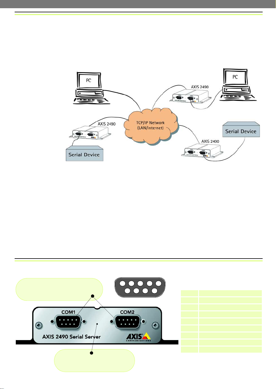
The AXIS 2490 Serial Server allows serial devices to connect directly to an Ethernet network
without using a PC, thus providing convenient remote access to these resources via HTTP
and TCP/IP. A few examples of physical setups using the AXIS 2490 are shown below:
❶ to ❸ The application
uses a network socket or a
COM-Port redirector to
communicate.
An application that uses a
local serial port will not
work with a networked
serial port. To make the
server’s port appear as a
local port on your PC, you
must install and use a
COM-Port Redirector.
❸
❷ to ❹ PC to Serial Server to network. Use this if you have
an old application that uses the serial port and
when you can’t use a COM-port redirector.
❶
❷
❹
❸ to ❹Two serial devices connect to
each other via a “virtual extension
cable”.
Ports
The AXIS 2490 is used for connecting serial ports to a network via the following:
• Two RS-232 serial ports on 9-pin male DSUB
• One 4-wire RS422 serial port on screw terminal block. This can also be used as a 2-wire
RS-485 port (direction controlled by RTS signal)
Each serial port operates independently of the others and can be used in these modes:
• Generic TCP/IP – used for communication using network sockets, with a COM-Port
redirector, or for tunnel communication between two serial devices or between a serial
device and a PC
• Generic HTTP – allows access via network browser (Netscape 4.x or Internet Explorer 4.x)
The Front Panel
RS-232 serial ports, 9-pin male D-SUB.
Both ports support: RX, TX, RTS, CTS, DSR,
DTR, RI and CD.
Control Button
The Control Button is used to reset the
unit to its default factory settings.
2714
3
5
8
96
Pinouts for the RS-232 port
Pin Function
1
2
3
4
5
6
7
8
9
I CD (Carrier Detect)
I RXD (Receive Data)
O TXD (Transmit Data)
O /DTR (Data Terminal Ready)
- GND (Ground)
I /DSR (Data Set Ready)
O /RTS (Request To Send)
I /CTS (Clear To Send)
I /RI (Ring Indicator)
Page 3

AXIS 2490 Getting Started Guide Page 2 of 5
The Rear Panel
Status Indicator
The yellow Status Indicator shows the unit’s operational
status, as described below:
• slow flash - indicates normal operation
• rapid flash - indicates a hardware failure
For the Status Indicator’s behavior during a reset to the
factory default settings, see page 4.
Power Supply Connector
A single Jack socket (PS-B) for
connection of the AXIS 2490
power supply.
Power Indicator
Constantly lit = normal operation
The RS-485/422 port
A 4-wire RS-422/485 port (one TX pair and one combined RX/TX pair).
The RX port can be used for both RX and TX (controlled by RTS)
and can be used for half-duplex RS-485. The port can be used for:
• Full-duplex RS-422 (4-wire) or
• 4-wire RS-485 or
• Half-duplex RS-485 (2-wire)
The port is compliant with EIA RS-485 up to 1843200 bps.
Connections for RS-485/422 on Connector Block
1 - 9-24V AC or DC Power
2 - 9-24V AC or DC Power
3 - GND
4 - GND 100 Ohm (to GND via 100 Ohm resistor
5 - RX/TX -A
6 - RX/TX +B
7 - TX8 - TX+
Physical Connections on the 8 pole I/O
Connector Block
(Phoenix MC 1.5 - 3.81mm)
4 pins for RS422/485 TX+, TX-, RX+, RX-
1 pin for RS485/422 ground (connected to
GND with 100 ohm resistor)
1 pin for GND
2 pins for alternative power (9-24V AC or DC)
Network Connector
The AXIS 2490 is designed for 10
Mbps Ethernet and 100 Mbps
Fast Ethernet networks and connects to the network via a
twisted pair category 5 cable
(10baseT and 100baseTX) terminated using a standard RJ-45
connector. Supporting NWAY,
the AXIS 2490 detects the speed
of the local network segment
and varies the speed of data
communication accordingly,
between 10 Mbps and 100 Mbps.
Page 4

AXIS 2490 Getting Started Guide Page 3 of 5
Connecting the AXIS 2490 to the Network
Follow the guide below to quickly connect your AXIS 2490 to an Ethernet network:
❶Note the serial number on the underside of the
unit. You need to know this to set the IP address:
❷Using an appropriate method for your
operating system, assign your product with a
unique IP Address from a computer on your
network, as follows:
Windows 95, 98, NT and 2000 only - Start a DOS
window and type these commands:
UNIX only - Type these commands
in the command line:
Serial number same as
Ethernet number; e.g.
00408c100086 =
00-40-8c-10-00-86
Syntax:
arp -s <AXISServer IP address> <Ethernet address>
<my PC IP address>
ping -t <AXISServer IP address>
Example:
arp -s 172.21.1.200 00-40-8c-10-00-86 172.21.1.193
ping -t 172.21.1.200
Syntax:
arp -s <IP address> <Ethernet address>
temp
ping <IP address>
Example:
arp -s 172.21.1.200 00:40:8c:10:00:86
temp
ping 172.21.1.200
Note: In some Unix systems, the arp command can be located in a directory that is not on the
command path; e.g: /usr/sbin/arp.
You will now see
Network
connector
❺10-15 seconds after connecting the power supply, the message
‘Reply from 172.21.1.200...’ - or similar, is returned
within the window. Ensure that the Power Indicator is permanently
lit and that the Status Indicator flashes slowly.
‘Request timed out ...’ messages repeatedly returned in the window.
❸Connect an Ethernet cable to your AXIS 2490
and attach it to the network.
❹Connect the external Power Supply to
the unit and connect it to your main
power supply.
RJ-45 connector
Power Connector
Status Indicator
Power Indicator
❻Exit Ping. The installation is now complete, and you are
ready to access the AXIS 2490 from your browser.
❼Verify the connection to the AXIS 2490 by starting your
browser and entering the IP address in the location/address
field, e.g. 171.21.1.200. You should then see the AXIS 2490’s
Welcome page displayed.
❽ You can now set up your application using the AXIS 2490. For more information,
see page 1 of this guide, or see the User’s Manual.
Page 5

AXIS 2490 Getting Started Guide Page 4 of 5
Refining the Installation
Click the Installation Wizard button. The wizard helps you complete the remaining
installation steps. For further configuration, click the Admin button. The buttons on the
Admin page provide access to general settings, port settings and settings for the network.
On-line
Help
Admin
Button
Installation
Wizard
Click the
icon to
configure
The mode
currently
selected
The information and screen examples shown here provide a very brief introduction to
configuring your AXIS 2490. For more detailed information, please refer to the AXIS 2490
User’s Manual, which can be obtained from www.axis.com.
Reinstating the Factory Default Settings
In certain circumstances, it may be necessary to reinstate the Factory Default settings for
your AXIS 2490. This is performed by clicking the appropriate button within the
Administration Tools, or by pressing the Control Button. Follow the instructions below to
reinstate the product factory default settings using the Control button:
1. Switch off the AXIS 2490 by disconnecting the power cable.
2. Press the Control Button and keep it pressed. Reconnect the power supply cable.
3. With the Control button pressed, the Status Indicator will now flash briefly and then go out.
When the Status Indicator has been out for about 5 seconds, release the Control Button. When
the Status Indicator starts to flash again after approximately 5 seconds, the AXIS 2490 will then
have been reset to its default settings.
Note: Reinstating the original default settings will cause all parameters (including the IP address) to be
reset.
Page 6

AXIS 2490 Getting Started Guide Page 5 of 5
Troubleshooting
Symptoms Possible causes Remedial actions
The AXIS 2490 cannot be
accessed from a browser.
The IP address is already used
by another device.
The IP address is located on a
different subnet.
In Windows 95, the ARP
table was empty when you
tried to set the IP address.
Proxy server. Try disabling the proxy default in your browser.
Other networking problems. Try replacing your network cable.
Disconnect your AXIS 2490 from the network, run the PING utility and
follow the appropriate recommendations.
Run the PING utility. If the utility returns “no response” or similar, in
Windows 95/98 or Windows NT/2000, you should then check that the
IP address for your AXIS 2490 is on the same subnet as your
workstation.
If these subnets are different, the IP address cannot be set from the
workstation. Please contact your network administrator.
If the table is empty, re-install the product, ensuring that the IP
address for your own PC is also used. Type
table.
Test the network interface of the product by connecting a local
computer to the unit, using a standard Crossover (hub-to-hub) Cable.
If the above actions don’t solve the problem, the AXIS 2490 may be
faulty. In this case, try to localize the problem by connecting the AXIS
2490 to the serial port of a local computer, using a Null Modem Cable
and report your findings to your local distributor.
arp -a to view the ARP
The Power indicator is not
constantly lit.
The Status indicator flashes
rapidly.
Your AXIS 2490 works
locally, but not externally.
"Unable to connect to
remote host: Connection
refused" or similar error
message.
An established connection is
immediately closed.
Faulty power supply. Verify that you are using an AXIS PS-B power supply.
Hardware failure. Contact your Axis dealer.
Firewall protection. Check the Internet firewall with your system administrator.
Default routers required. Check if you need to configure the default router settings.
The IP settings in the 2490
are wrong.
The TCP port number is
wrong.
The 2490 is not in Generic
TCP/IP mode.
Someone else is already
using the port and has
connected to the Axis 2490.
You have enabled "Allowed
IP addresses" but your IP
address is not allowed.
Check the IP number, router and netmask settings.
Make sure you use the same port number the 2490 is configured for.
Check the settings in the 2490.
Select "View Log FIle" in the Server settings to see if anyone else has
connected. You may want to configure "Allowed IP addresses" and
restart the unit.
Check the settings in the 2490.
Note: If you still have a problem after reading this information, please contact your reseller or
check the AXIS 2490 product pages at www.axis.com. The complete manual for the AXIS
2490 can also be obtained here.
Part No. 18627 R1.1
 Loading...