

Page 1

AXIS 2191 Audio Module
Sight, Speech and Sound — over IP!
In st a ll a ti o n Gu i de
Page 2
AXIS 2191 Installation Guide Page 1 of 7
The AXIS 2191 Audio Module
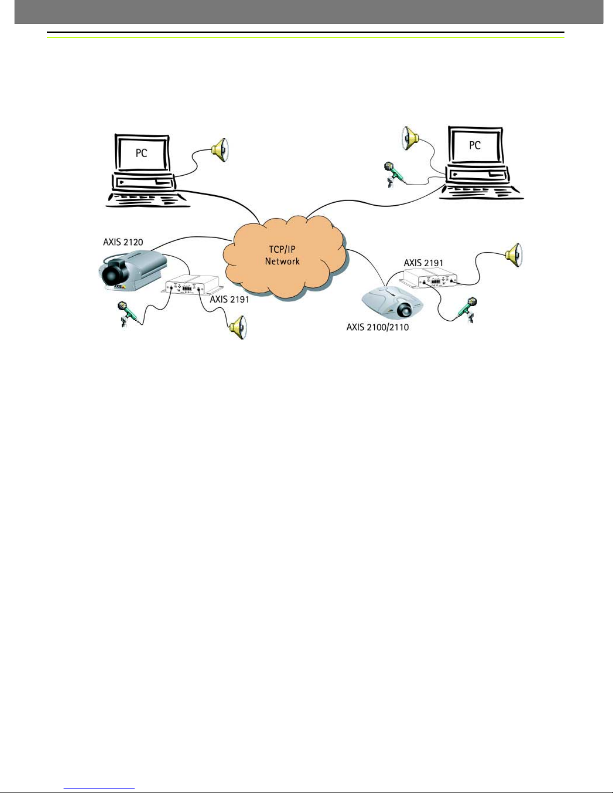
The AXIS 2191 Audio Module is an add-on device that provides audio capability to Axis network
cameras. The module connects quickly and easily to the serial port of the camera and is configured
and controlled via the camera’s user interface.
❶
❷
❹
❸
An Axis network camera (❸ or ❹) with an AXIS 2191 Audio Module connected provides live audio and video to browser clients (❶
and ❷) on the network.
Features and Functions
• Easy to install and use
• Runs on Ethernet LANs and/or the Internet
• Built-in omni-directional microphone
• Compatible with most microphones and speakers (not included)
• External microphone via 3.5mm socket or Line-In via the terminal block
• Simple configuration and management via the network camera’s administration pages
• Can be used in Full-Duplex, Half-Duplex or Simplex mode (see page 5)
• Push-to-talk button in client user interface in Half-Duplex or Simplex - Talk mode
• Fully adjustable input and output levels
•Mute function
Legal Considerations
Video and audio surveillance may be prohibited by laws that vary from country to country. Please
check the laws in your local region before using Axis network cameras or the AXIS 2191 Audio
Module for surveillance purposes.
Page 3
AXIS 2191 Installation Guide Page 2 of 7
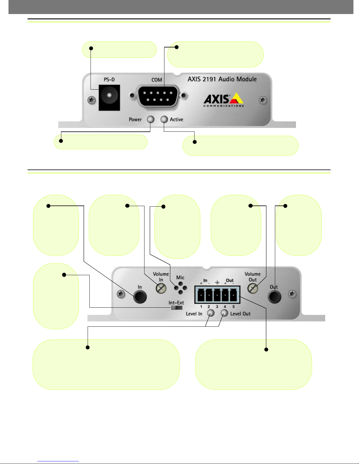
The Front Panel
Power Connector
Power Indicator - Normally lit.
The Rear Panel
In
3.5mm socket
for connection
of external
microphone.
Volume In
Level control for
input. Use a
screwdriver to
adjust.
Serial Port Connector - Connect
the serial cable from here to the serial
port on the camera.
Activity Indicator - Lights up when the
camera has configured the audio module.
Mic
Built-in omnidirectional
microphone.
Volume Out
Level control for
speaker volume.
Use a screwdriver to adjust.
Line Out
3.5mm socket
for speakers
with built-in
amplifier, e.g.
PC speakers.
Int-Ext
Set to Int for
internal microphone or Ext
for external
microphone or
Line-In.
Level In/Level Out
The colors used to indicate the input and output levels are:
• Green - Level OK
• Yellow - Risk for overload
•Red - Overload
Terminal Block Connector
Used for:
• Line-In (e.g. CD, radio)
• Speaker-out (headphones or speakers
without amplifier)
Page 4

AXIS 2191 Installation Guide Page 3 of 7
Installing the Audio Module
Follow the guide below to quickly get your AXIS 2191 up and running. Refer to the illustrations on
the previous page for connector details.
❶ Before you start the installation of the AXIS 2191 Audio Module, you must first install your
network camera. To do this, please refer to the documentation supplied with your camera. If you
intend running the audio module in full-duplex mode, check that the sound card on your computer
supports this.
❷ If using an external microphone, connect it to
the socket provided. To use an alternative input
device, (e.g. CD-player or radio) connect it to
Line-In on the terminal block.
❸ Set the selector switch
to Ext to use an external
microphone or device.
Otherwise, set to Int to use
the internal microphone.
❺ Using the supplied cable, connect the
audio module’s serial port to the network
camera’s serial port.
❻ Connect power
to the audio module.
❼ Check that the power indicators on both the audio module and the
camera are lit. Note that the power LED will blink during power-up.
❽ Using a screwdriver,
adjust the Volume In con-
trol so that the Level In
LED occasionally shows
yellow, but not red.
❹ Connect a loudspeaker to the 3.5mm socket (amplified speakers
only), or to Out on the terminal block (speakers with no amplification). Other devices (including headphones) are connected to the
terminal block.
❾ To verify the connection to the AXIS 2191,
start Internet Explorer and enter the IP address
of the network camera in the location/address
field, e.g. 171.1.2.200, as shown here. Configure
the audio module from the camera’s administration pages, as described in the following
section.
Page 5

AXIS 2191 Installation Guide Page 4 of 7
Configuring the Audio Module
The network camera’s administration pages provide all the tools required for successfully configuring
the AXIS 2191. From the camera’s home page, click on the link to Administration Tools. A new page
containing the tools will open. To complete the configuration of your audio module, follow these
instructions:
1. From the Admin tools, click External Devices. Select the
AXIS 2191 Audio Module as the device to use. Click Save.
Note: If you do not see External Devices, then your camera
does not have the correct firmware installed and it must be
upgraded.
2. Under External Devices, click Audio. This opens the
configuration page for the audio module (see illustration
Admin
tools
below).
3. Select the audio mode. This can be:
• Full-Duplex (Talk and Listen simultaneously)
• Half-Duplex (Talk and Listen)
• Simplex - Talk
• Simplex - Listen
This selection will depend on your application. See page 5 for more information.
4. Enter the number of clients that will be able
to access the application at any one time.
Use this setting to limit access if you only
have limited bandwidth available.
5. If you are using Half-Duplex mode, the
Send option can be used to send audio from
the client currently transmitting to all the
other clients, and not just to the server end.
Set to Yes to enable the function.
6. When using Half-Duplex mode, the Push-
To-Talk button will be visible. Select the
mode to use for this button. Selecting
Toggle means that when the button is
pushed it will remain so until pushed a
second time. Instant means that the button
will remain active (pushed) until released.
The configuration page for the AXIS 2191.
7. Adjust the Volume Out control until a
satisfactory speaker level is heard. The
Level Out LED can be used to check that
there is audio being received. Note that
both the control and the LED are on the
audio module itself.
Page 6

AXIS 2191 Installation Guide Page 5 of 7
Using the Audio Module with Your Camera
Your audio module is now configured and ready for use with your network camera. Enter your
camera’s IP-address in Internet Explorer, or click Home on the camera’s admin page. You should then
see the control panel for the AXIS 2191 below the camera image. If no audio controls are visible,
check that you have made the correct setting under External Devices.
NB. Exactly which controls will be
visible below the image depends
on the audio mode you are using.
For example, the Push-to-Talk
button will not be visible in Full-
Push-To-Talk
Used in Half-Duplex or
Simplex - Talk mode.
The button’s own
mode is set in the
camera’s admin pages.
Duplex mode. Similarly, when
using Simplex - Listen mode, only
the Speaker controls will be
shown. The audio mode is set in
the camera’s admin tools.
Available Bandwidth
Select the bandwidth available
for your connection.
Show/Hide Settings
Shows or hides the
slider controls and
level indicators
Level Adjust IN/OUT
Drag sliders to adjust level.
Mute Checkboxes
Check to mute speaker or microphone.
Using the Different Audio Modes
Full-Duplex
Full-Duplex mode means that you can transmit and receive audio (talk and listen) at the same time,
without having to use any of the controls. This is just like having a telephone conversation. The only
controls you may wish to use are the mute checkboxes to turn off the sound, and the level sliders, to
adjust the input/output levels. This mode requires a full-duplex sound card on your computer. If your
available bandwidth is 0.2Mbit/s or less, it is recommended that you use Half-Duplex mode instead.
Half-Duplex
Half-Duplex mode also sends and receives audio in both directions, but only in one direction at a
time. This means you must actively transmit with the help of the Push-to-Talk button. To speak,
press the button (check that the microphone is not muted). When finished speaking, release the
button. You will now be receiving audio from the other end of the connection. Note that the Push-toTalk button can be configured for use in two different ways - Toggle or Instant. This is set in the
camera’s admin tools. Half-Duplex mode is best if you only have limited bandwidth available.
Simplex - Talk
Simplex - Talk mode means that only the web-client end of the connection can transmit audio (that
is, to the AXIS 2191). This could be used, for example, to provide spoken instructions to a person seen
in the network camera. This mode also requires you to use the Push-to-Talk button.
Simplex - Listen
Simplex - Listen mode can only receive audio from the AXIS 2191 to the web-client. This can be used
in remote monitoring, web attractions etc., to provide live audio, as well as video, of a monitored
situation.
Page 7

AXIS 2191 Installation Guide Page 6 of 7
Troubleshooting
Symptoms Possible causes Remedial actions
The network camera cannot
be accessed from a browser.
No audio controls below
camera image.
No sound from the AXIS
2191 or from a PC trying to
access a web page
containing audio content.
No audio signal from PC to
the AXIS 2191 when passing
a proxy server.
No full-duplex function. Incorrect configuration. Check the setting in the camera’s administration tools. See also page 4.
Poor performance. Too many users/clients
Whining or screeching sound
from speakers (feedback).
Poor sound on headphones. Incorrect connection. Headphones can only be used by connecting them to Speaker-Out on
The Power indicator LED is
not constantly lit.
Your AXIS 2191 works
locally, but not externally.
Incorrect camera
configuration.
Networking problems. Check all cables, including the network cable from the camera to the
The AXIS 2191 is not selected
as the external device.
Wrong camera firmware. Check the firmware in the camera by checking if External Devices
Incorrect settings or faulty
connections.
The Post Content Length set
in the proxy server is too low.
Sound card does not support
full-duplex.
connected.
Low bandwidth. Reduce the available bandwidth by changing to a lower setting in the
Poor positioning of speakers
and/or microphone.
Faulty power supply. Verify that you are using an AXIS PS-D power supply.
Firewall protection. Check the Internet firewall with your system administrator.
Default routers required. Check if you need to configure the default router settings.
Please refer to the camera’s documentation for help on resolving the
problem.
network. See the camera’s documentation.
In the camera’s administration tools, click on External Devices and
select the AXIS 2191 Audio Module.
appears in the camera’s Administration Tools. If not, the camera does
not have the correct firmware and it must be upgraded.
Check that:
• soundcard, speakers and microphone are connected
• the Mute button is not pressed
• the Int/Ext switch for the input is in the correct position
• the input and output levels are correct
• all cabling is connected and all power switches are ON
Set the value of the Post Content Length in your proxy server to 1MB or
more. You may need to contact your system administrator to do this.
For information on how to check if your sound card supports fullduplex, please visit www.axis.com and see the support section for Axis
camera products.
Try limiting the number of clients allowed to connect.
Available Bandwidth selector. Setting a lower bandwidth will reduce
any break-up in the sound, but will also increase the transmission
delay.
If running in Full-Duplex mode, try switching to Half-Duplex mode.
Relocate the speakers or microphone so that they do not point towards
each other, and/or lower the volume.
the terminal connector.
Note: If you still have a problem after reading this information, please contact your reseller, or
visit www.axis.com and check the support section for Axis camera products.
Page 8

AXIS 2191 Installation Guide Page 7 of 7
Technical Specifications
• Operating temperature: 40-105
o
(5-40
C).
• Humidity - 8-80% relative humidity.
• EMC - : EN55024, EN55022, Class B and
EN61000-3-3.
• EMC - FCC Class A of FCC Rules and Regulations part 15, subpart B.
•EMC -
• Full-duplex audio: Audio data encoded in
ADPCM format at 32kbps, 8 kHz sampling
(G.721). Data is sent using HTTP.
• 9-pin D-SUB serial connector: RS-232.
• Power Input: Axis PS-D power supply.
• Microphone Input: 1-50mVpp. PC type.
o
F
• Line Out: Unbalanced, 0.05-1.0Vpp
• Line Input: Balanced 0.05-1Vpp. Connect
source ground to pin 2 and source signal to
pin 1 if the source is unbalanced.
• Speaker Output: Balanced, 0.5W. Impedance
8-32 Ohms. Connect directly to speaker without capacitors.
• Alternative Power: 12-15VAC, min 10VA, or
15-20VDC, min 7W.
• Metrics: Height: 1.1” (27mm),
Width: 4.4” (112mm), Length: 4.3” (110mm),
Weight: 0.7lb (0.32kg).
• Maximum number of users: 10 (on local
area network).
Connection Diagram
The Audio Module to Camera Serial Cable
The serial cable supplied with your AXIS 2191 is wired as shown in the table below:
Pinouts for the RS-232 Port
Audio Pin Pin Camera Signal
IN 1 1 IN CD
IN 2 2 IN RXD
OUT 3 3 OUT TXD
OUT 4 4 OUT DTR
GND 5 5 GND GND
IN 6 6 IN DSR
OUT 7 7 OUT RTS
IN 8 8 IN CTS
Unused 9 9 IN RI
Part No. 18692 v1.0
 Loading...