


f
or
C O M M U N I C A T I O N S
PRODUCT INSTRUCTIONS
MODEL:
21898
Before attempting to connect or operate this product,
please read these instructions completely.
81-IN6217R3

!
!
SAFETY PRECAUTIONSIMPORTANT SAFEGUARDS
1. Read Instructions - All the safety and operating instructions
should be read before the unit is operated.
2. Retain Instructions - The safety and operating instructions
should be retained for future reference.
3. Heed Warnings - All warnings on the unit and in the operating
instructions should be adhered to.
4. Follow Instructions - All operating and user instructions should
be followed.
5. Electrical Connections - Only a qualified electrician should make
electrical connections.
6. Attachments - Do not use attachments not recommended by the
product manufacturer as they may cause hazards.
7. Cable Runs -All cable runs must be within permissible
distance.
8. Mounting - This unit must be properly and securely mounted to
a supporting structure capable of sustaining the weight of
the unit. Accordingly:
a. The installation should be made by a qualified installer.
b. The installation should be in compliance with local codes.
c. Care should be exercised to select suitable hardware to install the
unit, taking into account both the composition of the mounting
surface and the weight of the unit. Be sure to periodically
examine the unit and the supporting structure to make sure
that the integrity of the installation is intact. Failure to comply
with the foregoing could result in the unit separating from the
support structure and falling, with resultant damages or injury
to anyone or anything struck by the falling unit.
DOME/HOUSING/ELECTRICAL COMPONENT
WARRANTY INFORMATION
Axis, Incorporated warrants that its domes and housing
sold here under shall be fit for the ordinary purpose for which
said products are intended and shall be free from defects in
material and workmanship for a period of three years from date
of sale to buyer. Note that all electrical components will be
warranted for a period of three years from date of sale to buyer.
Axis makes no other warranty of any kind with respect
to this product, whether expressed or implied, including,
without limitation, the implied warranty of fitness for a particular
purpose.
In the event of a breach of the above warranty, Axis shall,
at its option, repair or replace said product. This is Axis's
sole obligation under this warranty. In no event shall Axis
be liable for any incidental or consequential damages, as
defined in section 2-715 of the Uniform Commercial Code by a
breach of this warranty.
Axis shall repair or replace defective products upon
shipment of products returned prepaid to Axis.
Repairs made necessary by reason of accident, misuse or
normal wear shall be charged at Axis's standard rate.
This warranty gives you specific legal rights, and you may also
have other rights which vary from state to state.
UNPACKING
Unpack carefully. Electronic components can be damaged if
improperly handled or dropped. If an item appears to have been
damaged in shipment, replace it properly in its carton and notify
the shipper.
Be sure to save:
1. The shipping carton and packaging material. They are the safest
material in which to make future shipments of the equipment.
2. These Installation and Operating Instructions.
SERVICE
If the unit ever needs repair service, the customer should contact
Axis (1-800-444-2947) for authorization to return and
shipping instructions.
TECHNICAL SUPPORT
If technical support is needed, Axis has set-up a
technical support
1-800- 444-2947
CAUTION: TO REDUCE THE RISK OF ELECTRICAL SHOCK,
DO NOT OPEN COVERS.
NO USER SERVICEABLE PARTS INSIDE.
REFER SERVICING TO QUALIFIED SERVICE PERSONNEL.
The lightning flash with an arrowhead symbol,
with in an equilateral triangle, is intended to alert the
user to the presence of non-insulated "dangerous
voltage" within the product's enclosure that may
be of sufficient magnitude to constitute a risk of
electric shock to persons.
The exclamation point with in an equilateral triangle
is intended to alert the user to presence of important
operating and maintenance (servicing) instructions
in the literature accompanying the appliance.
AXIS TECHNICAL SUPPORT
C AUTION
R ISK OF
ELECTRIC SHOCK !
line for their customers.

Electrical Specifications
!!
Power 24VAC
Class 2 Power Supply Only
Tools Required: Phillips Head Screwdriver
English
Ceiling Support Wires(18-24 Gauge Wire)
Energía 24VAC
Fuente De Alimentación De la Clase 2
Solamente
Español
Herramientas Requeridas: Destornillador
Principal Phillips
Alambre De la Galga De la Ayuda
Wires(18-24 Del Techo)
Puissance 24VAC
Alimentation D'Énergie De la Classe 2
Seulement.
Français
Outils Requis : Tournevis Principal Phillips
Fil De Mesure De Soutien Wires
(18-24 De Plafond)
21898
Deutsch
Portuguese
Italiano
Energie 24VAC
Nur Kategorie 2 Spg.Versorgungsteil
Werkzeuge Erfordert:
Kreuzkopfhauptschraubenzieher
Decke Unterstützungswires
(18-24 Lehre Leitung)
Poder 24VAC
Fonte De Alimentação Da Classe 2 Somente
Ferramentas Requeridas: Chave de fenda
Principal Phillips
Fio Do Calibre Da Sustentação
Wires(18-24 Do Teto)
Alimentazione 24VAC
Gruppo di alimentazione Del Codice
categoria 2 Soltanto
Gli Attrezzi Hanno richiesto: Cacciavite
Capo "phillips"
Legare Del Calibro Di Sostegno
Wires(18-24 Del Soffitto)

Using the provided template, mark the
ceiling tile for the cutout.
• Con la plantilla proporcionada, cortar el azulejo del techo
para el agujero.
• En utilisant le calibre fourni, marquez la tuile de plafond
pour le coupe-circuit.
• Mit der zur Verfügung gestellten Schablone kennzeichnen
Sie die Decke Fliese für den Ausschnitt.
• Usando o molde fornecido, marque a telha do teto para o
entalhe.
• Usando la mascherina fornita, contrassegni le mattonelle
del soffitto per il ritaglio.
A box cutter or jigsaw can be used for
cutting the circle.
•
Un cortador o un rompecabezas de la caja se
puede utilizar para cortar el círculo.
•
Un coupeur ou une scie sauteuse de boîte peut
être utilisé pour couper le cercle.
•
Ein Kastenscherblock oder -tischlerbandsäge
können für den Schnitt des Kreises benutzt werden.
•
Um cortador ou um jigsaw da caixa podem ser
usados cortando o círculo.
•
Una taglierina o un jigsaw della scatola può essere
utilizzato per il taglio del cerchio.
1
2
(2) locations
3
for the conduit
Remove the desired conduit knock-out
from the top of the housing.
• Quite la maravilla deseada del conducto de la
tapa de la cubierta.
• Enlevez l'éjecteur désiré de conduit du dessus du
logement.
• Entfernen Sie den gewünschten Rohr Knock-out
von der Oberseite des Gehäuses.
• Remova o knock-out desejado da canalização
do alto da carcaça.
• Rimuova l'espulsore voluto del condotto dalla
parte superiore dell'alloggiamento.
4
Fit the flex conduit or ‘L’ counduit into the
desired hole.
• Quepa el conducto o el ` L ' counduit de la
flexión en el agujero deseado.
• Adaptez le conduit ou le ` L 'counduit de câble
dans le trou désiré.
• Passen Sie das Flexrohr oder das ` L ' counduit in
die gewünschte Bohrung.
• Caiba a canalização do cabo flexível ou o ` L '
counduit no furo desejado.
• Misura il condotto della flessione o il ` la L 'counduit nel foro voluto.
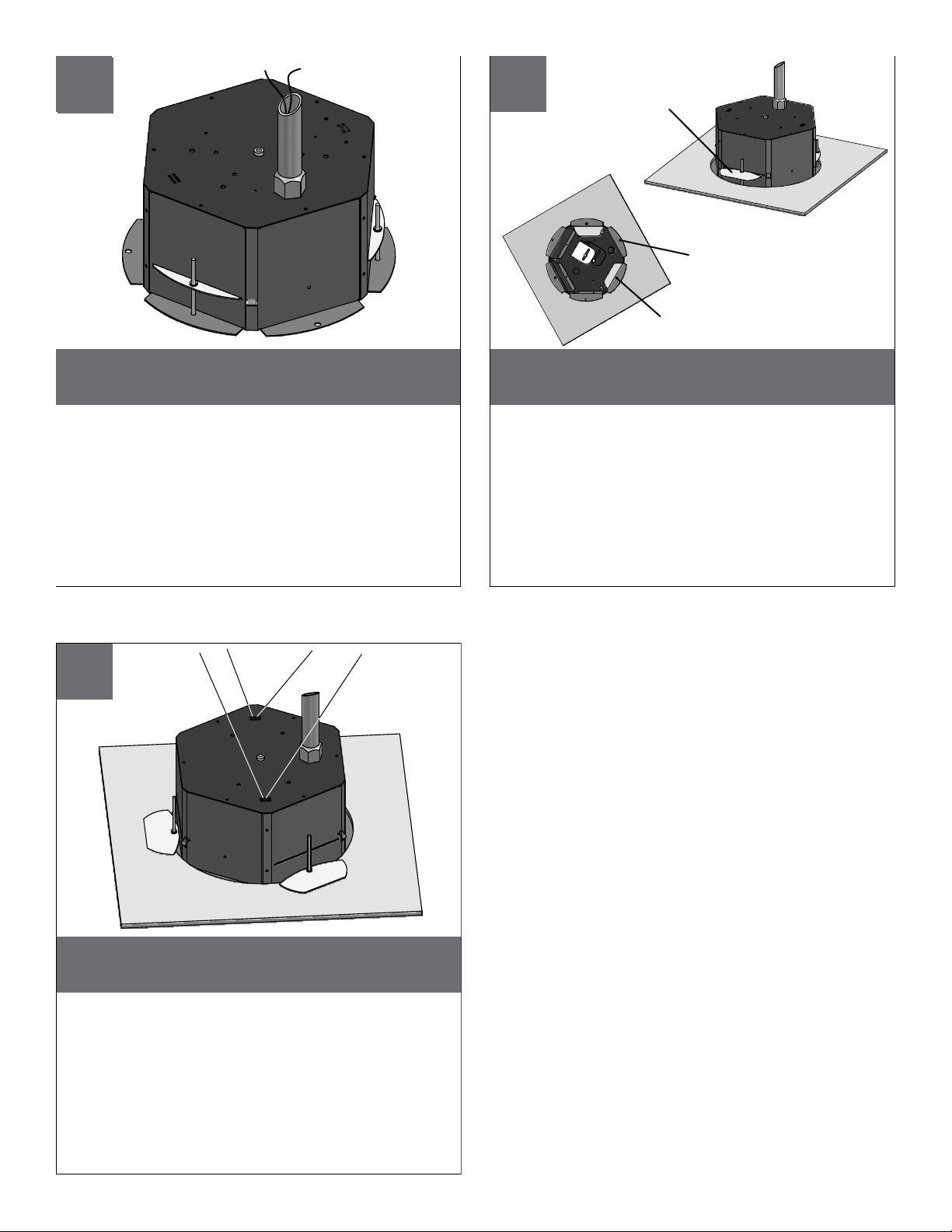
5
6
Support
Support
Arms Rotate
Arms Rotate
Out
Out
Support Arm
Holes
Mounting
Holes
Run electrical cable into the housing
through the conduit.
• Funcione el cable eléctrico en la cubierta a
través del conducto.
• Courez le câble électrique dans le logement par
le conduit.
• Lassen Sie elektrisches Kabel in das Gehäuse
durch das Rohr laufen.
• Funcione o cabo elétrico na carcaça através da
canalização.
• Faccia funzionare il cavo elettrico
nell'alloggiamento tramite il condotto.
7 8
With the bottom flange pressed against the ceiling,
rotate support arms to the outside. Tighten the support
arm screws.
•
Con el fondo el reborde presionó contra el techo, rota los brazos de
ayuda al exterior. Apriete los tornillos del brazo de ayuda.
•
Avec le fond la bride a serré contre le plafond, tournent des bras de
soutien jusqu à l'extérieur. Serrez les vis de bras de soutien.
• Mit Unterseite betätigte sich der Flansch gegen die Decke, drehen
Lagerarme zur Außenseite. Ziehen Sie die Lagerarmschrauben fest.
• Com fundo a flange pressionou de encontro ao teto, gira os braços
de sustentação à parte externa. Aperte os parafusos do braço de
sustentação.
• Con la parte inferiore la flangia ha premuto contro il soffitto, ruota
l'armi di sostegno alla parte esterna. Stringa le viti del braccio di
sostegno.
If required, secure housing by running bolts in the
bottom flange and support wires from a solid structure.
Si está requerido, asegure los pernos del funcionamiento de la
•
cubierta en el reborde inferior y apoye los alambres de una
estructura sólida.
•
S'il y a lieu, fixez les boulons de course de logement dans la bride
inférieure et soutenez les fils d'une structure pleine.
• Wenn erforderlich sichern Sie Gehäusedurchlaufschraubbolzen im
unteren Flansch und stützen Sie Leitungen von einer festen Struktur.
• Se requerido, fixe os parafusos do funcionamento da carcaça na
flange inferior e suporte fios de uma estrutura contínua.
• A richiesta, assicuri i bulloni di funzionamento dell'alloggiamento nella
flangia inferiore e sostenga i legare da una struttura solida.
8
17
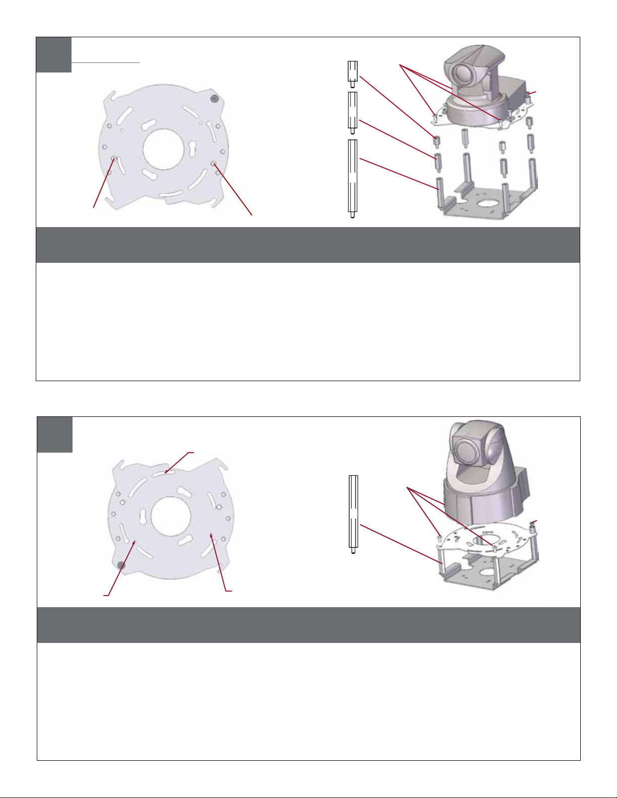
Axis 213
Mounting Plate
(13mm) ½"
(26mm) 1"
(52
mm
) 2"
(3) #8x3/8”
Captive
Screw
MOUNTING HOLE
MOUNTING HOLE
Install the camera to the mounting plate with (2) #10 screws and lock washers provided. Place (3)
#8x3/8” screws on the spacers and align the mounting slots. Slide on plate and camera then secure.
• Instale la cámara fotográfica a la placa de montaje con (2) los tornillos #10 y las arandelas de cerradura proporcionadas. Coloque los
tornillos de (3) del # 8x3/8"en los espaciadores y alinee las ranuras de montaje. Resbale en la placa y la cámara fotográfica entonces
seguras.
• Installez l'appareil-photo sur le plat de support avec (2) les vis #10 et les rondelles de freinage fournies. Placez les vis de (3) # de 8x3/8"
sur les entretoises et alignez les fentes de support. Glissez du plat et de l'appareil-photo puis bloqués.
• Bringen Sie die Kamera zur Montageplatte mit (2) den bereitgestellten Schrauben #10 und Federringen an. Setzen Sie (3) # 8x3/8"die
Schrauben auf die Distanzscheiben und richten Sie die Befestigungsschlitze aus. Schieben Sie auf die sichere Platte und Kamera dann.
• Instale a câmera à placa de montagem com (2) os parafusos #10 e as arruelas de fechamento fornecidas. Coloque os parafusos de
(3) # de 8x3/8"nos espaçadores e alinhe os entalhes de montagem. Deslize na placa e na câmera então seguras.
• Installi la macchina fotografica al giunto di supporto con (2) le viti #10 e le ranelle di bloccaggio fornite. Disponga le viti di 8x3/8"# di (3)
sui distanziatori ed allinei le scanalature di montaggio. Faccia scorrere sulla piastra e sulla macchina fotografica allora sicure.
9
Axis 214
Mounting Hole
3026 Mounting
(3) #8 x 3/8”
18
Plate
Captive
Screw
Mounting
Hole
(52mm) 2"
Mounting
Hole
Install the camera to the mounting plate using (3) 3mm x 12mm bolts and lock washers. Place (3) #8x3/8”
screws on the spacers and line up the mounting slots. Slide plate in and secure.
• Instale la cámara fotográfica a la placa de montaje usando (3) los pernos de 3m m x de 12m m y las arandelas de cerradura.
Coloque los tornillos de (3) del # 8x3/8"en los espaciadores y alinee las ranuras de montaje. Resbale la placa adentro y
asegúrela.
• Installez l'appareil-photo sur le plat de support en utilisant (3) des boulons de 3mm x de 12mm et des rondelles de freinage.
Placez les vis de (3) # de 8x3/8"sur les entretoises et alignez les fentes de support. Glissez le plat dedans et le fixez.
• Bringen Sie die Kamera zur Montageplatte mit (3) 3mm x 12mm den Schraubbolzen und den Federringen an. Setzen Sie (3) #
8x3/8"die Schrauben auf die Distanzscheiben und richten Sie die Befestigungsschlitze aus. Schieben Sie Platte innen und sichern
Sie.
• Instale a câmera à placa de montagem usando (3) os parafusos de 3mm x de 12mm e as arruelas de fechamento. Coloque os
parafusos de (3) # de 8x3/8"nos espaçadores e alinhe-os acima dos entalhes de montagem. Deslize a placa dentro e fixe-a.
• Installi la macchina fotografica al giunto di supporto usando (3) i bulloni di 12mm x di 3mm e le ranelle di bloccaggio. Disponga
le viti di 8x3/8"# di (3) sui distanziatori ed allinei le scanalature di montaggio. Faccia scorrere la piastra dentro e fissi.
10
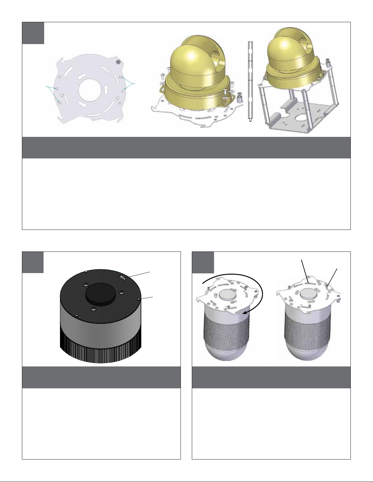
Axis 215
1"
1"
Mounting
Holes
Mounting
Holes
2"
Install the camera to the mounting plate with (4) #8 screws and lock washers provided. Place (3) #8x3/8”
screws on the spacers and align the mounting slots. Slide on plate and camera then secure.
• Instale la cámara fotográfica a la placa de montaje con (4) los tornillos #8 y las arandelas de cerradura proporcionadas. Coloque los
tornillos de (3) del # 8x3/8"en los espaciadores y alinee las ranuras de montaje. Resbale en la placa y la cámara fotográfica entonces
seguras.
• Installez l'appareil-photo sur le plat de support avec (4) les vis #8 et les rondelles de freinage fournies. Placez les vis de (3) # de 8x3/8"
sur les entretoises et alignez les fentes de support. Glissez du plat et de l'appareil-photo puis bloqués.
• Bringen Sie die Kamera zur Montageplatte mit (4) den bereitgestellten Schrauben #8 und Federringen an. Setzen Sie (3) # 8x3/8"die
Schrauben auf die Distanzscheiben und richten Sie die Befestigungsschlitze aus. Schieben Sie auf die sichere Platte und Kamera dann.
• Instale a câmera à placa de montagem com (4) os parafusos #8 e as arruelas de fechamento fornecidas. Coloque os parafusos de
(3) # de 8x3/8"nos espaçadores e alinhe os entalhes de montagem. Deslize na placa e na câmera então seguras.
• Installi la macchina fotografica al giunto di supporto con (4) le viti #8 e le ranelle di bloccaggio fornite. Disponga le viti di 8x3/8"# di (3)
sui distanziatori ed allinei le scanalature di montaggio. Faccia scorrere sulla piastra e sulla macchina fotografica allora sicure.
AXIS 231-232D
TAB
Locking screw
11
AXIS 231-232D
Tab
12
Loosen
Screw
Loosen the screw to the right of the tab by
approximately (5) turns.
• Afloje el tornillo a la derecha de la lengüeta aproximadamente (5) vueltas.
• Desserrez la vis à la droite de l'étiquette approximativement (5) aux tours.
• Lösen Sie die Schraube auf der rechten Seite des
Vorsprunges durch ungefähr (5) Umdrehungen.
• Afrouxe o parafuso à direita da aba aproximadamente (5) por voltas.
• Allenti la vite alla destra della linguetta circa (5) dalle
girate.
Align mounting plate and turn counter-
clockwise, secure locking screw.
• Alinee la placa de montaje y dé vuelta a la
izquierda, tornillo de fijación seguro.
• Alignez le plat de support et tournez dans le sens
contraire des aiguilles d'une montre, vis de blocage
bloquée.
• Richten Sie Montageplatte aus und drehen Sie nach
links, sichere Sicherungsschraube.
• Alinhe a placa de montagem e gire-a no sentido
anti-horário, parafuso travando seguro.
• Allinei il giunto di supporto e giri in senso antiorario, la
vite di bloccaggio sicura.

13
Axis 231-232D
ADD SPACERS
AND SCREWS
Attach the connection module as shown. Attach this assembly to the housing using
This is what the typical path of illumination will look like with the setting at 30 degrees.
(1) 6-32x3/8” screw and star washer.
• Una el módulo de la conexión según lo demostrado. Una a esta asamblea a la cubierta usando (1) "arandela del
tornillo 6-32x3/8 y de la estrella.
• Attachez le module de raccordement comme montré. Attachez cette assemblée au logement en utilisant (1) la "vis
6-32x3/8 et tenez le premier rôle la rondelle.
• Bringen Sie das Anschlußmodul an, wie gezeigt. Bringen Sie diese Versammlung zum Gehäuse mit (1) "Schraube
6-32x3/8 und Sternunterlegscheibe an.
• Una o módulo da conexão como mostrado. Una este conjunto à carcaça usando (1) do "arruela parafuso 6-32x3/8
e da estrela.
• Fissi il modulo del collegamento come indicato. Fissi questo complessivo all'alloggiamento usando (1) "rondella della
vite 6-32x3/8 e della stella.
Mounting Hole
14
Axis 233D
Mounting Hole
Remove power board located inside of housing and then remove mounting bracket.
• Quite a tablero de energía situado dentro de la cubierta y después quite el soporte de montaje.
• Enlevez carte d'alimentation situé à l'intérieur de du logement et puis enlevez le support.
• Entfernen Sie das Energie Brett, das innerhalb des Gehäuses befunden wird und entfernen Sie dann Schienenplatte.
Camera
Bracket
• Remova a placa de poder situada dentro da carcaça e remova então o suporte de montagem.
• Rimuova il bordo di alimentazione situato all'interno di alloggiamento ed allora rimuova il supporto di attacco.

17
Assemble Axis locking plate to quick release plate using (3) #8 bolts, washers and nuts. Connect the combined plates to
the bracket and housing using (4) 1” and (4) ½” spacers and #8 bolts. Insert camera onto mounted locking plate and turn
clockwise to lock in position.
• Monte la placa de fijación del eje la placa del lanzamiento rápido usando (3) los pernos #8, las arandelas y las tuercas. Conecte las placas combinadas con el
soporte y la cubierta usando (4) los espaciadores de 1” y (4) ½” y los pernos #8. Inserte la cámara sobre la placa de fijación montada y dé vuelta a la derecha a la
cerradura en la posición.
• Assemblez le plat de verrouillage d'axe au plat de dégagement rapide utilisant (3) les boulons #8, les rondelles et les écrous. Reliez les plats combinés à la parenthèse
et au logement utilisant (4) les entretoises de 1 » et (4) ½ » et les boulons #8. Insérez l'appareil-photo sur le plat de verrouillage monté et tournez dans le sens des
aiguilles d'une montre pour fermer à clef en position.
• Bauen Sie Verriegelungsplatte der Mittellinie zur Platte der schnellen Freigabe unter Verwendung (3) der Schraubbolzen #8, der Unterlegscheiben und der Nüsse
zusammen. Schließen Sie der kombinierten Platten an den Haltewinkel und das Gehäuse unter Verwendung (4) 1“ und (4) ½“ der Distanzscheiben und der
Schraubbolzen #8 an. Setzen Sie Kamera auf angebrachte Verriegelungsplatte ein und wenden Sie sich nach rechts an Verschluss in Position.
• Monte a placa de travamento da linha central à placa da liberação rápida usando (os parafusos 3) #8, as arruelas e as porcas. Conecte as placas combinadas ao
suporte e à carcaça usando (4) espaçadores de 1” e (4) ½” e parafusos #8. Introduza a câmera na placa de travamento montada e gire-a no sentido horário para o
fechamento em posição.
• Monti il piatto di chiusura di asse a usando del piatto del rilascio rapido (3) bulloni #8, rondelle e dadi. Colleghi i piatti uniti a usando dell'alloggiamento e della staffa
(4) i distanziatori del 1„ e (4) ½„ e bulloni #8. Inserisca la macchina fotografica sul piatto di chiusura montato e giri in senso orario verso la serratura nella posizione.
Axis P5534
(26mm) 1"
(13mm) ½"
(3) #8x3/8”
Captive
Screw
MOUNTING HOLE
Axis Locking Plate
Mounting Bracket
Quick Release Plate
15
Axis 233D
Install (4) 1/2” spacers (from bracket) to base bracket. mount camera bracket and install (4)
additional 1/2” spacers to camera bracket.
• Instale (4) los espaciadores del 1/2"(del soporte) para basar el soporte. monte el soporte de la cámara fotográfica
e instale (4) los espaciadores adicionales del 1/2"al soporte de la cámara fotográfica.
• Installez (4) les entretoises de 1/2"(de la parenthèse) pour baser la parenthèse. montez la parenthèse d'appareilphoto et installez (4) les entretoises additionnelles de 1/2"sur la parenthèse d'appareil-photo.
• Bringen Sie (4) die 1/2"Distanzscheiben (vom Haltewinkel) an um Haltewinkel zu gründen. bringen Sie Kamerahaltewinkel an und bringen Sie (4) die zusätzlichen 1/2"Distanzscheiben zum Kamerahaltewinkel an.
• Instale (4) espaçadores de 1/2"(do suporte) para basear o suporte. monte o suporte da câmera e instale (4)
espaçadores adicionais de 1/2"ao suporte da câmera.
• Installi (4) i distanziatori di 1/2"(dalla staffa) per basare la staffa. monti la staffa della macchina fotografica ed
installi (4) i distanziatori supplementari di 1/2"alla staffa della macchina fotografica.
16

Reattach the trim ring/ dome assembly by pressing in and sliding (3) springs in the
housing.
• Reate el montaje de la bóveda del anillo del ajuste clavando y resbalando (3) los resortes en la cubierta.
• Rattachez le dôme d'anneau d'équilibre en enfonçant et diapositive (3) des ressorts dans le logement.
• Befestigen Sie die Ordnung Ringhaube wieder, indem Sie (3) Federn im Gehäuse eindrücken und schieben.
• Reate o conjunto da abóbada do anel da guarnição pressionando dentro e deslizando (3) as molas na carcaça.
• Riattacci il complessivo della cupola dell'anello della cornice introducendo e diapositiva (3) le molle nell'alloggiamento.
17
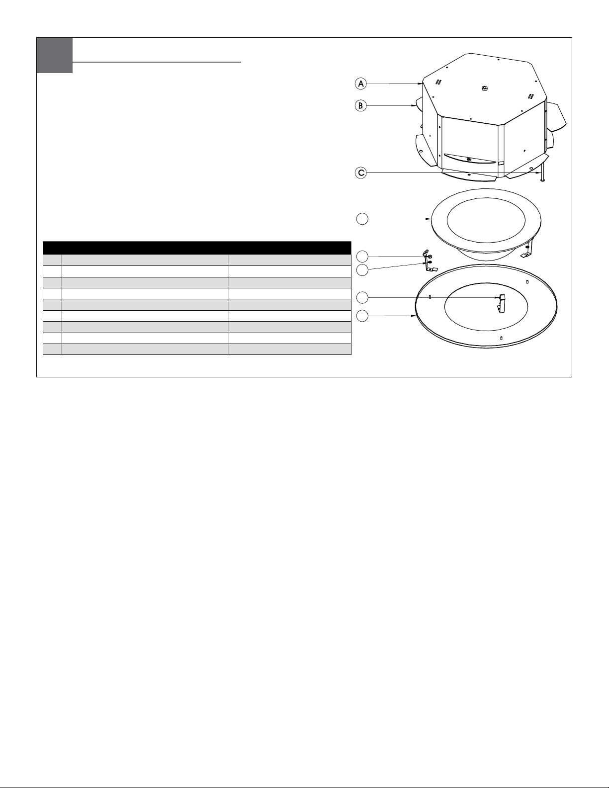
D
H
G
F
E
Description Part Number
A 21898 Top housing RPMR7010
B 21898 support arms RPMR7020
C 10-24 x 2.0" SS pan head screw 90-BTSR23
D 7" Tinted capsule, 21898 RC7AT
E 6-32 Hex nut SS 91-NTHH04
F #6 Star washer 92-WSTH01
G 21898 Spring clip 30-VL1222
H 21898 White trim ring RPMR7050
NS Hardware Packet RP46PHH2094
21898
Replacement Parts List
 Loading...