

Page 1

1
AXIS 216FD Pendant Kit
Installation Guide
ENGLISH
FRANCAIS
DEUTSCH
ITALIANO
ESPAÑOL
Page 2

Page 3
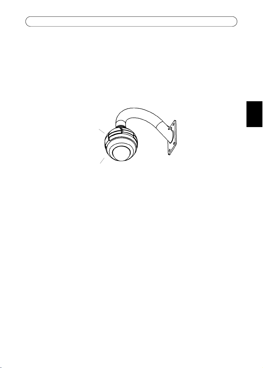
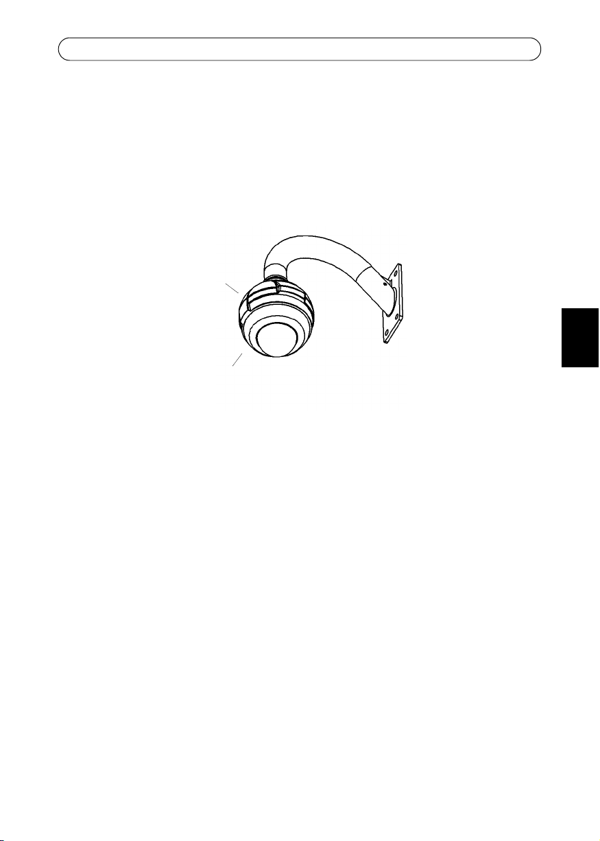
AXIS 216FD/216FD-V/216MFD/216MFD-V Pendant Kit
Wall mount
(not included)
pendant
adapter
AXIS 216FD
(not included)
AXIS 216FD/216FD-V/216MFD/216MFD-V Pendant Kit
This installation guide provides instructions for installing the Pendant Kit for the AXIS
216FD/216FD-V/216MFD/216MFD-V Fixed Dome Network Camera, in this document
referred to as AXIS 216FD. Please read through the entire guide before proceeding with the
installation.
For instructions on how to install the camera, please refer to the AXIS 216FD/216FD-V/
216MFD/216MFD-V Installation Guide, available from www.axis.com or the AXIS Network
Video CD.
Before you begin
Before you begin, make sure you have the following components:
3
ENGLISH
• Pendant adapter kit
Additional components (not included):
• AXIS 216FD/216FD-V/216MFD/216MFD-V Network Camera
• Wall mount bracket
• Suitable screws/plugs for the wall mount bracket
• Pozidriv screwdriver (to attach the camera unit to the pendant adapter)
Package contents:
• (1) Cast aluminum pendant adapter
• (1) Pendant adapter gasket
• (1) 1.5 inch to 22mm adapter (not available in all pendant kits)
• (2) M4 x 16 Pozidriv screws
• (1) M4 x 20 Pozidriv screw
Package contents:
• (2) Pozidriv screws (not used for pendant adapter)
• (2) Tamper-proof screws
• (1) Screwdriver for tamper-proof screws
Page 4

4
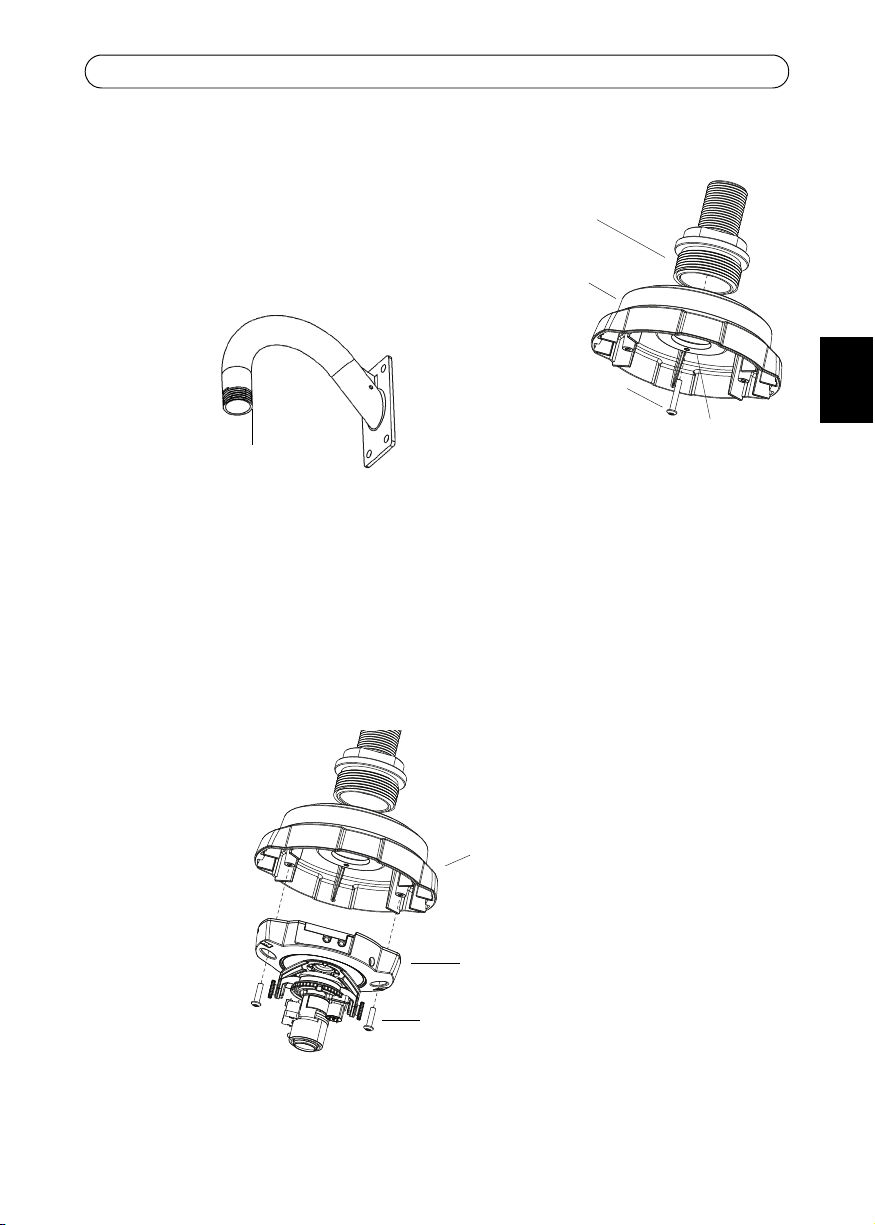
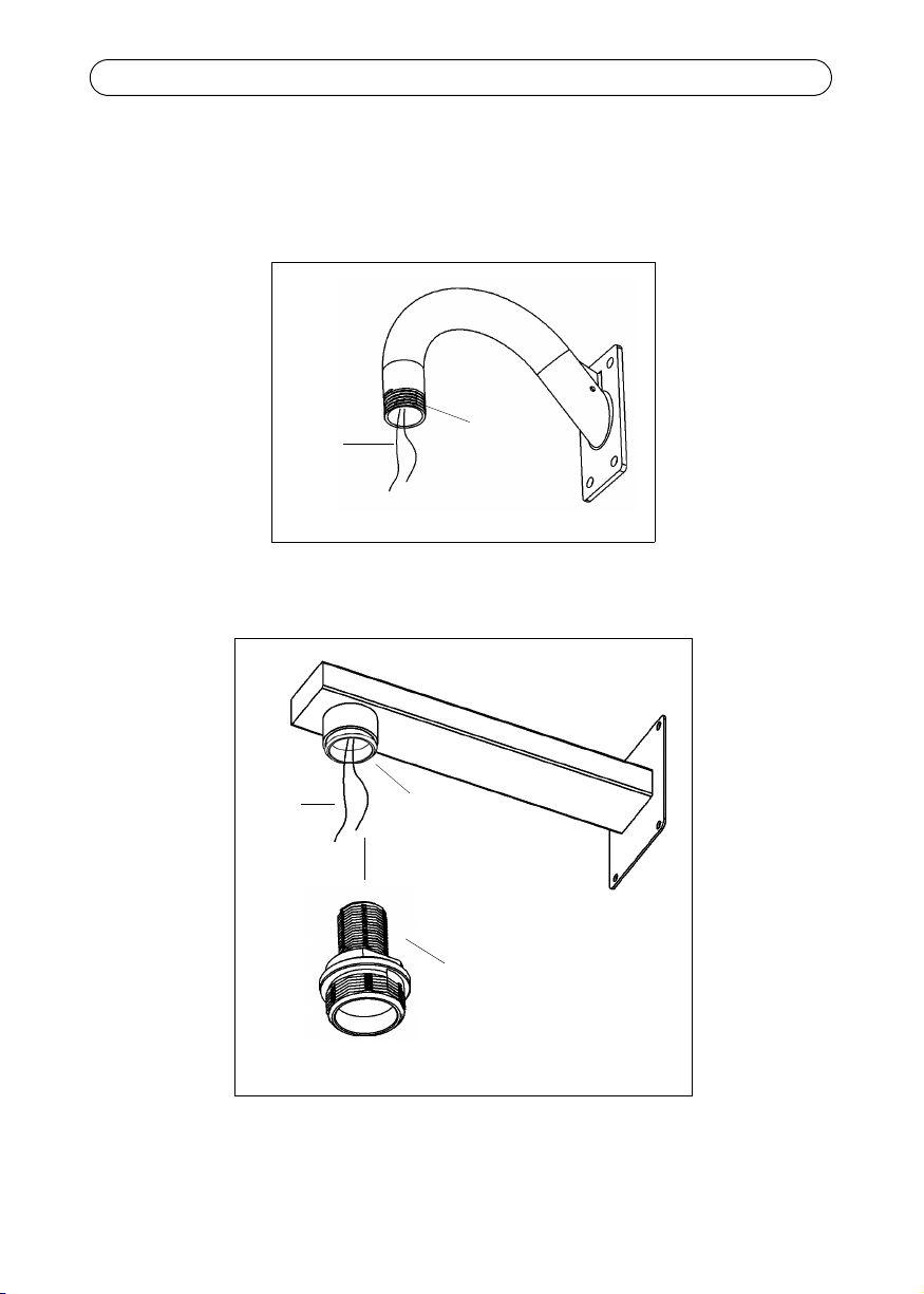
Cables
Wall mount bracket (1.5 inch pipe)
1.5 inch pipe
Cables
1.5 inch-22 mm adapter
Wall mount bracket (1.5 inch to 22 mm adapter)
22 mm pipe
AXIS 216FD/216FD-V/216MFD/216MFD-V Pendant Kit
Install the wall mount bracket
Route the power and network cables (including I/O and audio cables if used) through the
wall mount bracket and allow to extend as shown. Install the wall mount bracket securely,
in the desired position.
Page 5
AXIS 216FD/216FD-V/216MFD/216MFD-V Pendant Kit
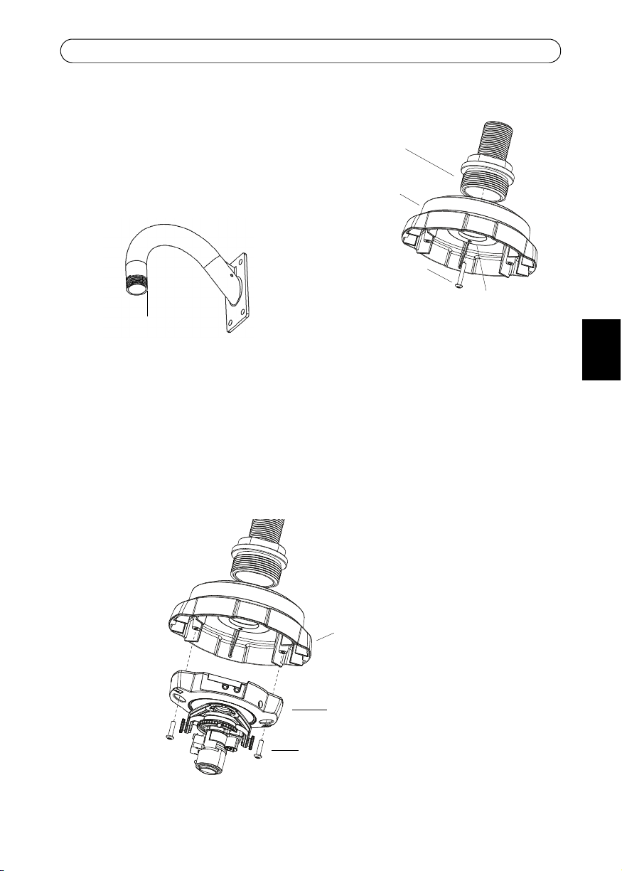
M4x20 screw
Locking screw hole
pendant
adapter
Wall mount bracket
(supplied)
Recommended
locking screw position
M4x16 screws (supplied)
pendant adapter
Camera unit
Attach the pendant adapter
1. Attach the pendant adapter to the wall mount
bracket.
2. Lock the pendant adapter in the correct position on
the wall mount bracket, using the supplied M4x20
screw in the locking screw hole.
Attach the camera unit
Note:
Before installing the camera, make a note of the serial number (S/N) which is located on the
product label on the base of the camera unit. The serial number is used in the installation.
Attach the camera unit to the pendant adapter using the supplied M4x16 screws.
5
ENGLISH
Page 6
6
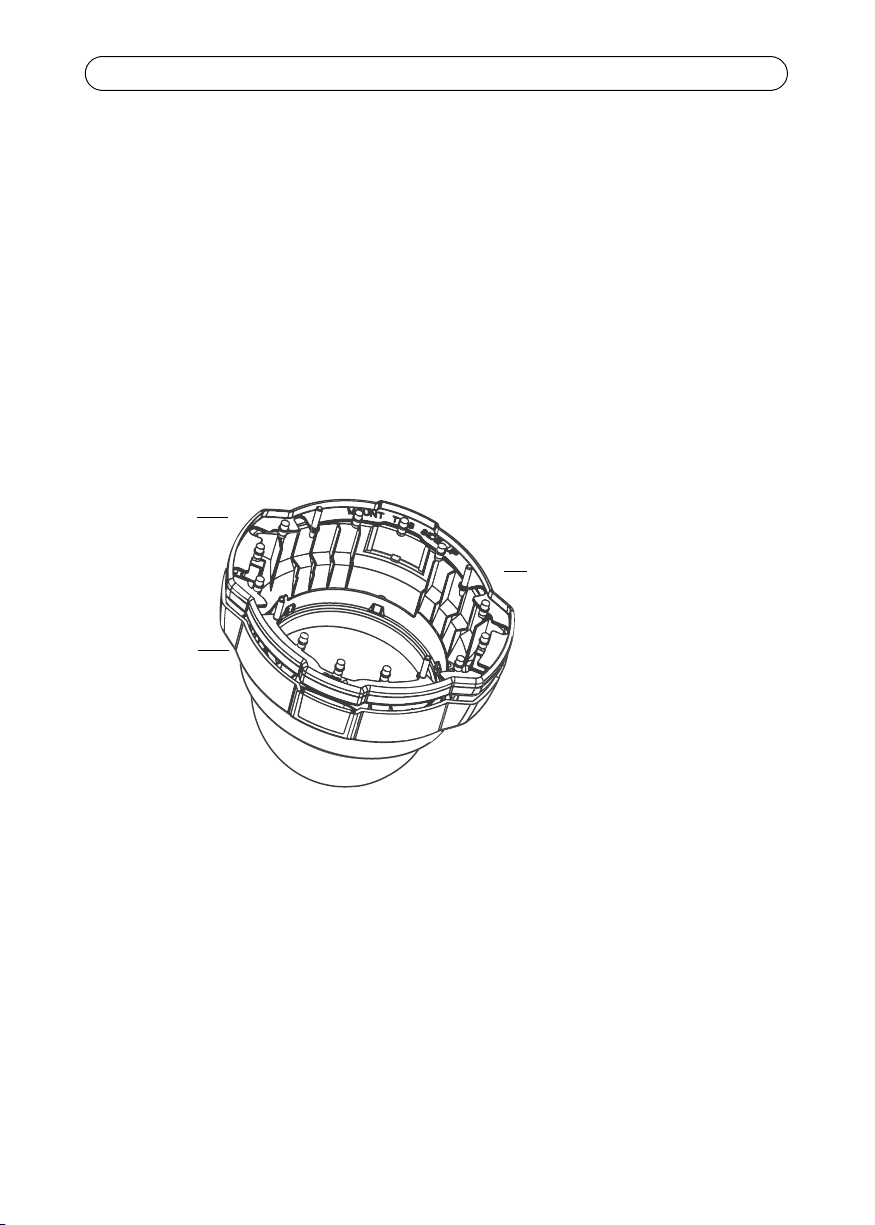
AXIS 216FD
dome casing
Rubber
Make sure that the gasket is
properly fitted with ‘MOUNT
THIS SIDE UP’ visible when
placed on the dome casing.
gasket
AXIS 216FD/216FD-V/216MFD/216MFD-V Pendant Kit
Install the camera
Refer to the AXIS 216FD Installation Guide to:
• connect the cables to the camera unit
• set the IP address
• focus the camera
• make the necessary image adjustments
Note:
The installation guide is available from the Axis web site at www.axis.com or from the AXIS
Network Video CD supplied with the camera.
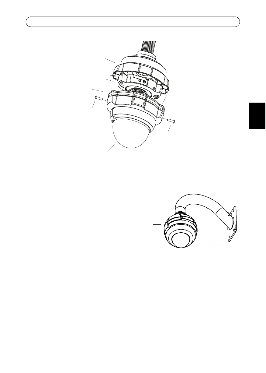
Complete the installation
1. Stretch the rubber gasket round the edge of the dome casing. Align the Axis logotype
on the gasket with the printed logotype on the dome casing.
2. Attach the dome casing and gasket to the pendant adapter.
3. Secure the dome casing using the supplied tamper-proof screws.
Note:
The gasket is not designed to carry the weight of the dome casing, be sure to hold the dome
casing until it is securely held in place by the tamper-proof screws.
Page 7
AXIS 216FD/216FD-V/216MFD/216MFD-V Pendant Kit
Tamper-proof
screw
Pendant adapter
Camera unit
Gasket
Dome
casing
Tamper-proof
screw
Axis logotype
on this side
The installation is now complete.
For more information on the
functionality of the AXIS 216FD,
please refer to the user’s manual or the
online help files.
The AXIS 216FD User’s Manual is
available from the Axis web site at
www.axis.com or from the AXIS
Network Video CD supplied with the
camera.
7
ENGLISH
Page 8

Page 9
AXIS 216FD/216FD-V/216MFD/216MFD-V Kit suspendu
Support mural
(non incluse)
adaptateur
suspendu
AXIS 216FD
(non incluse)
AXIS 216FD/216FD-V/216MFD/216MFD-V Kit suspendu
Ce guide d'installation vous explique comment installer le kit suspendu pour l’AXIS 216FD/
216FD-V/216MFD/216MFD-V caméra réseau à dôme fixe, appelée AXIS 216FD dans ce
document. Lisez attentivement ce guide avant de poursuivre l'installation.
Pour obtenir des instructions sur l'installation de la caméra, reportez-vous au guide
d'installation AXIS 216FD/216FD-V/216MFD/216MFD-V , disponible sur www.axis.com ou
sur le CD du produit vidéo réseau AXIS.
Avant de commencer
Avant de commencer l'installation, vérifiez que vous possédez les composants suivants :
9
FRANCAIS
• Kit d'adaptateur suspendu
Contenu de l'emballage :
• (1) Adaptateur suspendu en aluminium coulé
• (1) Joint d'adaptateur suspendu
• (1) Adaptateur 1,5 pouce à 22mm (non disponible pour tous les kits pendants)
• (2) Vis à empreinte cruciforme M4 x 16
• (1) Vis à empreinte cruciforme M4 x 20
Autres composants (non inclus) :
• AXIS 216FD/216FD-V/216MFD/216MFD-V Caméra réseau
Contenu de l'emballage :
• (2) Vis à tête cruciforme (non utilisées pour l'adaptateur suspendu)
• (2) Vis inviolables
• (1) Tournevis pour vis inviolables
• Support mural
• Vis et chevilles adaptées au support mural
• Tournevis Pozidriv (pour fixer la caméra à l'adaptateur suspendu)
Page 10
10
Câbles
Support mural (tuyau 3,81 cm)
Tuyau 3.81 cm
Câbles
Adaptateur 1,5 pouce - 22 mm
Support mural (adaptateur 1,5 pouce - 22 mm)
Tuyau 22 mm
AXIS 216FD/216FD-V/216MFD/216MFD-V Kit suspendu
Installation du support mural
Faites passer les câbles d'alimentation et réseau (y compris les câbles d'E/S et les câbles
audio si nécessaire) dans le support mural et laissez-les dépasser comme le montre
l'illustration. Fixez solidement le support mural dans la position souhaitée..
Page 11
AXIS 216FD/216FD-V/216MFD/216MFD-V Kit suspendu
Vis M4 x 20
Trou de la vis de verrouillage
adaptateur
suspendu
Support mural
(fournie)
Position
recommandée pour la vis de
verrouillage
Vis M4 x 16 (fournies)
adaptateur suspendu
Caméra
Fixation de l'adaptateur suspendu
1. Fixez l'adaptateur suspendu au support
mural.
2. Fixez correctement l'adaptateur suspendu au
support mural en introduisant la vis M4 x 20
fournie dans le trou de la vis de verrouillage.
Fixation de la caméra
Remarque :
Avant d'installer la caméra, notez le numéro de série (S/N) situé sur l'étiquette du produit au
bas de la caméra. Le numéro de série sera nécessaire pendant l'installation.
Fixez la caméra à l'adaptateur suspendu avec les vis M4 x 16 fournies.
11
FRANCAIS
Page 12

12
Joint en
AXIS 216FD
Boîtier du dôme
Remarque:
Assurez vous que le joint
est correctement posé et que
l’indication « MOUNT THIS SIDE UP »
est visible une fois qu
'il est placé
sur le boîtier du dôme.
caoutchouc
AXIS 216FD/216FD-V/216MFD/216MFD-V Kit suspendu
Installation de la caméra
Consultez le guide d'installation AXIS 216FD afin de :
• connecter les câbles à la caméra ;
• définir l'adresse IP ;
• faire la mise au point de la caméra ;
• procéder aux réglages nécessaires de l'image.
Remarque :
Le guide d'installation de la caméra est disponible sur le site Web d'Axis (www.axis.com) ou
sur le CD du produit vidéo réseau Axis fourni avec la caméra.
Fin de l'installation
1. Étirez le joint en caoutchouc autour du bord du boîtier du dôme. Alignez le logo Axis
du joint sur le logo situé sur le boîtier du dôme.
2. Fixez le boîtier du dôme et le joint à l'adaptateur suspendu.
3. Fixez le boîtier du dôme avec les vis inviolables fournies.
Remarque :
Le joint n'est pas conçu pour supporter le poids du boîtier du dôme. Maintenez-le jusqu'à ce
qu'il soit complètement fixé par les vis inviolables.
Page 13

L'installation est terminée.
Vis
de mise au point
Adaptateur suspendu
Caméra
Joint
Dôme
boîtier
Vis
de mise au point
Logo Axis
de ce côté
Pour plus d'informations sur les
fonctionnalités de l'AXIS 216FD,
consultez le manuel de l'utilisateur ou
les fichiers d'aide en ligne.
Le manuel de l'utilisateur de l'AXIS
216FD est disponible sur le site Web
d'Axis (www.axis.com) ou sur le CD du
produit vidéo réseau Axis fourni avec
la caméra.
AXIS 216FD/216FD-V/216MFD/216MFD-V Kit suspendu
13
FRANCAIS
Page 14

Page 15

AXIS 216FD/216FD-V/216MFD/216MFD-V Aufhängungsset
Wandhalterung
(nicht enthalten)
Aufhängungsadapter
AXIS 216FD
(nicht enthalten)
AXIS 216FD/216FD-V/216MFD/216MFD-V Aufhängungsset
Diese Anleitung beschreibt die Montage des Aufhängungssets für die AXIS 216FD/ 216FD-V/
216MFD/216MFD-V Netzwerk-Kuppelkamera, die in diesem Handbuch weiterhin
zusammenfassend als AXIS 216FD bezeichnet wird. Lesen Sie vor der Montage das gesamte
Handbuch sorgfältig durch.
Anweisungen zur Installation der Kamera finden Sie im Installationshandbuch für die AXIS
216FD/216FD-V/216MFD/216MFD-V, auf der Website www.axis.com oder auf der CD für
Axis-Netzwerkvideoprodukte.
Vorbereitungen
Überprüfen Sie vor der Montage, ob die folgenden Bauteile vorhanden sind:
15
DEUTSCH
• Aufhängungsset
Lieferumfang:
• (1) Aluminium-Aufhängungsadapter
• (1) Dichtungsring für den Aufhängungsadapter
• (1) 5-Zoll auf 22mm-Adapter (nicht in allen Pendant kits enthalten)
• (2) Pozidriv-Schrauben M4x16
• (1) Pozidriv-Schraube M4x20
Zusätzliche Komponenten (nicht enthalten):
• AXIS 216FD/216FD-V/216MFD/216MFD-VNetzwerkkamera
Lieferumfang:
• (2) Pozidriv-Schrauben (nicht für Aufhängungsadapter)
• (2) manipulationssichere Schrauben
• (1) Schraubendreher für manipulationssichere Schrauben
• Wandhalterung
• Passende Schrauben und Dübel für die Wandhalterung
• Pozidriv-Schraubendreher (zur Befestigung der Kamera am Aufhängungsadapter)
Page 16

16
Kabel
Wandhalterung (für 1,5 Zoll-Rohr)
Rohr (1,5 Zoll)
Kabel
Adapter 1,5 Zoll auf 22 mm
Wandhalterung (für Adapter 1,5 Zoll auf 22 mm)
Rohr (22 mm)
AXIS 216FD/216FD-V/216MFD/216MFD-V Aufhängungsset
Wandhalterung montieren
Ziehen Sie Strom- und Netzwerkkabel (ggf. auch E/A- und Audiokabel) durch die
Wandhalterung, so dass diese wie abgebildet aus der Wandhalterung herausragen. Befestigen
Sie die Wandhalterung in der gewünschten Position..
Page 17

AXIS 216FD/216FD-V/216MFD/216MFD-V Aufhängungsset
M4x20-Schraube
Loch für die Feststell-
Aufhängungsadapter
Wandhalterung
(beiliegend)
schraube
Empfohlene
Position für die Feststellschraube
M4x16-Schrauben (beiliegend)
Aufhängungsadapter
Kamera
Aufhängungsadapter befestigen
1. Befestigen Sie den Aufhängungsadapter an der
Wandhalterung.
2. Arretieren Sie den Aufhängungsadapter in der
gewünschten Position an der Wandhalterung,
indem Sie die beiliegende M4x20-Schraube in
das Loch für die Feststellschraube einschrauben.
17
Kamera anschließen
Hinweis:
Notieren Sie sich vor der Installation die Seriennummer (S/N) der Kamera, die sich auf dem
Produktaufkleber an der Kameraunterseite befindet. Die Seriennummer wird für die
Installation benötigt.
Befestigen Sie die Kamera mit Hilfe der beiliegenden M4x16-Schrauben am
Aufhängungsadapter.
DEUTSCH
Page 18

18
Stellen Sie sicher, dass der Dichtungsring
ordnungsgemäß angebracht ist, so dass die
Aufschrift „MOUNT THIS SIDE UP“ bei der
Montage der Kuppelhaube sichtbar ist.
Hinweis:
Gummidichtungsring
AXIS 216FD
Kuppelhaube
AXIS 216FD/216FD-V/216MFD/216MFD-V Aufhängungsset
Kamera installieren
In der Installationsanleitung für die AXIS 216FD finden Sie Anweisungen zu folgenden
Schritten:
• Anschließen der Kabel an die Kamera
• Festlegen der IP-Adresse
• Einstellen der Bildschärfe der Kamera
• Anpassen der notwendigen Bildeinstellungen
Hinweis:
Das Installationshandbuch ist auf der Axis-Website unter http://www.axis.com erhältlich
und befindet sich auch auf der mitgelieferten CD für Axis-Netzwerkvideoprodukte.
Installation abschließen
1. Ziehen Sie den Gummidichtungsring über den Rand der Kuppelhaube. Richten Sie das
Axis-Logo auf dem Dichtungsring am Logo-Aufdruck der Kuppelhaube aus.
2. Befestigen Sie die Kuppelhaube und den Dichtungsring am Aufhängungsadapter.
3. Verwenden Sie zur Befestigung der Kuppelhaube die beiliegenden
manipulationssicheren Schrauben.
Hinweis:
Der Dichtungsring ist nicht dazu ausgelegt das Gewicht der Kuppelhaube allein zu tragen.
Halten Sie die Kuppelhaube daher gut fest, bis sie mit Hilfe der manipulationssicheren
Schrauben sicher befestigt wurde.
Page 19

AXIS 216FD/216FD-V/216MFD/216MFD-V Aufhängungsset
Manipulationssichere
Schraube
Aufhängungsadapter
Kamera
Dichtungsring
Kuppelhaube
Manipulations-
Schraube
sichere
Axis-Logo auf
dieser Seite
Die Installation ist damit abgeschlossen.
Weitere Informationen zu den
Funktionen der AXIS 216FD finden Sie
in der Bedienungsanleitung sowie in
den Online-Hilfedateien.
Das Installationshandbuch für die AXIS
216FD ist auf der Axis-Website unter
http://www.axis.com erhältlich und
befindet sich auch auf der
mitgelieferten CD für AxisNetzwerkvideoprodukte.
19
DEUTSCH
Page 20

Page 21

AXIS 216FD/216FD-V/216MFD/216MFD-V Kit Di Sospensione
Montaggio a parete
(non incluso)
Adattatore per
sospensione
AXIS 216FD
(non incluso)
AXIS 216FD/216FD-V/216MFD/216MFD-V Kit Di Sospensione
Nel presente documento vengono fornite le istruzioni per l'installazione dell’adattore a
sospensione per AXIS 216FD/216FD-V/216MFD/216MFD-V. Leggere l'intero contenuto del
documento prima di procedere con l'installazione.
Per istruzioni sulle modalità di installazione della videocamera, fare riferimento alla Guida
D’ installazione di AXIS 216FD/216FD-V/216MFD/216MFD-V , disponibile sul sito Web
www.axis.com o nel CD relativo ai sistemi video in rete di AXIS.
Operazioni preliminari
21
Prima di iniziare, assicurarsi di disporre dei seguenti componenti:
• Kit per l’adattatore a sospensione
Contenuto della confezione:
• (1) Adattatore a sospensione in alluminio pressofuso
• (1) Guarnizione per l’adattatore a sospensione
• (1) Adattatore da 1,5 pollici a 22 mm (non disponibile in ogni kit di sospensione)
• (2) Viti Pozidriv M4 x 16
• (1) Viti Pozidriv M4 x 20
Componenti aggiuntivi (non inclusi):
• Videocamera di rete AXIS 216FD/216FD-V/216MFD/216MFD-V
Contenuto della confezione:
• (2) Viti Pozidriv (non utilizzate per l'adattatore a sospensione)
• (2) Viti antimanomissione
• (1) Cacciavite per viti antimanomissione
• Staffa per montaggio a parete
• Viti/tasselli adatti alla staffa per montaggio a parete
• Cacciavite Pozidriv (per collegare la videocamera all'adattatore a sospensione)
ITALIANO
Page 22

22
Cavi
Staffa per montaggio a parete (tubo
Tubo da 1,5
pollici
da 1,5 pollici)
Cavi
Adattatore da 1,5 pollici a 22 mm
Staffa per montaggio a parete (adattatore da 1,5 pollici
Tubo da 22 mm
a 22 mm)
AXIS 216FD/216FD-V/216MFD/216MFD-V Kit Di Sospensione
Installazione della staffa per montaggio a parete
Passare i cavi di alimentazione e di rete (inclusi i cavi I/O e audio, se utilizzati) attraverso la
staffa per montaggio a parete come mostrato in figura. Installare saldamente la staffa nella
posizione desiderata..
Page 23

AXIS 216FD/216FD-V/216MFD/216MFD-V Kit Di Sospensione
Vite M4x20
Foro per la vite di fissaggio
Adattatore a
sospensione
Staffa per montaggio a
(in dotazione)
parete
Posizione
consigliata per la vite di fissaggio
Viti M4x16 (in dotazione)
Adattatore a sospensione
Videocamera
Collegamento dell'adattatore a sospensione
1. Collegare l'adattatore a sospensione alla staffa
per montaggio a parete.
2. Fissare l'adattatore a sospensione in posizione
corretta sulla staffa assicurando la vite M4x20
in dotazione nell'apposito foro di fissaggio.
Collegamento dell'unità videocamera
Nota:
Prima di installare la videocamera, prendere nota del numero di serie (S/N) riportato
sull'etichetta del prodotto situata sulla base dell'unità. Il numero di serie viene utilizzato
durante l'installazione.
Collegare la videocamera all'adattatore a sospensione mediante le viti M4x16 in dotazione.
23
ITALIANO
Page 24

24
Guarnizione in
gomma
AXIS 216FD
cupola
Verificare che la guarnizione sia collocata
"MOUNT THIS SIDE UP
" sia visibile
in posizione corretta e che la scritta
una volta collocata la guarnizione sulla
cupola.
AXIS 216FD/216FD-V/216MFD/216MFD-V Kit Di Sospensione
Installazione della videocamera
Fare riferimento alla Guida d'installazione di AXIS 216FD per le seguenti operazioni:
• collegamento dei cavi alla videocamera
• impostazione dell'indirizzo IP
• messa a fuoco della videocamera
• Regolazioni sull'immagine
Nota:
La Guida d'installazione è disponibile sul sito web di Axis all’indirizzo www.axis.com oppure
nel CD relativo ai sistemi video in rete di Axis, fornito con la videocamera.
Completamento dell'installazione
1. Allargare la guarnizione in gomma attorno al bordo della cupola. Allineare il logotipo
Axis sulla guarnizione con il logotipo stampato sulla cupola.
2. Collegare la cupola e la guarnizione all'adattatore a sospensione.
3. Fissare la cupola utilizzando le viti antimanomissione in dotazione.
Page 25

AXIS 216FD/216FD-V/216MFD/216MFD-V Kit Di Sospensione
Vite
antimanomissione
Adattatore a sospensione
Videocamera
Guarnizione
Cupola
Vite
antimanomissione
Logotipo Axis
da questo lato
Nota:
La guarnizione non è progettata per sostenere il peso della cupola. È necessario sorreggere
la cupola finché non è stata fissata saldamente mediante le viti antimanomissione.
L'installazione è stata completata.
Per ulteriori informazioni sulle
modalità di funzionamento di AXIS
216FD, fare riferimento al Manuale
dell'utente e alla Guida online.
Il Manuale dell'utente di AXIS 216FD è
disponibile sul sito Web di Axis
all’indirizzo www.axis.com oppure nel
CD relativo ai sistemi video in rete di
Axis, fornito con la videocamera.
25
ITALIANO
Page 26

Page 27

Kit colgante para AXIS 216FD/216FD-V/216MFD/216MFD-V
Soporte de pared
(no incluido)
adaptador
colgante
AXIS 216FD
(no incluido)
Kit colgante para AXIS 216FD/216FD-V/216MFD/216MFD-V
Esta guía de instalación incluye las instrucciones de instalación del kit colgante para la
Cámara de red con burbuja fija AXIS 216FD/216FD-V/216MFD/216MFD-V, denominada
AXIS 216FD en este documento. Por favor lea la guía completa, antes de comenzar la
instalación.
Para obtener instrucciones sobre cómo instalar la cámara, consulte la Guía de instalación de
la AXIS 216FD/216FD-V/216MFD/216MFD-V disponible en www.axis.com o en el CD sobre
el producto de vídeo de red de Axis.
Antes de comenzar
27
Antes de comenzar, asegúrese de que tiene los componentes siguientes:
• Kit de adaptador colgante
Contenido del paquete:
• (1) Adaptador colgante de aluminio fundido
• (1) Junta del adaptador colgante
• (1) Adaptador de 1,5 pulgadas a 22mm (no disponible en todos los kits colgantes)
• (2) Tornillos pozidriv M4 x 16
• (1) Tornillo pozidriv M4 x 20
Componentes adicionales (no incluidos):
• AXIS 216FD/216FD-V/216MFD/216MFD-V Cámara de red
Contenido del paquete:
• (2) Tornillos pozidriv (no se utilizan para el adaptador colgante)
• (2) Tornillos de alta resistencia
• (1) Destornillador para tornillos de alta resistencia
• Soporte de pared
• Tornillos/tapones adecuados para el soporte de pared
• Destornillador pozidriv (para fijar la cámara al adaptador colgante)
ESPAÑOL
Page 28

28
Cables
Soporte de pared con tubo de 38 mm
Tubo de 38 mm
Cables
Adaptador de 38 mm a 22 mm
Soporte de pared (con adaptador de 38 mm a 22 mm)
Tubo de 22 mm
Kit colgante para AXIS 216FD/216FD-V/216MFD/216MFD-V
Instalación del soporte de pared
Pase los cables de alimentación y de red (incluidos los cables de E/S y audio si se utilizan)
través del soporte de pared, de forma que queden extendidos como se muestra en la
ilustración. Instale de forma segura el soporte de pared en la posición deseada..
Page 29

Kit colgante para AXIS 216FD/216FD-V/216MFD/216MFD-V
Tornillo M4 x 20
Orificio del tornillo de bloqueo
adaptador
colgante
Soporte de pared
(incluido)
Posición
recomendada del tornillo de
bloqueo
Tornillos M4 x 16 (incluidos)
adaptador colgante
Unidad de la cámara
Fijación del adaptador colgante
1. Fije el adaptador colgante al soporte de pared.
2. Fije el adaptador colgante al soporte de pared
en la posición correcta y bloquéelo colocando
el tornillo M4 x 20 en el orificio de bloqueo.
Fijación de la cámara
Nota:
Antes de instalar la cámara, anote el número de serie (N/S) que aparece en la etiqueta del
producto situada en la base de la carcasa de la unidad. El número de serie se utiliza durante la
instalación.
Fije la cámara al adaptador colgante utilizando los tornillos M4 x 16 incluidos.
29
ESPAÑOL
Page 30

30
Asegúrese de que la
carcasa está colocada
correctamente con la
frase "MOUNT THIS
SIDE UP" visible al
ponerla en la carcasa de
la burbuja.
Nota:
Carcasa de la burbuja
de la AXIS 216FD
Junta de goma
Kit colgante para AXIS 216FD/216FD-V/216MFD/216MFD-V
Instalación de la cámara
Consulte la Guía de instalación de la AXIS 216FD para:
• conectar los cables a la unidad de la cámara
• configurar la dirección IP
• ajustar el enfoque de la cámara
• hacer los ajustes de imagen necesarios
Nota:
Puede acceder a la guía de instalación en la página Web de Axis www.axis.com, o bien en el
CD sobre el producto de vídeo de red de Axis incluido con la cámara.
Finalización de la instalación
1. Coloque la junta de goma alrededor del borde de la carcasa de la burbuja. Alinee el
logotipo de Axis de la junta con el logotipo impreso de la carcasa de la burbuja.
2. Fije la carcasa de la burbuja y la junta al adaptador colgante.
3. Fije la carcasa de la burbuja utilizando los tornillos de alta resistencia incluidos.
Page 31

Kit colgante para AXIS 216FD/216FD-V/216MFD/216MFD-V
Tornillo de
alta resistencia
Adaptador colgante
Unidad de la
Junta
Carcasa de
la burbuja
Tornillo de
alta resistencia
cámara
Logotipo de Axis
en este lado
Nota:
La junta no está diseñada para soportar el peso de la carcasa de la burbuja. Sujete la carcasa
de la burbuja hasta que esté fijada con los tornillos de alta resistencia.
31
La instalación ha finalizado.
Para obtener más información sobre la
funcionalidad de la AXIS 216FD,
consulte el manual del usuario o los
archivos de ayuda en línea.
Puede acceder al manual del usuario de
la AXIS 216FD en la página Web de
Axis www.axis.com, o bien en el CD
sobre el producto de vídeo de red de
Axis incluido con la cámara.
ESPAÑOL
Page 32

Page 33

Page 34

Installation Guide Ver.1.1
AXIS 216FD Pendant Kit Printed: July 2011
© Axis Communications AB, 2009-2011 Part No. 43753
 Loading...