


AVISTART 4000
AviStart 4000 Installation - Front Cover


Table of Contents
Important Information ........................... 2
Recommended Installation Tools..................... 2
Recommended Procedures ....................... 2
Main Wiring Diagram .......................... 3
16 Pin Connector............................ 4
6 Pin Connector............................. 4
Installation Procedures...........................5
Control Unit............................... 5
RangeMaster™ Super Heterodyne Receiver Module ........... 5
Wireloom ................................ 5
LED Indicator..............................6
Valet Switch...............................6
Brake Lights (Mandatory) ........................6
Parking Lights..............................7
Reverse Light...............................7
Interior Light Illumination Output ....................7
Trunk Release .............................. 8
Remote Start Armed Signal (-) Output .................. 8
Remote Panic Capability......................... 8
Factory Alarm Disarm (-) Output..................... 8
Ignition Switch Connections....................... 9
Remote Engine Start Neutral Safety Switch Bulletin .......... 10
Door Lock/Unlock ........................... 13
Door Lock Diagrams..........................13
Tach Wire (RPM Monitoring)...................... 16
Hood Switch (Mandatory) ....................... 16
Power and Ground Connections .................... 17
Mandatory RPM Programming .....................17
Programmable Features.......................... 18
Programming Table for System Features ................ 19
Programming Table for Remote Controls................ 20
1
AviStart 4000 Installation Manual - 8/98 Rev. B

Important Information
Recommended Installation Tools
Voltmeter
Wire Strippers
Electrical Drill & Bits
Phillips Screwdriver
Convoluted Tubing *
Solder Gun *
Wire Crimpers
Shrink Tube or Electrical Tape
* Optional
Recommended Procedures
1. Test all circuits with a voltmeter.
2. Make all wiring connections with the supplied solderless crimp
connectors. DO NOT twist wires or use scotch-lok connectors.
3.
Route the small and large RED, RED/WHITE and BLACK wires from the
control unit directly to the battery.
4. Keep extensions as short as possible. Use same gauge wires for short
extensions and larger gauge wires for longer extensions.
5. Before installing, discuss the placement of the LED indicator and valet
switch with the vehicle owner.
6. DO NOT disconnect the battery cables. Make all connections by
removing the bolts from the cable clamps without detaching the clamp.
7. Turn off dome light or remove dome light fuse to prevent battery drain.
This device complies with Part 15 of the FCC rules. Any changes or
modifications made to the system without the express approval of Avital
Technologies, Inc. could void the user’s authority to operate this
equipment.
2
AviStart 4000 Installation Manual - 8/98 Rev. B
3
AviStart 4000 Installation Manual - 8/98 Rev. B
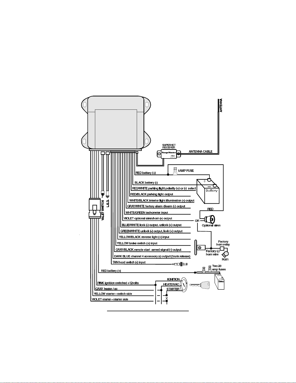
Main Wiring Diagram

16 Pin Connector
Pin Number Wire Color Description
1
GRAY/BLACK
Remote Start Armed Signal (-) Output
2
GRAY/WHITE
Factory Alarm Disarm (-) Output
3 DARK BLUE Channel 4 (-) Output (Trunk Release)
4
WHITE/BLACK
Dome Light Supervision (-) Output
5
YELLOW
Brake Switch (+) Input
6 YELLOW/BLACK Reverse Light (+) Input
7
TAN
Hood Switch (-) Input
8
BLANK
Not Used
9 RED/WHITE Parking Light Polarity Input, (+) or (-) Select
10
RED/BLACK
Parking Light Output
11
RED
Battery (+)
12 VIOLET Siren/Horn Output
13
BLUE/WHITE
Lock (-) or Unlock (+) Output
14
GREEN/WHITE
Unlock (-) or (+) Lock Output
15 BLACK Battery (-)
16
WHITE/LIGHT GREEN
Tachometer Input
6 Pin Connector
Pin Number Wire Color Description
1
YELLOW
Starter Interrupt Switch Side
2
GRAY
Heater/AC Output
3 VIOLET Starter Interrupt Starter Side
4
PINK
Ignition Output
5
RED
Battery (+)
6 BLANK Not Used
4
AviStart 4000 Installation Manual - 8/98 Rev. B

Installation Procedures
Control Unit
1. Select a location under the dash that will allow you to use the tie wraps to
securely fasten the control unit.
2. Mount the control unit as high as possible to ensure maximum security.
3. Do not mount the control unit near moving parts.
4. Avoid areas that are in the direct path of air blowing from the vents.
5. Route wires from this point, leaving slack for ease of service.
RangeMaster™ Super Heterodyne Receiver Module
1.
Plug the receiver module WHITE connector into the control unit WHITE
plug.
2. Use tie wraps to fasten the receiver module as far from the control unit as
possible.
3. Route the antenna cable up through the driver side windshield pillar,
behind the headliner and behind the rear view mirror.
4. Use the small mounting tabs to connect the antenna to the windshield,
behind the rear view mirror approximately 2" below the top of the
windshield.
Wireloom
1. Plug the wireloom securely into the control unit.
2. Route wires from the control module directly to each connection point.
3.
Separate the small and large RED , RED/WHITE , BLACK, TAN, and
WHITE/GREEN wires.
4. Sleeve these wires with vinyl tubing or electrical tape and route them
through an existing rubber grommet into the engine compartment.
5. If an existing grommet is not available, drill a hole and install a snap
grommet.
5
AviStart 4000 Installation Manual - 8/98 Rev. B

LED Indicator
1. Discuss placement with the owner.
2. Choose a location that is visible from both sides of the vehicle.
3. Drill a ¼" hole.
4. Route the LED wires through the hole and press LED into place.
5. Route the LED wires to the control unit.
6.
Plug the RED LED connector into the control unit RED plug.
Valet Switch
1. Discuss placement with the owner.
2. Choose a location for the valet switch that is hidden, but convenient for
the owner to access.
3. Drill a ¼" hole and mount the switch.
4. Route the valet switch wires to the control unit.
5.
Plug the valet switch WHITE connector into the control unit WHITE plug.
Brake Lights (Mandatory)
I
CAUTION : As a safety feature, the unit monitors the brake light to
prevent an unauthorized driver from driving the car and to switch to
normal engine operating condition. For this reason, the YELLOW
brake light input wire must be connected and the brake light must be
in working condition or the remote start will not operate properly.
1. Turn the ignition key to the "ON" position, then press the brake pedal and
make sure the brake light illuminates.
2. Use a voltmeter to find the one wire at the brake light switch (usually
located on the upper brake pedal arm) that shows +12 volts when you
press the brake pedal and 0 volts when the brake pedal is not pressed.
3.
Connect the YELLOW wire to the vehicle brake light switch wire.
6
AviStart 4000 Installation Manual - 8/98 Rev. B
 Loading...