


Avital
Model 4103
Installation Guide
NOTE: This product is intended for installation by a professional installer only! Any attempt to install this product by any person other than a trained professional may result in severe damage to a vehicle’s electrical system and components.
© 2008 Directed Electronics, Vista, CA
N4103L 2008-07

Bitwriter®, Code Hopping™, Doubleguard®, ESP™, FailSafe®, Ghost Switch™, Learn Routine™, Nite-Lite®, Nuisance Prevention® Circuitry, Revenger®, Silent Mode™, Soft Chirp®, Stinger®, Valet®, Vehicle Recovery System®, VRS®, and Warn Away® are all Trademarks or Registered Trademarks of Directed Electronics.
The Bitwriter® (p/n 998U) requires chip version 2.5 or newer to program this unit.
Bitwriters with a date code of 6a or older require an IC upgrade (p/n 998M). Some bitwriters with a date code of 6B do not require the IC upgrade, refer to tech tip # 1112 for more information. Bitwriter 2 compatible.

Contents |
|
Government Regulations..................................................................................... |
5 |
Warning! safety first........................................................................................... |
6 |
What is included............................................................................................... |
8 |
Installation points to remember............................................................................ |
9 |
Virtual tach............................................................................................. |
10 |
D2D...................................................................................................... |
10 |
Component locations and finding wires.............................................................. |
11 |
Making your wiring connections........................................................................ |
11 |
Primary harness (H1) wiring diagram........................................................ |
12 |
4-pin satellite harness diagram.................................................................. |
12 |
Heavy gauge relay wiring diagram........................................................... |
12 |
Door lock harness, 3-pin connector............................................................ |
13 |
Remote start harness (H2) wiring diagram.................................................. |
13 |
Primary harness (H1), 9-pin connector................................................................ |
14 |
Heavy gauge relay interface............................................................................. |
20 |
Remote start harness (H2), 5-pin connector......................................................... |
21 |
Neutral safety switch interface........................................................................... |
24 |
D2D and programmer interface......................................................................... |
25 |
Programming jumpers...................................................................................... |
26 |
Light flash (+)/(-)...................................................................................... |
26 |
Plug-in program switch..................................................................................... |
27 |
Tach learning.................................................................................................. |
27 |
Virtual tach............................................................................................. |
27 |
To learn the tach signal............................................................................ |
28 |
Tach threshold on/off............................................................................... |
28 |
Remote control learn routine.............................................................................. |
29 |
Remote Configuration.............................................................................. |
31 |
Operating settings learn routine......................................................................... |
32 |
Features menu................................................................................................. |
34 |
Menu 1.................................................................................................. |
34 |
Menu 2.................................................................................................. |
35 |
Feature descriptions......................................................................................... |
36 |
Menu 1.................................................................................................. |
36 |
Menu 2.................................................................................................. |
38 |
Shutdown diagnostics....................................................................................... |
42 |
Safety check................................................................................................... |
43 |
Troubleshooting............................................................................................... |
45 |
Wiring quick reference guide............................................................................ |
48 |
Wiring quick reference guide continued............................................................. |
49 |

Government Regulations
This device complies with Part 15 of FCC rules. Operation is subject to the following two conditions: (1) This device may not cause harmful interference, and
(2) This device must accept any interference received, including interference that may cause undesirable operation.
This equipment has been tested and found to comply with the limits for a class B digital device, pursuant to Part 15 of the FCC Rules. These limits are designed to provide reasonable protection against harmful interference in a residential installation. This equipment generates and can radiate radio frequency energy and, if not installed and used in accordance with the instruction manual, may cause harmful interference to radio communications. However, there is no guarantee that interference will not occur in a particular installation. If this equipment does cause harmful interference to radio or television, which can be determined by turning the equipment OFF and ON, the user is encouraged to try to correct the interference by one or more of the following measures:
•Reorient or relocate the receiving antenna.
•Increase the separation between the equipment and receiver.
•Connect the equipment into an outlet on a circuit different from that to which the receiver is connected.
•Consult the dealer or an experienced radio / TV technician for help.
This device complies with the Industry Canada Radio Standards Specification RSS 210. Its use is authorized only on a no-interference, no-protection basis; in other words, this device must not be used if it is determined that it causes harmful interference to services authorized by IC. In addition, the user of this device must accept any radio interference that may be received, even if this interference could affect the operation of the device.
Warning:
Changes or modifications not expressly approved by the party responsible for compliance could void the user’s authority to operate this device.
© 2008 Directed Electronics. All rights reserved. |
5 |

 Warning! safety first
The following safety warnings must be observed at all times:
•Due to the complexity of this system, installation of this product must only be performed by an authorized Directed Electronics dealer.
•When properly installed, this system can start the vehicle via a command signal from the remote control. Therefore, never operate the system in an area that does not have adequate ventilation.
The following precautions are the sole responsibility of the user; however, authorized Directed Electronics dealers should:
•Never use a test light or logic probe when installing this unit. Always use a multimeter.
•Never operate the system in an enclosed or partially enclosed area without ventilation (such as a garage).
•When parking in an enclosed or partially enclosed area or when having the vehicle serviced, the remote start system must be disabled using the installed toggle switch. It is the user’s sole responsibility to properly handle and keep out of reach from children all remote controls to assure that the system does not unintentionally remote start the vehicle.
•USER MUST INSTALL A CARBON MONOXIDE DETECTOR IN OR ABOUT THE LIVING AREA ADJACENT TO THE VEHICLE. ALL DOORS LEADING FROM ADJACENT LIVING AREAS TO THE ENCLOSED OR PARTIALLY ENCLOSED VEHICLE STORAGE AREA MUST REMAIN CLOSED AT ALL TIMES.
Use of this product in a manner contrary to its intended mode of operation may result in property damage, personal injury, or death. Except when performing the Safety Check outlined in this installation guide, (1) Never remotely start the vehicle with the vehicle in gear, and (2) Never remotely start the vehicle with the keys in the ignition. The user is responsible for having the neutral safety feature of the vehicle periodically checked, wherein the vehicle must not remotely start while the car is in gear. This testing should be performed by an authorized Directed Electronics dealer in accordance with the Safety Check outlined in this product installation guide. If the vehicle starts in gear, cease remote start opera-
6 |
© 2008 Directed Electronics. All rights reserved. |
tion immediately and consult with the user to fix the problem immediately.
After the remote start module has been installed, test the remote start module in accordance with the Safety Check outlined in this installation guide. If the vehicle starts when performing the Neutral Safety Shutdown Circuit test, the remote start unit has not been properly installed. The remote start module must be removed or properly reinstalled so that the vehicle does not start in gear. All installations must be performed by an authorized Directed Electronics dealer.
OPERATION OF THE REMOTE START MODULE IF THE VEHICLE STARTS IN GEAR IS CONTRARY TO ITS INTENDED MODE OF OPERATION. OPERATING THE REMOTE START SYSTEM UNDER THESE CONDITIONS MAY RESULT IN PROPERTY DAMAGE OR PERSONAL INJURY. IMMEDIATELY CEASE THE USE OF THE UNIT AND REPAIR OR DISCONNECT THE INSTALLED REMOTE START MODULE. DIRECTED ELECTRONICS WILL NOT BE HELD RESPONSIBLE OR PAY FOR INSTALLATION OR REINSTALLATION COSTS.
© 2008 Directed Electronics. All rights reserved. |
7 |

What is included
•The control module (see diagram)
•HX antenna receiver
•Two remote transmitters
•A push-button Valet switch
•A hood pinswitch
•A shut-down toggle switch
|
Red 4 pin D2D/Bitwriter port |
8 |
© 2008 Directed Electronics. All rights reserved. |

Installation points to remember
Important: This product is designed for fuel-injected, automatic transmission vehicles only. Installing it in a standard transmission vehicle is dangerous and is contrary to its intended use.
Before beginning the installation:
•Please read this entire installation guide before beginning the installation. The installation of this remote start system requires interfacing with many of the vehicle’s systems. Many new vehicles use low-voltage or multiplexed systems that can be damaged by low resistance testing devices, such as test lights and logic probes (computer safe test lights). Test all circuits with a high quality digital multi-meter before making connections.
•Do not disconnect the battery if the vehicle has an anti-theft-coded radio. If equipped with an air bag, avoid disconnecting the battery if possible. Many airbag systems will display a diagnostic code through their warning lights after they lose power. Disconnecting the battery requires this code to be erased, which can require a trip to the dealer.
•Remove the dome light fuse. This prevents accidentally draining the battery.
•Roll down a window to avoid being locked out of the vehicle.
•After the installation:
•Test all functions. The “Using Your System” section of the Owner’s Guide is very helpful when testing.
•Complete the vehicle Safety Check outlined in this manual prior to the vehicle reassembly.
© 2008 Directed Electronics. All rights reserved. |
9 |
Virtual tach
Virtual Tach is a new feature for Directed this year. It is the default RPM-sensing method for new remote start systems. Virtual Tach gives the installer the performance of a hardwired tach wire, with the convenience of voltage sensing. It is far superior to any voltage-sense feature you’ve tried before.
Virtual Tach monitors the cranking voltage of the vehicle using a very fast micro-controller and an analog-to-digital converter. The microprocessor “saves” the base voltage as a reference. When Virtual Tach “sees” the slightest uptick in voltage, indicating that the alternator is charging the battery, the starter motor shuts off instantly.
D2D
The system has the ability to interface with an XK module through the D2D port. The advantage to using a D2D interface is that there is less wiring involved in the installation. Check the XK module installation guide to determine which wires are not needed, and which options are available.
Component locations and finding wires
For detailed information on where to locate components, and how
to find the wires you need, please refer to the Direct Tech web site at
www.directechs.com.
Making your wiring connections
Before making your connections, plan how your wires will be routed through the vehicle. For instance, the red 12V constant input and the remote start ignition wires are often routed together to the ignition switch harness. In order to keep the wiring neat and make it harder to find, you may wish to wrap these wires together in electrical tape or conceal them in tubing similar to what the manufacturer used.
There are two acceptable ways of making a wire connection - solder connections and crimp connectors. When properly performed, either type of connection is reliable and trouble-free. Regardless of whether you solder your connections or you use mechanical type crimp-on connections, ensure that all connections are mechanically sound and that they are insulated, especially when connecting data lines in the vehicle.
Cheap electrical tape, especially when poorly applied, is not a reliable insulator. It often falls off in hot weather. Use good quality electrical tape or heat shrink.
•Never twist-and-tape the wires together without soldering.
•Never use “fuse taps”, as they can damage fuse box terminals.
If you use tapping connectors such as T-Taps (not to be confused with Scotch-Locks), avoid using them in higher-current applications (constant 12V, ground, etc.) These connectors are inferior in quality and should be avoided.
© 2008 Directed Electronics. All rights reserved. |
11 |

Primary harness (H1) wiring diagram
H1/1 |
LIGHT GREEN/ |
FACTORY ALARM DISARM |
|
BLACK |
|
|
|
|
H1/2 |
GREEN/WHITE |
FACTORY REARM |
|
|
|
H1/3 |
YELLOW |
(+) IGNITION OUT (TO ALARM) |
|
|
|
H1/4 |
WHITE/BLUE |
(-) ACTIVATION INPUT |
|
|
|
H1/5 |
ORANGE |
(-) GROUND WHEN LOCKED |
|
|
|
H1/6 |
BROWN |
(-) HORN OUTPUT |
|
|
|
H1/7 |
RED/WHITE |
(-) TRUNK RELEASE OUTPUT |
|
|
|
H1/8 |
BLACK |
GROUND |
|
|
|
H1/9 |
WHITE |
(+/-) LIGHT FLASH |
|
|
|
4-pin satellite harness diagram
1 |
BLUE |
STATUS OUTPUT |
|
|
|
2 |
ORANGE |
(-) ACCESSORY OUTPUT |
|
|
|
3 |
PURPLE |
(-) STARTER OUTPUT |
|
|
|
4 |
PINK |
(-) STARTER OUTPUT |
|
|
|
Heavy gauge relay wiring diagram
1 |
PINK |
(+) (30 |
AMP) OUTPUT TO IGNITION CIRCUIT |
|
|
|
|
2 |
PURPLE |
(+) (30 |
AMP) OUTPUT TO STARTER CIRCUIT |
|
|
|
|
3 |
ORANGE |
(+) (30 |
AMP) OUTPUT TO ACCESSORY CIRCUIT |
|
|
|
|
4 |
RED |
(+) (30A) HIGH CURRENT 12 INPUT |
|
|
|
|
|
5 |
PINK/WHITE |
(+) PROGRAMMABLE OUTPUT FOR ACCESSORY OR IGNITION |
|
|
|
|
|
6 |
RED |
(+) (30A) HIGH CURRENT 12V INPUT |
|
|
|
|
|
12 |
© 2008 Directed Electronics. All rights reserved. |

Door lock harness, 3-pin connector
1 |
BLUE |
(-) UNLOCK OUTPUT |
|
|
|
2 |
EMPTY |
NOT USED |
|
|
|
3 |
GREEN |
(-) LOCK OUTPUT |
|
|
|
Remote start harness (H2) wiring diagram
H2/1 |
BLACK/WHITE |
(-) NEUTRAL SAFETY SWITCH INPUT |
|
|
|
H2/2 |
VIOLET/WHITE |
TACHOMETER INPUT WIRE |
|
|
|
H2/3 |
BROWN |
(+) BRAKE SWITCH SHUTDOWN WIRE |
|
|
|
H2/4 |
GRAY |
(-) HOOD PINSWITCH SHUTDOWN WIRE |
|
|
|
H2/5 |
BLUE/WHITE |
(-) 200mA 2ND STATUS/REAR DEFOGGER OUTPUT |
|
|
|
© 2008 Directed Electronics. All rights reserved. |
13 |
Primary harness (H1), 9-pin connector
H1/1 |
LIGHT GREEN/ |
FACTORY ALARM DISARM |
|
BLACK |
|
|
|
|
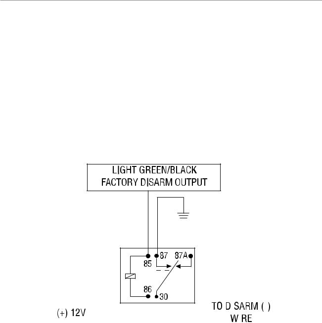
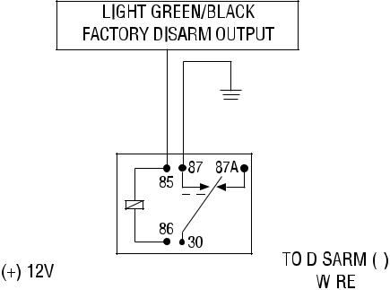
This wire sends a negative pulse every time the remote start is activated or the doors are unlocked. This can be used to pulse the disarm wire of the vehicle’s factory anti-theft device. Use a relay to send a (-) or (+) pulse to the disarm wire as shown in the following diagram
Delay for Negative (-) Disarm Wire
14 |
|
|
|
|
|
|
|
|
|
|
|
|
|
|
|
|
|
|
|
|
|
|
|
|
|
|
|
|
|
|
|
|
|
|
|
|
|
|
|
|
|
|
|
|
|
|
|
|
|
|
|
|
|
|
|
|
|
|
|
|
|
|
|
|
|
|
|
|
|
|
|
|
|
|
|
|
|
|
|
|
|
|
|
|
|
|
|
|
|
|
|
|
|
|
|
|
|
|
|
|
|
|
|
|
|
|
|
|
|
|
|
|
|
|
|
|
|
|
|
|
|
© 2008 Directed Electronics. All rights reserved. |
|||||||
Relay for Positive (+) Disarm Wire
|
|
|
|
|
|
|
|
|
|
|
|
|
|
|
|
|
|
|
|
|
|
|
|
|
|
|
|
|
|
|
|
|
|
|
|
|
|
|
|
|
|
|
|
|
|
|
|
|
|
|
|
|
|
|
|
|
|
|
|
|
|
|
|
|
|
|
|
|
|
|
|
|
|
|
|
|
|
|
|
|
|
|
|
|
|
|
|
|
|
|
|
|
|
|
|
|
|
|
|
|
|
|
|
|
|
|
|
|
|
|
|
|
|
|
|
|
|
|
|
|
|
|
|
|
|
|
|
|
|
|
|
|
|
|
|
|
|
|
|
|
|
|
|
|
|
|
|
|
|
H1/2 |
|
GREEN/WHITE |
|
FACTORY REARM |
|
|
|
|
|
|
||||
|
|
|
|
|
|
|
|
|
|
|
|
|
|
|
This wire sends a negative pulse every time the remote start shuts down or the doors are locked. This can be used to pulse the arm wire of the vehicle’s factory anti-theft device. Use a relay to send a (-) or (+) pulse to the arm wire.
H1/3 |
YELLOW |
(+) IGNITION OUT (TO ALARM) |
|
|
|
As a stand-alone system: The H1/3 YELLOW wire should not be con-
nected to anything.
As an add-on car starter: If connected, disconnect the ignition/accessory input of the remote controlled security or keyless entry system. Connect the H1/3 YELLOW ignition output to the ignition/accessory input of the remote controlled security or keyless entry system. The wire will prevent the host system from sensing that the ignition is on during remote start operation.
© 2008 Directed Electronics. All rights reserved. |
15 |
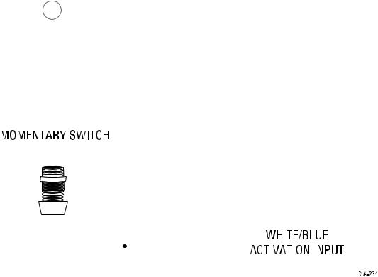
H1/4 |
WHITE/BLUE |
(-) ACTIVATION INPUT |
|
|
|
This input comes from the factory set to 1 activation pulse. This means that it is necessary to have 1 ground pulse on the white/blue wire for the remote start to activate or to deactivate. The same holds true for the remote control activation when set to a two pulse setting it is necessary to press the  button twice for the remote start to activate or deactivate.
Note: When the activation pulse count can be programmed to 1, 2, or 3 pulses when changed it will affect both activation inputs; the White/ Blue wire and the remote control activation.
|
|
|
|
|
|
|
|
|
|
|
|
|
|
|
|
|
|
|
|
|
|
|
|
|
|
|
|
|
|
|
|
|
|
|
|
|
|
|
|
|
|
|
|
|
|
|
|
|
|
|
|
|
|
|
|
|
|
|
|
|
|
|
|
|
|
|
|
|
|
|
|
|
|
|
|
|
|
|
|
|
|
|
|
|
|
|
|
|
|
|
|
|
|
|
|
|
|
|
|
|
|
|
|
|
|
|
|
|
|
|
|
|
|
|
|
|
|
|
|
|
|
|
|
|
|
|
|
|
|
|
|
|
|
|
|
|
|
|
|
|
|
|
|
|
|
|
|
|
|
|
|
|
|
|
|
|
|
|
|
|
|
|
|
|
|
|
|
|
|
|
|
|
|
|
|
|
|
|
|
|
|
|
|
|
|
|
|
|
|
|
|
|
|
|
|
|
|
|
|
|
|
|
|
|
|
|
|
|
|
|
|
|
|
|
|
|
|
|
|
|
|
|
|
|
|
|
|
|
|
|
|
|
|
|
|
|
|
|
|
|
|
|
|
|
|
|
|
|
|
|
|
|
|
|
|
|
|
|
|
|
|
|
|
|
|
|
|
|
|
|
|
|
|
|
|
|
|
|
|
|
|
|
|
|
|
|
|
|
|
|
|
|
|
|
|
|
|
|
|
|
|
|
|
|
|
|
|
|
|
|
|
|
|
|
|
|
|
|
|
|
|
|
|
|
H1/5 |
ORANGE |
|
|
|
|
|
|
|
|
(-) GROUND WHEN LOCKED OUTPUT |
|
|||||||||||||
|
|
|
|
|
|
|
|
|
|
|
|
|
|
|
|
|
|
|
|
|
|
|
|
|
This wire supplies a (-)500 mA ground as long as the system is locked and when the remote start is activated. (This feature can be turned off by programming the anti-grind option Off). This output ceases as soon as the system is unlocked. The GWA can be hooked up to an optional starter kill/anti-grind relay control module, a voice module or any accessory that requires a ground when armed.
16 |
© 2008 Directed Electronics. All rights reserved. |
 Loading...