

Avision @V6600 Service Manual

Network Scanner
Service Manual
(P/N: 253-0115-E)
Avision Inc.

ii
Contents
1. INTRODUCTION ....................................................................................... 1-1
1.1 GENERAL NOTES FOR SERVICING ................................................................. 1-1
2. SPECIFICATION ....................................................................................... 2-1
3. PRECAUTIONS OF INSTALLATION/TRANSPORTATION ................................. 3-1
3.1 PRECAUTIONS OF INSTALLATION ................................................................. 3-1
3.2 TRANSPORTATION.................................................................................. 3-1
4. THEORY OF OPERATION ............................................................................ 4-1
4.1 INTRODUCTION ..................................................................................... 4-1
4.2 MAIN CONTROL UNIT .............................................................................. 4-2
4.2.1 System Diagram ...................................................................... 4-2
4.2.2 SENSOR INPUT ........................................................................ 4-3
4.2.3 SUB POWER SUPPLY CIRCUIT ..................................................... 4-3
4.2.4 POWER SUPPLY ....................................................................... 4-4
5. PROBLEM SOLVING .................................................................................. 5-1
5.1 TROUBLESHOOTING FLOWCHART ................................................................. 5-2
5.1.1 POWER ON TO @V6600 READY ................................................... 5-2
5.1.2 E-MAIL OPERATION .................................................................. 5-3
5.1.3 FILING OPERATION .................................................................. 5-4
5.1.4 SCAN TO USB FLASH DRIVE OR PUBLIC FOLDER. ........................... 5-5
5.2 TABLES ............................................................................................. 5-6
5.2.1 LCD does not display ................................................................ 5-7
5.2.2 SCANNING IS NOT PERFORMED .................................................. 5-7
5.2.3 IMAGE UNCLEAR ...................................................................... 5-8
5.2.4 NOISE GENERATED .................................................................. 5-8
5.2.5 LCD DOES NOT SHOW MESSAGE AFTER COMMAND ........................ 5-9
5.2.6 THE PRODUCT IS NOT CONNECTED TO THE NETWORK.................... 5-9
5.2.7 INFORMATION MESSAGES DURING INITIATION OR SCANNING.........5-10
5.2.8 INFORMATION MESSAGES DURING NETWORKING .........................5-11
5.2.9 INFORMATION MESSAGES DURING E-MAILING .............................5-12
5.2.10 INFORMATION MESSAGES DURING FILING ...................................5-14
5.2.11 INFORMATION MESSAGES DURING SCAN TO USB DRIVE OR PUBLIC
FOLDER ................................................................................5-16

iii
6. DISASSEMBLY .......................................................................................... 6-1
6.1 SERVICE TOOL ..................................................................................... 6-1
6.2 PROCEDURE FOR DISASSEMBLY AND REASSEMBLY .............................................. 6-2
6.2.1 Notes on disassembly ............................................................... 6-2
6.2.2 Removing the ADF pad .............................................................. 6-3
6.2.3 Removing the ADF Roller ........................................................... 6-5
6.2.4 Removing the Output Tray ......................................................... 6-6
6.2.5 Removing the ADF Front Cover ................................................... 6-8
6.2.6 Removing the 2 Sensor Units on the front case .............................6-10
6.2.7 Removing the Sensor Board ......................................................6-14
6.2.8 Removing the ADF Board ..........................................................6-16
6.2.9 Removing ADF Chassis .............................................................6-17
6.2.10 Removing ADF Inverter ............................................................6-20
6.2.11 Removing ADF Motor ...............................................................6-22
6.2.12 Removing the Hinge ................................................................6-24
6.2.13 Removing the Metal Cover ........................................................6-26
6.2.14 Removing the Main Board .........................................................6-28
6.2.15 Removing the CF Card Board .....................................................6-30
6.2.16 Removing the Name Plate.........................................................6-31
6.2.17 Removing the Panel Main Board .................................................6-33
6.2.18 Removing the Panel Screen.......................................................6-36
6.2.19 Removing the Back Cover of the Panel ........................................6-38
6.2.20 Removing the Rubber Cap ........................................................6-40
6.2.21 Removing the Upper Housing ....................................................6-41
6.2.22 Removing the Metal Plate .........................................................6-43
6.2.23 Removing the Sliding Rod .........................................................6-44
6.2.24 Removing the Flatbed Chassis ...................................................6-45
6.2.25 Removing the Chassis Cover .....................................................6-46
6.2.26 Removing the Motor ................................................................6-47
6.2.27 Removing the Inverter .............................................................6-50
6.2.28 Removing the Lamp Assembly ...................................................6-53


Service Manual
1-1
1. INTRODUCTION
General Notes for Servicing
General Description
The manual describes areas to be maintained, the detailed installation, the disassembly,
and the component replacement procedures as well as the main trouble shooting guides.
Please take your time to read this manual thoroughly to obtain comprehensive knowledge
about the scanner before serving the unit.
1.1 General notes for servicing
(1) Before trying to disassemble the scanner, make sure the power supply cord of the
scanner is disconnected from the power outlet. Under any circumstance, do not
remove or install the connectors on the scanner with the power supply turned ON.
(2) Use caution not to drop small parts or screws inside the unit when disassembling and
reassembling. If left inside, they might cause the malfunction of the unit.
(3) Do not pull the connector cable when disconnecting it. Hold the connector.
(4) When carrying the scanning head unit, put it in an anti-static bag.
(5) Keep the document table glass surface always clean. If contaminated, use a dry
clean cloth for cleaning.
(6) Use caution not to injure your fingers or hands when disassembling or reassembling
the unit.


2-1
2. SPECIFICATION
Model Name
@V6600
Product Type
Legal size Flatbed + DADF (Dual Reading Head
Duplex ADF)
Optical Resolution
600 x 600 dpi
Adaptor Input Voltage
AC 100~240V
Adaptor Output
24V DC, 3.2A
CPU
400 MHz, Toshiba x4939 (MIPS64)
Scanner ASIC / Image
Processor
124 MHz, visionMax 800 * 2
DSP Co-Processor
500 MHz, SPI SP-16
Memory Size
896 Mbytes DRAM in total
System: 128MB
Scanner/Image Buffer: 256MB
DSP: 512MB
Flash Memory Size
40.5 Mbytes in total
System: 8.5Mbytes
DSP: 32 Mbytes
Built-in CF Card Storage
8/16Gbytes
LCD display
7” color TFT LCD
800*480 dots
Effective Area: 152.4 * 91.44 mm
With Touch Panel
Specifications
Service Manual

2-2
Connectivity (External Ports)
USB 2.0 Device * 1
USB 2.0 Host * 2 (on Rear Panel)
USB 2.0 Host * 1 (on Front Panel)
RJ-45 Network Connector * 1
Dimensions (W x D x H)
531 x 484 x 401 mm3 (with ADF)
Weight
12.92 Kgs (With ADF)
Maximum Scanning Area
(Flatbed)
8.5” x 14”
Document Set Reference
Left upper corner
Life
Scanner life(Flatbed)
Lamp life
50,000 scans or 5 years
More than 10,000 hours
Acoustic Noise
46 dB
MTBF
5,000 hours
Type
U-shape, Dual-Head Duplex
Capacity
50 sheets
Document Size
4.5” x 5.5” ~ 8.5” x 14”
Paper Feed
Face Up
Paper Weight
16 lb ~ 28 lb (60g/m2 ~ 105 g/m2)
0.002”~0.006”
Multi-Feed Detect
Yes
ADF life
600,000 scans or 5 years, whichever comes first
Recommended Pad
Replacement
30,000 scans
Customer Replaceable
Recommended Roller
Replacement
200,000 scans
MTBF
5,000 hours
Network Topology
10/100/Gigabit Ethernet
Connectivity
RJ-45 UTP connector

Service Manual
2-3
Protocol
TCP/IP, DHCP
802.1x, SSL/TLS
DNS, DDNS, SNTP
LDAP, LDAP-SSL, SLP,
SMTP, HTTP, HTTPS, MIME, FTP, FTPS, CIFS(SMB)
HTTP Server
, Port9100
Connection Configuration
1. Enable DHCP or
2. assign physical IP address:
IP address
IP subnet mask
IP Gateway
Device URL
Same as Information/Device Name
Security
IEEE802.1x, SSL/TLS


Service Manual
3-1
3. PRECAUTIONS OF
INSTALLATION/TRANSPORTATION
Precautions of Installation
Transportation
3.1 Precautions of Installation
Pay attention to the following matters before unpacking and installation.
Do not install in a place where vibration may occur.
Keep the scanner out of direct sunlight. Do not install near a heat source.
Do not place the scanner around materials which shut off the circulation of air.
Do not install in a humid or dusty place.
Use care not to scratch the glass surface of the scanner or the document holding
pad with a clip or staple.
Do not use the wall socket with connecting devices which may generate noise, for
example, air-conditioner, etc.
Use a suitable AC power source.
Place the scanner on a level surface.
3.2 Transportation
To move the scanner from where it is installed, for repair or any other reason, make
sure to observe the following conditions:
(1) Turn off the power of the scanner.
(2) Remove the power cable and lock the scanner.
(3) Put the scanner in the packing case with the packing material.

4-1
Main
Board
1 0 0 1 0
Cold Cathode
Lens
CCD
Analogue
Signal
Digital
Signal
Fluorescent Lamp
Image
Processor
CPU
Reflected
Rays
TouchScreen
CPU
ASIC
Ethernet
SMTP
/Filing
Server
PC Scan
Ethernet
USB
Host
USB flash
drive
RJ-45
USB Device
Email
Filing
NetworkPrint
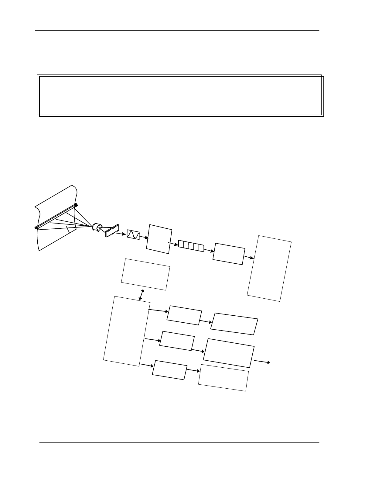
4. THEORY OF OPERATION
Introduction
Main Control Unit
4.1 Introduction
Figure 4.1 Theory of formation of image.
Service Manual

4-2
The reflected rays of your original as shown in the above figure pass through the lens and
create an image on the CCD (Charged Coupled Device). Then, according to the different
light intensity perceived by the CCD, the CCD will transfer these data into a series of
analog signals to the main board, where the signals are turned into digital signals. The
digital signals flow to the image processor and store into the CPU (Central Processing
Unit). Through the commands from the Panel, the digital signals may goes to 4939
Controller to RJ-45 to the SMTP or filing server to send an email or store an image via
entherne , or to remote printer to make digital copy via enthernet, as well as allow to usb
flash drive or CF card ( removable storage) through usb host.
4.2 Main Control Unit
4.2.1 System Diagram
The following shows the system block diagram.
Figure 4.2 Product System Block Diagram

Service Manual
4-3
Switching
Regulator
+24V
+1.5V
+2.5V
+1.25V
+1.8V
+ 3.3 V
+ 32V
+ 16V
Linear
Regulator
+24V
+12V
4.2.2 SENSOR INPUT
The sensor input includes home position sensor.
Home position sensor
The home position of the carrier motor is detected by photo sensor. The photo transistor
transmission to the photo sensor receiver circuit is shown below.
Figure 4.3 Home Sensor
The home position is detected when the carrier passes between the LED and the photo transistor.
4.2.3 SUB POWER SUPPLY CIRCUIT
The sub power supply circuit is provided for the internal analog circuit. Input is 24V and
output is Vcc and +5Va. The circuit configuration is shown below:
Figure 4.4 Power Aupply Circuit Configuration
The sub power supply is used for: A/D, and logic circuits.

4-4
Type
Characteristic
Wall-mount
Input voltage range
100-240V
Input current(max.)
1.0~1.7A
Input frequency
50-60Hz
Output voltage
+24Vdc
Max. load current
3.2A
Output Wattage
76.8W
4.2.4 POWER SUPPLY
In this system, there is only one type of power supply. Please see the following table for
details.
Table 4.5 Power Adapter

Service Manual
5-1
5. PROBLEM SOLVING
Diagnostics
Troubleshooting
This section is given to locate and resolve the causes of troubles so as the product is always
in good working condition. The trouble modes, relevant units and maintenance methods are
described below.
When a problem occurs, troubleshoot the problem according to the symptoms it shows.
Check the following first:
1. Is anything being operated improperly?
2. Does the problem recur, or is it regular?
The sections, 5.1.1 to 5.1.4, show the troubleshooting flowcharts.
The causes and maintenance methods for each failure mode are described in Table 5.1
through 5.11

5-2
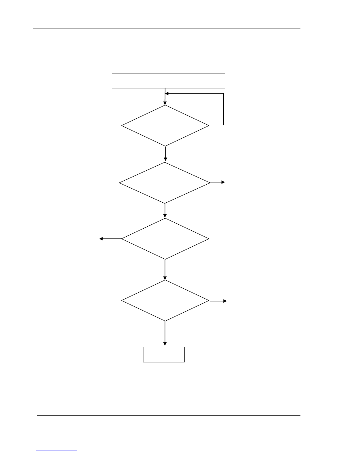
Power on
Screen shows
Warming up
Message
No
Yes
See Table 5.1 or
Table 5.7
Screen shows
Default working mode
Yes
5.1 Troubleshooting Flowchart
5.1.1 POWER ON TO @V6600 READY
5-3
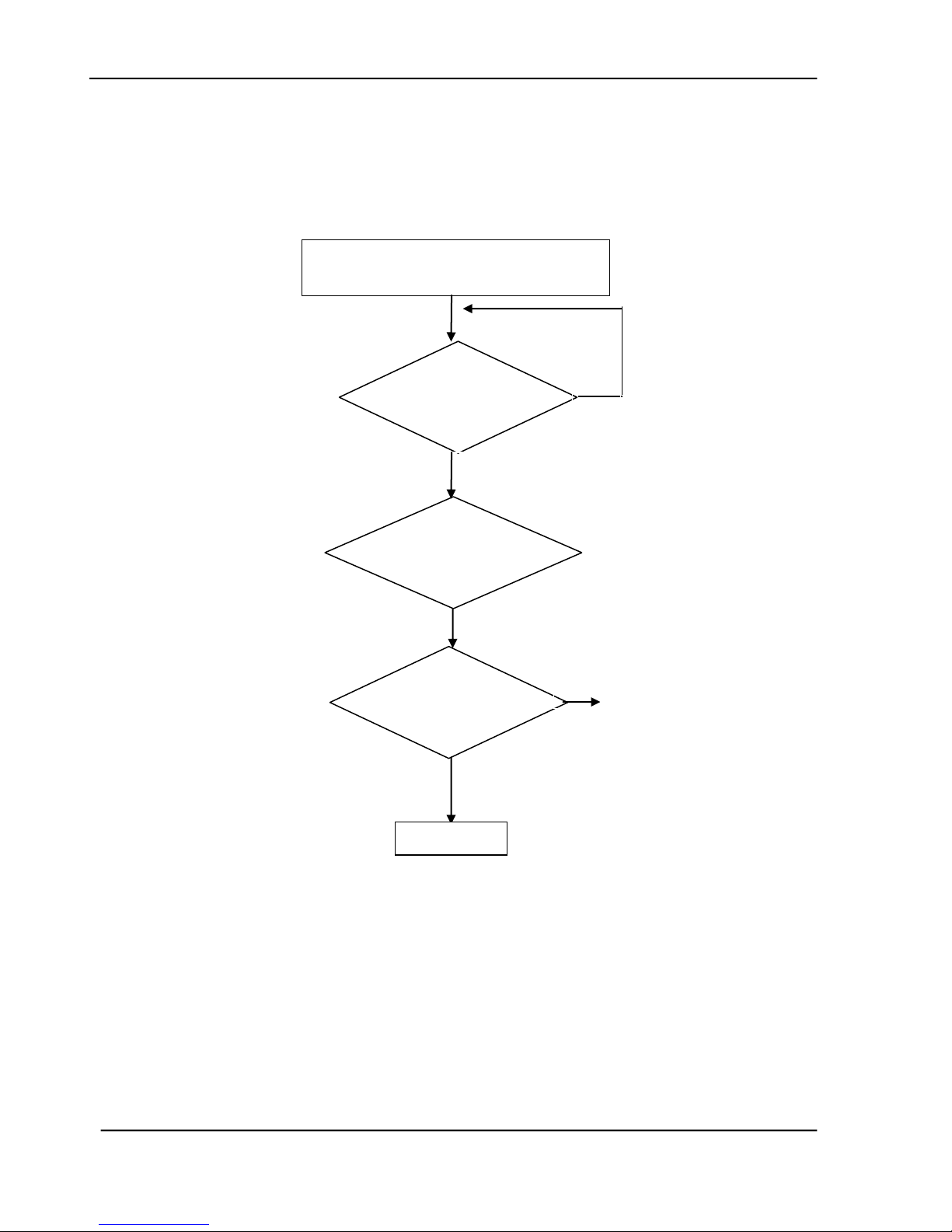
Email Online Troubleshooting
Yes
Yes
Yes
See Table 5.3
No
No
Yes
Press the
Mono/Color
button?
Connect SMTP
server and start
scanning?
Send the
scanned image?
Transferring
completed ?
END
No
No
See Table 5.8
Or
5.2.10 Info. Message During Networking
5.2.11 Info. Message During E-Mailing
See Table 5.8
Or 5.2.10 Info. Message During Networking
5.2.11 Info. Message During E-Mailing
5.1.2 E-MAIL OPERATION
Service Manual

5-4
See Table 5.8
Or 5.2.10 Info. Message During Networking
5.2.12 Info. Message During Filing
Yes
Yes
See Table 5.3
See Table 5.8
Or 5.2.10 Info. Message During Networking
5.2.12 Info. Message During Filing
Yes
Filing Online Troubleshooting
Press the
Mono/Color
button?
Send the
scanned image?
Transferring
completed ?
END
No
No
Yes
Connect FTP/HTTP/HTTPS/CIFS
server and start scanning?
No
5.1.3 FILING OPERATION
5-5
Scan to USB flash drive or Public folder
Online Troubleshooting
Press the
Mono/Color
button?
Yes
Start scanning?
Save the
scanned image?
END
No
See Table 5.2.13
INFORMATION MESSAGES
DURING SCAN TO USB
DRIVE OR PUBLIC FOLDER
No
5.1.4 SCAN TO USB FLASH DRIVE OR PUBLIC FOLDER.
Service Manual

5-6
Table 5.1
The LCD does not display
Table 5.2
Scanning Is not Performed
Table 5.3
Image not clear
Table 5.4
Noise generated
Table 5.5
LCD does not show message after
command
Table 5.6
The product is not connected to the
network
5.2 Tables
The following tables provide detailed troubleshooting information.

5-7
Cause
Relevant
Unit
Check
Method
Maintenance
Method
Unplugged
from outlet
None
Visual check
Insert the AC plug into
the outlet
DC power
unplugged
from unit
None
Visual check
Insert the DC power
adapter cable into the
unit
AC voltage
failure
None
AC outlet
voltage
check
None
Power adapter
output voltage
failure
Power unit
Output
voltage
(+24v) check
Replace the power
unit
PCB failure
Main control
PCB
Tester check
(+24V, GND)
Remove the cause or
replace the PCB
LCD module
main board
connection
failure
LCD module
main board
Visual check
Plug the connector and
secure it firmly
Cause
Relevant
Unit
Check
Method
Maintenance Method
Scanner USB
cable failure
Scanner
USB cable
Visual check
Attach the scanner USB
cable
Scanner link
failure
Main PCB
Visual check
Replace the PCB
Optical
Chassis
Replace the Optical
Chassis
5.2.1 LCD does not display
Service Manual
Table 5.1
5.2.2 SCANNING IS NOT PERFORMED
Table 5.2

5-8
Cause
Relevant
Unit
Check
Method
Maintenance Method
Lamp too
dark
Lamp
Visual check
Replace the lamp
Dirt on
flatbed glass
Flatbed
glass
Visual check
Clean the
flatbed glass with isopropyl
alcohol
Printer toner
low
Printer toner
Visual check
Check printer toner or
replace the toner
Printer
memory not
enough
Printer
Visual check
Add printer memory
Cause
Relevant
Unit
Check
Method
Maintenance Method
Motor unit
failure
Motor unit
Replace the
motor unit
Replace the motor
Main control
PCB failure
Main control
PCB
Replace the
main control
PCB
Replace the main control
PCB
Optical
chassis
failure
Optical
chassis
Check optical
chassis
shakiness
Replace the optical
chassis
Dirt on rail
None
Visual check
Clean the rail
with oil
5.2.3 IMAGE UNCLEAR
5.2.4 NOISE GENERATED
Table 5.3
Table 5.4

5-9
Cause
Relevant unit
Check method
Maintenance method
LCD module
cable failure
Panel cable
Visual check
Attach the LCD module
cable and
secure it firmly
LCD problem
LCD PCB
Replace the LCD
PCB
Replace the LCD PCB
Push button
failure
Panel PCB
Replace the panel
PCB
1. Check the panel
cable and secure it
firmly.
2. Replace the panel
PCB.
Cause
Maintenance Method
RJ-45 connector is not plugged
in
Plug the connector in.
Network cable is damaged
Replace a good one
IP address is invalid
Ask your network administrator for a valid
address.
Subnet Mask is invalid
Ask your network administrator for a valid
value.
Gateway IP is invalid
Ask your network administrator for a valid
address.
5.2.5 LCD DOES NOT SHOW MESSAGE AFTER COMMAND
Table 5.5
5.2.6 THE PRODUCT IS NOT CONNECTED TO THE NETWORK
Service Manual
Table 5.6

5-10
Message
Action
FB/ADF Home
sensor error
Restart your product.
If the code still appears, check optical chassis. If optical
chassis is malfunction, replace it.
FB/ADF Lamp
error
Restart your product.
If the code still appears, check lamp, inverter or main board.
If one of them is malfunction, replace it.
ADF paper jam
ADF paper jam.
Open the ADF cover and remove the paper from the ADF
then restart your product.
If the code still appears, check if paper-in sensor, paper-out
sensor, main board, or the AV board is malfunction. If one
of them is malfunction, replace it.
Release The
Sensor Lock
Optical Chassis is locked.
1. Turn off your product.
2. Find the lock switch underneath the machine and unlock
the machine.
3. Restart your product.
If the code still appears, check main board. If main board
is malfunction, replace it.
ADF Cover
Open
1. Close ADF Cover.
2. Follow instruction on screen.
ADF MultiFeed
Open the ADF cover and remove the paper from the ADF
then restart your product.
If the code still appears, check if ultrasonic, paper-in sensor,
paper-out sensor, main board, or the AV board is
malfunction. If one of them is malfunction, replace it.
FB Cover Open
1. Close FB Cover.
2. Follow instruction on screen to restart your product.
Scanner
Synchronization
Error
1. Check if ADF cable is tightly attached.
2. Follow instruction on screen to restart your product.
3. If the code still appears, check main board. If main
board is malfunction, replace it.
5.2.7 INFORMATION MESSAGES DURING INITIATION OR SCANNING
Table 5.7
 Loading...