

Page 1

LNT
Programmer’s
Manual using XML
® 6057 Printer
® 6140 Printer
TC6057LNTPM Rev AG
4/14
©2011 Avery Dennison Corp. All rights reserved.
Page 2

Each product and progr am carries a respective written warranty, the only warrant y on which
the customer can rely. Aver y Dennison Corp. reserves the rig ht to make changes in the
product, the programs, and their availability at any time and without notice. Althoug h Avery
Dennison Corp. has made every ef fort to provide complete and accurate information in this
manual, Avery Dennison Corp. shall not be liable f or any omissions or inaccurac ies. Any
update will be incorpora ted in a later edition of t his manual.
©2011 Avery Dennison Cor p. All rights reserved. No part of this publication may be
reproduced, transmitted , stored in a retrieval system , or translated into any languag e in any
form by any means, without t he prior written permission of Avery Dennison Corp.
Trademarks
Avery Dennison® and Pathfinder® are reg istered trademarks of Avery Denniso n Corporation.
Bluetooth® is a registered t rademark owned by Bluetooth SIG , Inc.
Avery Dennison
170 Monarch Lane
Miamisburg, OH 45342
Page 3

TABLE OF CONTENTS
INTRODUCTION .............................................................................................................................. 1-1
About the Printers ...................................................................................................................... 1-1
Creating a LNT File .................................................................................................................... 1-1
Standard Syntax Guidelines ........................................................................................................ 1-2
Using This Manual ...................................................................................................................... 1-2
Related Documentation ............................................................................................................... 1-3
Supported File Types.................................................................................................................. 1-3
Transferring Files to the 6057 Printer .......................................................................................... 1-3
Using Fonts with the 6057 Printer ................................................................................................ 1-6
Using Non-Resident Fonts ....................................................................................................... 1-6
Installing Fonts ....................................................................................................................... 1-6
Error Reporting with the 6057 Printer ........................................................................................... 1-6
Enabling the “Field Off Tag” Warning ........................................................................................ 1-7
Transferring Files to the 6140 Printer .......................................................................................... 1-7
Error Reporting with the 6140 Printer ........................................................................................... 1-7
LNT Design Tips ........................................................................................................................ 1-8
DEFINING PRI NTER SETUP XML TAGS............................................................................................ 2-1
Defining Printer Setup Tags ........................................................................................................ 2-1
Defining the Job Container (Required) ...................................................................................... 2-1
Defining the LabelSize Tag (Required) ..................................................................................... 2-1
Defining the Energy Tag (Optional) .......................................................................................... 2-2
Defining the Contrast Tag (Optional) ........................................................................................ 2-2
Defining the PrintSpeed Tag (Optional)..................................................................................... 2-2
Defining the UseBlackMark Tag (Optional) ................................................................................ 2-3
Defining the UseOnDemand Tag (Optional for 6057) .................................................................. 2-3
Defining the SensorMode Tag (Optional)................................................................................... 2-3
Defining the Quantity Tag (Optional) ........................................................................................ 2-3
Def
ining the Image Container (Required) ..................................................................................... 2-4
Defining the ImageSize Tag (Required) .................................................................................... 2-4
Adjusting the Supply Position ...................................................................................................... 2-6
Setting a Negative Supply Position (Using Backfeed) ................................................................. 2-6
Introduction i
Page 4

DEFINING FIEL D SETUP XML TAGS ................................................................................................ 3-1
Defining the Fields Container (Required) ...................................................................................... 3-1
Defining the TextField (Required) ............................................................................................. 3-1
Defining the BoundingBox Tag (Required for non-barcode fields) .............................................. 3-2
Defining the Data Tag (Required)............................................................................................ 3-2
Defining the Volatile Tag (Required) ....................................................................................... 3-3
Defining the Rotation Tag (Optional) ....................................................................................... 3-3
Defining the DrawMode Tag (Optional) .................................................................................... 3-4
Defining the Font Tag (Optional) ............................................................................................. 3-5
Defining the VerticalJustification Tag (Optional) ....................................................................... 3-8
Defining the HorizontalJustification Tag (Optional) ................................................................... 3-8
Defining the BackgroundColor Tag (Optional) .......................................................................... 3-8
Defining the ForegroundColor Tag (Optional) ........................................................................... 3-9
Defining the BarcodeField (Required) ..................................................................................... 3-10
Defining the Data Tag (Required).......................................................................................... 3-10
Defining the Volatile Tag (Required) ..................................................................................... 3-10
Defining the Origin Tag (Required) ........................................................................................ 3-11
Defining the BarHeight Tag (Required) .................................................................................. 3-12
Defining the Type Tag (Required) ......................................................................................... 3-12
Defining the Orientation Tag (Optional) ................................................................................. 3-12
Defining the Options Tag (Optional) ...................................................................................... 3-12
Defining the LineField Tag (Required) .................................................................................... 3-13
Defining the Offset1 Tag (Required) ...................................................................................... 3-13
Defining the Offset2 Tag (Required) ...................................................................................... 3-13
Defining the Thickness Tag (Required) .................................................................................. 3-14
Defining the BoxField Tag (Required) ..................................................................................... 3-15
Defining the Box Tag (Required) ........................................................................................... 3-15
Defining the Line Thickness Tag (Required)........................................................................... 3-16
ining the DrawMode Tag (Optional) .................................................................................. 3-16
Def
Defining the LineColor Tag (Optional) ................................................................................... 3-16
Defining the FillColor Tag (Optional) ..................................................................................... 3-16
Defining an EllipseField (Required) ........................................................................................ 3-17
Defining the BoundingBox Tag (Required) ............................................................................. 3-17
Defining the Line Thickness Tag (Required)........................................................................... 3-18
Defining the DrawMode Tag (Optional) .................................................................................. 3-18
Defining the LineColor Tag (Optional) ................................................................................... 3-18
Defining the FillColor Tag (Optional) ..................................................................................... 3-18
Defining a GraphicField (Required) ........................................................................................ 3-19
Defining the Volatile Tag (Required) ..................................................................................... 3-19
Defining the BoundingBox Tag (Required) ............................................................................. 3-19
Defining the Data Tag (Required).......................................................................................... 3-20
Defining the DrawMode Tag (Optional) .................................................................................. 3-20
Defining the VerticalJustification Tag (Optional) ..................................................................... 3-20
Defining the HorizontalJustification Tag (Optional) ................................................................. 3-20
ii LNT Programmer’s Manual
Page 5

DEFINING BAR CO DE OPTIONS ...................................................................................................... 4-1
Scannable Bar Codes vs. Printable Bar Codes .............................................................................. 4-1
Defining the Codabar Options Tag (Optional) ............................................................................... 4-2
Defining the Code 16K Options Tag (Optional) ............................................................................. 4-2
Defining the Code 39 Options Tag (Optional) ................................................................................ 4-3
Defining the Code 93 Options Tag (Optional) ................................................................................ 4-4
Defining the Code 128 Options Tag (Optional) .............................................................................. 4-4
Defining the Interleaved 2of5 Options Tag (Optional) .................................................................... 4-5
Defining the MSI Options Tag (Optional) ...................................................................................... 4-6
Defining the UPCA/UPCE/EAN Options Tag (Optional) .................................................................. 4-6
Defining the Data Matrix Options Tag (Optional) ........................................................................... 4-7
Defining the GS1 DataBar Options Tag (Optional) ......................................................................... 4-8
Defining the MaxiCode Options Tag (Optional) ............................................................................. 4-9
Defining the Data Tag (Required) ............................................................................................. 4-9
Defining the Micro PDF417 Options Tag (Optional) ..................................................................... 4-11
Defining the PDF417 Options Tag (Optional) .............................................................................. 4-12
Defining Data for POSTNET (Optional) ...................................................................................... 4-12
Defining the Quick Response Options Tag (Optional) .................................................................. 4-13
Using MPCLSTYLE for the Quick Response Bar Code .............................................................. 4-14
Defining the Data Tag (Required).......................................................................................... 4-14
CREATING JOB DATA ..................................................................................................................... 5-1
Defining the JobData Container (Required) .................................................................................. 5-1
Defining the Field Container (Optional) ..................................................................................... 5-1
Defining Printer Setup XML Tags ................................................................................................. 5-2
Defining the Quantity Tag (Optional) ........................................................................................ 5-2
Defi ning the Energy Tag (Optional) .......................................................................................... 5-2
Defining the Contrast Tag (Optional) ........................................................................................ 5-2
Defining the PrintSpeed Tag (Optional)..................................................................................... 5-3
ining the UseBlackMark Tag (Optional) ................................................................................ 5-3
Def
Defining the UseOnDemand Tag (Optional for 6057) .................................................................. 5-3
Defining the SensorMode Tag (Optional)................................................................................... 5-3
Sample JobData File .................................................................................................................. 5-4
ERROR MESSAGE S ........................................................................................................................ 6-1
Hard Printer Errors .................................................................................................................. 6-3
SAMPLE LNT FILES ....................................................................................................................... A-1
Code 39 Bar Code with Text Sample ........................................................................................... A-1
Fixed Field Sample .................................................................................................................... A-2
Text Field Sample ..................................................................................................................... A-3
International Font Sample .......................................................................................................... A-3
DESIGN TOOLS ............................................................................................................................. B-1
Origin (Millimeters) .................................................................................................................... B-2
Origin (Inches) .......................................................................................................................... B-3
Introduction iii
Page 6

CODE PAGES ................................................................................................................................ C-1
Supported Code Pages .............................................................................................................. C-1
Code Page 0 (Internal) .............................................................................................................. C-1
Code Page 100 (Macintosh) ....................................................................................................... C-2
Code Page 101 (Wingdings) ....................................................................................................... C-2
INDEX............................................................................................................................................. I-1
iv LNT Programmer’s Manual
Page 7

1
INTRODUCTION
This manual is for the develo per who is creating and designi ng custom labels for the
♦ Pathfinder® 6057 printer.
♦ Pathfinder® 6140 printer.
Note: You must develop an applicat ion that uses the f iles you create.
About the Printers
The 6057 Software Development Kit (SDK) helps dev elopers write applications f or the 6057
printer. This printer oper ates on a Microsoft® W indows-base d CE platform.
The 6140 printer is des igned to support diff erent operating systems. Eac h operating system
will have its own SDK. For example, the 6140 iOS SDK helps d evelopers write applicat ions for
their smart device. The 6140 pri nter with Bluetooth® can be p aired/connected with a smart
device to scan bar codes and pri nt labels. Refer to the Sample Application (Scan and Print)
included with the iOS SDK for more information.
To print labels/tags on either printer, a LNT (Lang uage Neutral Template) file must be cr eated.
This manual describe s how to create a LNT f ile.
Creating a LNT File
The LNT (Language Neutral Template) fi le defines how your label lo oks – what t ype of
information appears ( text, bar code, line or gr aphic fields) and where they print on t he label.
The LNT file uses XML Version 1.0 pr ogramming.
LNT files must contain
♦ printer setup XML tags
♦ field setup XML tags.
Printer setup tags define t he print speed, print cont rast, label size, and
image size. Field setup tag s define the look of the label (incl uding text,
bar code, line or box f ields).
For example, the label sho wn on the right contains three f ield setup
tags: one for the text field “PR ETZELS,” one for the UPCA bar code
field, and one for the price t ext field “$.79.”
Introduction 1-1
Page 8
Standard Syntax Guidelines
Each LNT file must start with t he XML declaration:
<?xml version="1.0" encoding="UTF-8" ?>
To add comments in an LNT f ile:
<!-- start of comment
--> end of comment
<!—for Code 39 barcodes -->
To comment an entire field:
<!- <BarcodeField id="Code39BC">
<Volatile>1</Volatile>
<Origin units="Inches" x="0.800" y="0.170" justification="Center" />
<BarHeight units="Inches">0.500000</BarHeight>
<Orientation>0</Orientation>
<Type>code39</Type>
<Options density="12" />
<Data max="20" min="0" />
</BarcodeField>
-->
Using This Manual
Following is a summary of t he contents of this manual:
Chapter Contents
1
Introduction Information you should k now before programming the printer.
Defining the Printer
2
Setup XML Tags
Defining Fie ld
3
Setup XML Tags
Defining Bar Code
4
Options
5
Creating Job Data Defines the data printed in eac h field on the supply.
6
Error Messages
A
Sample LNT File s Contains sample LNT files.
B
Design Tools Contains copies of work sheets/grids to layout a LNT file.
C
Code Pages Contains a listing of the code pages the printers support .
Defines the printer setup tags in XML.
Defines the field setu p tags in XML.
Defines options that appl y to each bar code type.
Contains a list of err or messages you may receive while using the
printer.
1-2 LNT Programmer’s Manual
Page 9

Item
Description
Related Documentation
The following table descr ibes other documentation f or the printer:
Quick Refere nce
Operator ’s Handbook
or
Equipment Manual
System Administrator’s
Guide
Includes bas ic start-up informat ion such as supply loa ding, clean ing
and minor troubleshooting.
Includes inform ation about usi ng the printer, c harging the batter y,
loading supplies, and more.
Includes inform ation about pri nter diagnostics , configuring the
scanner, and us ing scanner dia gnostics.
Supported File Types
The printer supports file t ypes with these extensions:
File Extension Description
bmp
gif
jpg
png
fon
fnt
ttf
job
lnt
xml
Bitmap Gra phics
Graphic Int erchange Fo rmat
JPEG/JIFF Image
Portable Network Graphic
Font (Micros oft)
Font
TrueType® Font
Job File
Language Ne utral Templ ate
Extensible M arkup Language
Note: The L NT file can also be s aved as a .JO B or .XML file.
Sample LNT fil es are included in th e
Device (printer).
\Windows\Resources\ LNTs folder on the 6057 Mobile
Transferring Files to the 6057 Printer
This section is not applic able to the 6140 printer. See “Transferring
Files to the 6140 Printer” for mor e information.
To transfer data f iles to the 6057 printer, use Microsoft® ActiveSync or
Windows® Mobile® Device Center. These instructions are written for
Microsoft® ActiveSync:
1. Open t he folder with your data files on yo ur computer.
2. Turn on the printer and wait f or the desktop to load.
3. Connect the USB cable to your compute r and printer.
4. Microsoft® ActiveSync automatical ly detects your printer. W hen
prompted to set up a Partners hip, select No, then click Next.
Introduction 1-3
Page 10
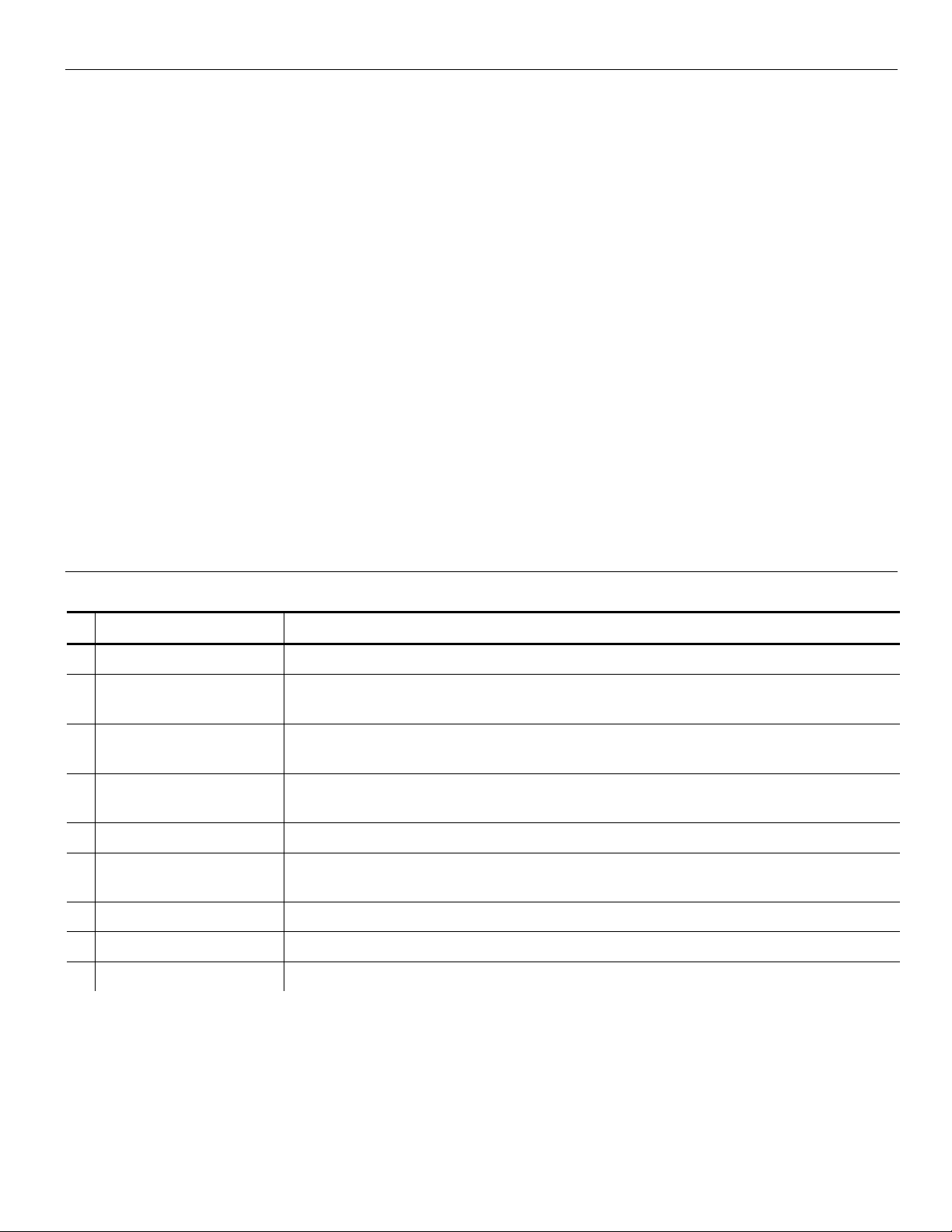
5. Click Explore on the Act iveSync utility after it connects to the printer. A new windo w
appears called Mobile Device.
6. Open t he destination folder f or the data files on the Mobile Devic e (printer).
7. Drag the files from your computer to t he Mobile Device folder.
To test a LNT file with fixed data, sa ve it to the Mobile Device’s (printer’s) Temp\Print
folder.
To permanently save an y file to the Mobile Device (printer), save it to t he Temp\Install
folder.
Make sure supplies are loade d, you have a fully charged batter y, the printer is connected t o a
host and ready to receive data, and you have an application in the pr inter. Refer to your
Operator’s Handbook f or more information.
1-4 LNT Programmer’s Manual
Page 11
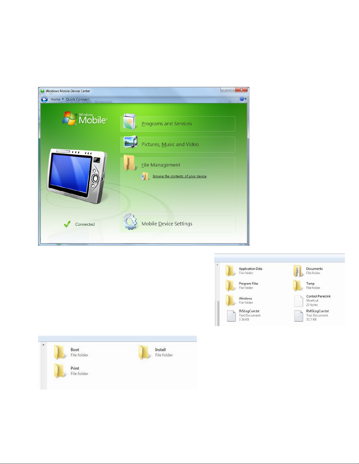
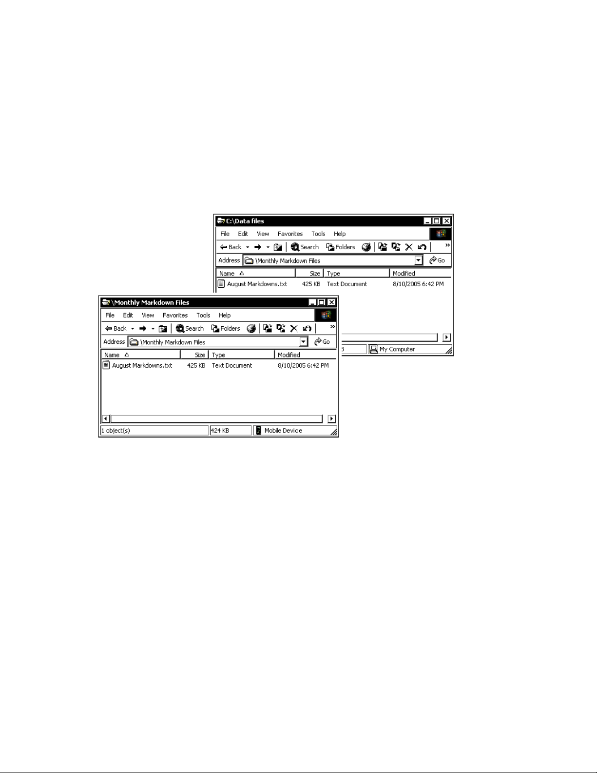
These instructions are wr itten for Windows® Mobile® Device C enter:
1. Open t he folder with your data files on you r computer.
2. Turn on the printer and wait for the desktop to load.
3. Connect the USB cable to your compute r and printer.
4. Windows® Mobile® Device Center autom atically detects your pri nter. Click Connect
without sett ing up your device to continue.
5. Click File Management, then click Browse the content s of your device.
6. Select your device.
7. Open t he destination folder f or the data files on the
Mobile Device (printer) .
8. Drag the files from your computer to t he Mobile
Device folder.
To test a LNT file with f ixed data, save it to the
Mobile Device ’s (printer ’s) Temp\Print folder.
To permanently save an y file to the Mobile
Device (printer), save it to the Temp\Install folder.
Make sure supplies are loade d, you have a fully charged batter y, the printer is connected t o a
host and ready to receive data, and you have an application in the pr inter. Refer to your
Operator’s Handbook f or more information
Introduction 1-5
Page 12
ID:BOX1, BoxField:L ineThickness
Using Fonts with the 6057 Printer
This section is not applic able to the 6140 printer. See “Transferring Files to t he 6140 Printer”
for more information.
The printer uses standard W indows fonts; however, add itional fonts can be downlo aded to the
printer. See “
Using Non-Resident Fonts
Within your applicatio n, instantiate a new Print class s uch as rPrint and call a method such as
Print to load the non-resident.
Installing Fonts
Follow these steps to install additional W indows fonts to the printer:
1. Make sure the printer is connected via USB and start a n Active Sync session.
2. Open t he \WINDOWS\Fonts f older on your computer .
3. Drag the TrueType® font file (. TTF) from your computer to the Te mp\Install folder on the
Mobile Device (printer) .
Note: Check the \Windows\ Resources\Fonts folder on the Mobile Device (printer) to make
sure the file installed c orrectly. Do not save f iles directly to this f older.
Installing Fonts” f or more information.
4. Ref erence the font’s filename in the L NT file. See “
more information about c reating a text field with an i nstalled font.
Note: The printer’s software (version 2.0 or higher) supp orts International
(double-byte) font s. An International TrueType font containing Chinese or Japanese
characters may be very large. Make sure the printer has enoug h memory before
installing the f ont.
Defining the Font Tag (Optional)” for
Error Reporting with the 6057 Printer
This section is not applic able to the 6140 printer. Refer to the Sof tware Development Kit
(SDK) for more information.
During normal printer oper ation or while te sting a LNT f ile, you may receive an error mes sage.
When an error occurs, a messag e appears briefly on the displa y “Press home key to clear the
printer error” and a small sto p sign icon appears in the Task Bar.
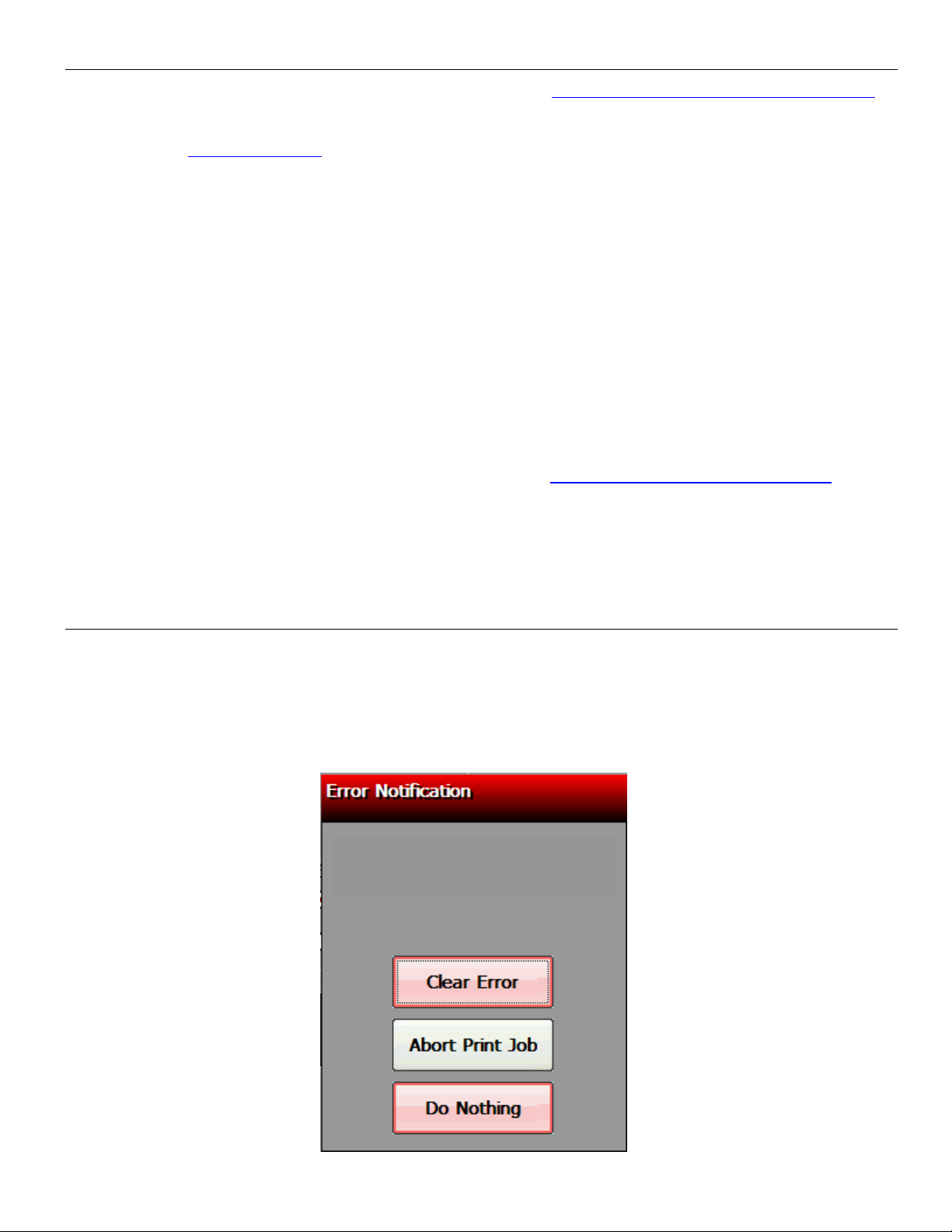
1. Press the Home k ey to show the error message. For example:
Parser Error
1-6 LNT Programmer’s Manual
Page 13

2. Select the option you need: Clear Error (clears the error and continues to f eed or print
supplies), Abort Print Job ( clears the error and cancels the cur rent print job), or Do
Nothing (does not cle ar the error or reprint the job) .
The example above, “Parser Er ror ID:BOX1,BoxField:LineT hickness” indicates a pars er
error in the LNT file. The BO X1 field contains an invalid <LineThickness> tag o r is
missing the <LineThickness> tag.
Touch Clear Error, corr ect the LNT file, then resend t he file to the printer. See
“
Defining the Line Thick ness Tag (Required)” f or more information about defining the
line thickness of box fields .
See Chapter 6, “
Note: If there is an error in a LNT f ile, it does not print.
Error Messages” f or a listing of error codes.
Enabling the “Fie ld Off Tag” Warning
The printer can display error 614 when a field is positione d outside the printable area. The
default does not generat e this warning.
To enable:
1. Touc h the Home key.
2. Select Printer Config .
3. Select General Settings.
4. Check Generate Off Tag Warnings.
5. Touch OK when finished.
Note: 614 Errors are not reported when t his is not
enabled – on ly correctly posit ioned fields within
the printable area are printed.
Transferring Files to the 6140 Printer
Your application contro ls the use of LNT, font, or other supported file types.
For example, to add a LNT f ile (or font file) to your applicat ion, use the SaveResourceAtPath
method, which saves a f ile to the smart device.
[ADResourceManager SaveResourceAtPath:[[NSBundle mainBundle] pathForResource:@"Markdown.LNT"
ofType:nil] type:ADResourceMediaTypeLnt alias:@"label"];
[ADResourceManager SaveResourceAtPath:[[NSBundle mainBundle] pathForResource:@"Arial Bold.ttf"
ofType:nil] type:ADResourceMediaTypeFont alias:@"Arial Bold"];
For example, to remove a LNT file (or font file) from your application, use the
RemoveResourceOfType met hod, which removes a file f rom the smart device.
Note: Refer to the Sample Application (Scan and Pr int) included with the iOS Soft ware
Development Kit f or more inform ation.
Error Reporting with the 6140 Printer
During normal printer oper ation, you may receive an error m essage. When an error occurs, a
message appears on the smart device. Follow the instructions on the smart device and press
Feed/Clear Error on the pr inter to clear the error an d continue.
Introduction 1-7
Page 14

LNT Design Tips
When creating LNT files, keep in mind the following:
♦ The printer uses standard W indows fonts; however, add itional fonts can be downlo aded to
the printer. See “
♦ If setting a value for the font’s pointsizeheight and s etting the pointsizewidth t o 0, the
printed characters wil l have an optimal aspect ratio of character height-to-width.
♦ Use zeros to let the printer determine the width and height for the <BoundingBox> tag.
♦ If using the wordwrap at tribute on a text field, you must sp ecify the width attribute in t he
<BoundingBox> tag.
♦ Not all field attributes should be used on the same f ield – f or example, do not use wordwrap
with either the underlin e or the strikethrough att ributes.
♦ While designing and test ing LNT files, we recommend sett ing the printer to show error
messages for fields printing off the label. See “
more information.
Check these settings if a field prints off the label:
♦ x,y poi nts
♦ origin point
♦ justification
♦ field rotation
Installing Fonts” f or more information.
Enabling the “Field Off Tag” Warning” for
1-8 LNT Programmer’s Manual
Page 15

Pixels
112
8120
Integer
2
DEFINING PRINTER SETUP XML TAGS
This chapter provides a reference for defining printer setup XML tags:
♦ job settings
♦ energy, contrast, prin t speed, black mark, and on-demand s ettings
♦ quantity
♦ image settings.
This chapter also inclu des information about adjust ing the supply position (use back feed) to
reduce the non-print zone.
Defining Printer Setup Tags
Tags required for each job are listed at t he beginning of each sect ion.
Defining the Jo b Container (Required)
The job tag is the container f or a complete LNT file.
It contains the printer setup XML tags and field setup X ML tags for each job.
Syntax <Job>
Example <Job>
printer setup tags
field setup tags
</Job>
Note: The printer’s software supports multiple <Job> tags
in one LNT file. Use vers ion 2.0 or higher (6057) or vers ion 1.0 or higher (6140).
Defining the La belSize Tag (Required)
The LabelSize tag defines the length and width of the label.
It contains the followi ng attributes: units, leng th, and width.
Syntax <LabelSize units=”value” length=”value” width=”value” / >
units Unit of measure. Options:
Inches Inches
MM Millimeters
Pixels Pixels
length Length of the label in selected units:
Unit of Measure Minimum Maximum Data Type
Inches 0.55 40.0 Float
Millimeters 14.0 1016.0 Float
width Width of the label in selected units:
Unit of Measure Minimum Maximum Data T ype
Inches 1.1 2.0 Float
Millimeters 27.94 50.8 Float
Pixels 224 406 Integer
Defining Printer Setup XML Tags 2-1
Page 16

Example <LabelSize units="Inches" length="1.0" width="2.0" />
Defines the label size as 1.0 inch long by 2.0 inches wide.
Defining the Ene rgy Tag (Optional)
The Energy tag defines the pr inthead energy level. You ma y need to adjust this value
depending on the type of supplies you are using. For examp le, synthetic supplies req uire the
High energy setting, but standard paper does not .
Valid values include: Normal (0) and High (1). The def ault is Normal.
Syntax <Energy>value</Energy>
Example <Energy>High</Energy>
Sets the printhead energ y to high for synthetic suppli es.
Defining the Con trast Tag (Optional)
The Contrast tag defines the pr int contrast for the j ob. You may need to adjust this value
depending on the type of supplies you are using. For examp le, synthetic supplies req uire a
higher print contrast, but standard paper re quires less contrast.
Note: Solid black print should not exceed 30% on a given square inc h of the label, or the
printhead life may be decre ased.
Valid values include: -100% (minimum contrast ) to 100% (maximum contrast). The default
is 0 (no contrast adj ustment).
Syntax <Contrast>value</Contrast>
Example <Contrast>35</Contrast>
Sets the print contrast to 35% for this job.
Defining the Pri ntSpeed Tag (Optional)
The PrintSpeed tag defines t he print speed in inches per secon d (ips) for the job.
Valid values include: a float in the range of 1.0 to 5. 0.
It contains the followi ng attribute: fixed.
Note: Serial bar codes, lines , and graphics print at 2.0 ips. Synt hetic supplies and specia l
supplies print at 1.5 ips .
Syntax <PrintSpeed fixed=”value”>value</PrintSpeed>
Fixed The printer prints at the specified setting until the battery drains. Options:
0 False (default)
1 True
Note: Fixed can be enabled for speeds 3.0, 4.0 and 5.0 ips. Fixed is only recommended for
text formats, where print speed is required over print quality.
Example <PrintSpeed fixed=”1”>5.0</PrintSpeed>
Sets the printer’s speed t o 5.0 ips, but allows the speed to vary from 5.0 ips for serial bar
codes, etc.
2-2 LNT Programmer’s Manual
Page 17

Defining the UseBlackMark Tag (Optional)
The UseBlackMark tag sp ecifies if the printer uses the black mark sensor to sense supplies .
Valid values include: 0 (off) and 1 (on). The default is 1.
Syntax <UseBlackMark>value</UseBlackMark>
Example <UseBlackMark>1</UseBlackMark>
The printer uses the black m ark sensor to calibrate and feed lab els.
Defining the UseO nDemand Tag (Optional for 6057)
The UseOnDemand tag specif ies if the 6057 printer uses the optional on-demand se nsor. Your
printer may not have an on-demand se nsor installed.
Note: The 6140 printer does not have a n on-dem and sensor.
Valid values include: 0 (off) and 1 (on). The default is 0.
Syntax <UseOnDemand>value</UseOnDemand>
Example <UseOnDemand>0</UseOnDemand>
The printer does not use the on-demand sensor.
Defining the Sens orMode Tag (Optional )
The SensorMode tag specifies which sensor to use.
Valid values include: “ DieCut” and “BlackMark”. The default is “DieCut”.
Syntax <UseSensorMode>value</UseSensorMode>
Example <UseSensorMode>”DieCut”</UseSensorMode>
The printer is using the die cut s ensor.
Defining the Qua ntity Tag (Optional)
The Quantity tag specif ies the number of labels to print.
Valid values include: 1 to 999. The default is 1.
Syntax <Quantity>value</Quantity>
Example <Quantity>5</Quantity>
Prints 5 copies of the label.
Defining Printer Setup XML Tags 2-3
Page 18

Defining the Image Container (Required)
The image tag is a container f or all the image tags in the LNT file.
It contains the followi ng attributes: id and version.
Syntax <Image id=”name” version=”integer” >
id The identifier for the image. Any applications using LNT should reference this
data. Use any 32-character maximum (UNICODE) str ing. If you use the same
identifier for two LNT images, the previous image is overwritten!
version Integer identifier used to define the revision level of this LNT image.
Example <Image id=”Sale” version=”1”>
more image information
</Image>
Defining the ImageSize Tag (Required)
The ImageSize tag defines the x and y coordinates f or one point on the label, the heig ht and
width of the print area and t he 0,0 point.
Note: A non-print zone exists on t his printer:
for the leading edge = 0.20 inches ( or 0.01 inches with adjust ing the supply position)
for the trailing edge = 0. 05 inches
The leading edge is the edge t hat exits the printer first .
The ImageSize Tag contains the f ollowing attributes: units, x, y, height, width, and or igin.
Syntax <ImageSize units=”Inches” x=”value” y=”value” height=”value” width=”value”
origin=”value” />
units Unit of measure. Options:
Inches Inches
MM Millimeters
Pixels Pixels (default)
x Gives the x-coordinate for one point desc ribing the printing area on the label.
This is interpreted as the distance along the x-axis from the Origin point.
y Gives the y-coordinate for one point desc ribing the printing area on the label.
This is interpreted as the distance along the y-a xis from the Origin point.
height The height (in selected units) of the print area. This height is taken from the y
value.
width The width (in selected units) of the print area. This width is taken from the x
value.
origin Describes the corner of the label that is c onsidered the 0, 0 point. All sizing
and placement measurements are taken from this point. The default is
TopLeft. Options:
TopLeft
TopRight
BottomLeft
BottomRight.
2-4 LNT Programmer’s Manual
Page 19

Note: Origin in millimet ers is shown in Appendix B, “Desig n Tools.”
Example <ImageSize units=”Inches” x=”0.10” y=”0.10” height=”1.50” width=”1.80”
origin=”TopLeft” />
Uses inches for the measurem ents, sets the x and y axis to 0.10 inches, defines the image
size as 1.50 inch long by 1.8 inches wide and sets the image’s or igin to Top Left.
Defining Printer Setup XML Tags 2-5
Page 20

Adjusting the Supply Position
A non-print zone exists on t his printer of 0.20 inches on the le ading edge of the supply. The
leading edge is the edge that exits the printer first.
You can adjust the supply posit ion to a negative setting ( use backfeed) to reduce the size of
the non-print zone to 0.01 inch es when using Peel mode. The adj ustments are in steps
(0.00333 inch). The def ault value is 0.
Note: Using a negative supply positio n may increase the possibi lity of a label jam.
Setting a Negative Supply Position (Using Backfeed)
Using a negative supply positio n enables backfeed, so t he printer must be set for Peel mode.
The minimum feed lengt h in peel mode is 0.785 inches. Using a neg ative supply position may
increase the possibilit y of a label jam.
To adjust the supply position to a negative value:
1. Tur n on the printer.
2. Touc h the Home key.
3. Select Printer Config and then Print Position.
4. Touc h the left arrow to decrease the Su pply Position.
Start with a value of -60 and t hen adjust if necessary.
Note: Supply Position and Overf eed Distance are in steps; the Pr int Margin adjustment is in
pixels (0.00049 inch). One pixel is equivalent to one dot.
5. Touch OK when finished.
2-6 LNT Programmer’s Manual
Page 21

3
DEFINING FIELD SETUP XML TAGS
This chapter provides a reference for defining the field setup XML tags, which is the la bel’s
layout:
♦ text and constant text fields
♦ bar code fields
♦ line, box, ellip se, and graphic fields.
Defining the Fields Container (Required)
The Fields tag is a container f or all field se tup XML tags (label layout) in the LNT file. There
must be one of these within the <Image> tag.
It contains the followi ng attribute: count.
Syntax <Fields count=”value”>
field information
</Fields>
count The number of fields on t he label. Use an integer from 1 to 65535.
Note: Line, Box, Ellipse, and graphic fields must be included in this total.
Example <Fields count=”4”>
field information
</Fields>
Specifies the label cont ains four fields.
Defining the TextField (Required)
The TextField tag specif ies how the text field appears on the l abel.
It contains the followi ng attribute: id.
Syntax <TextField id=”value” >
text field information
</TextField>
id The identifier (name) of the text field. Any applications using LNT should
reference this data. Use any 32-character maximum (UNIC ODE) string. Do
not use the same name for two fields or an error occurs!
Example <TextField id=”Price” >
text field information
</TextField>
Specifies a text field c alled “Price” in the LNT file.
Defining Field Setup XML Tags 3-1
Page 22

Defining the BoundingBox Tag (Required for non-barcode fields)
The BoundingBox tag defines the area on the label where the f ield appears. Each nonbarcode field on a label m ust fit inside a bounding box. T he bounding box is represented by
the dotted lines in the f ollowing graphic.
It contains the followi ng attributes: units, x, y, heig ht, and width.
Syntax <BoundingBox units=”value” x=”value” y=”value” height=”value” width=”value” />
units Unit of measure. Options:
Inches Inches
MM Millimeters
Pixels Pixels (default)
x X-Coordinate of the Origin corner of
the bounding box. Us e an integer or
float (in selected units) that is less
than the width.
y Y-Coordinate of the Origin corner of
the bounding box. Use an integer or
float (in selected units) that is less
than the height.
height The height (in selected units) of the
print area. Use an integer or float
value tha t is less than the image
height. Use zero to let the printer determine the height.
width The width (in selected units) of the print area. Use an integer or float value
that is less than the image width. Use zero to let the printer determine the
width.
Example <BoundingBox units=”Inches” x=”0.70” y=”0.30” height=”0.20” width=”0.80” />
Sets the coordinates f or the text field’s bounding box and specif ies the height as 0.20 inches
and the width as 0.80 inches.
Defining the Data Tag (Required)
The Data tag specifies ho w many characters are expected in t he field. It also can contain an y
fixed data you want to print in t he text field.
Note: If this field is Volatile, min and max are r equired attributes.
We recommend setting the min and max attributes.
Valid values include: Any Unicode string les s than 2K characters.
It contains the followi ng attributes: min and max.
Syntax <Data min=”value” max=”value”>value</Data>
min Minimum number of characters in the field.
max Maximum number of characters in the field.
To print special charact ers the field, use the tilde with the decimal ASCII eq uivalent. For
example, to print the Euro ( €) symbol, use ~219 (using Code Pag e 100). You must use a font
that supports the code page se lected. Arial or a similar Tr ueType® font supports Cod e Page
100.
Example <Data min=”1” max=”10” />
Specifies the data leng th from 1 to 10 characters in the text f ield.
3-2 LNT Programmer’s Manual
Page 23
0 Rotation 90 Rotation 180 Rotation 270 Rotation
Example <Data>Sale!</Data>
Prints the fixed data Sale! in the text field.
Example <Data>~219 30 or $39.40</Data>
Prints the fixed data € 30 or $39.40 in the text field. ">
Defining the Volatile Tag (Required)
The Volatile tag specif ies whether the field’s data is s et at creation or print time. For data set
at print time, the user ent ers the data.
Valid values include: 0 (set at creation) or 1 (set at pr int time). The default is 1.
Syntax <Volatile>value</Volatile>
Example <Volatile>1</Volatile>
The data for this field is ent ered at print time.
Note: To create fixed data on a label, s et volatile to 0 and add a <Data> tag with the fixed
data to print on each label.
When volatile is set to 1 , the <Data> tag must specif y min and max attributes.
Example <Volatile>0</Volatile>
<Data>Dept. 7512</Data>
Prints the fixed data Dept. 75 12 in t he text field.
Example <Volatile>1</Volatile>
<Data min=”1” max=”10” />
The data for this field is ent ered at print time and must be at least one character but cannot
exceed 10 characters.
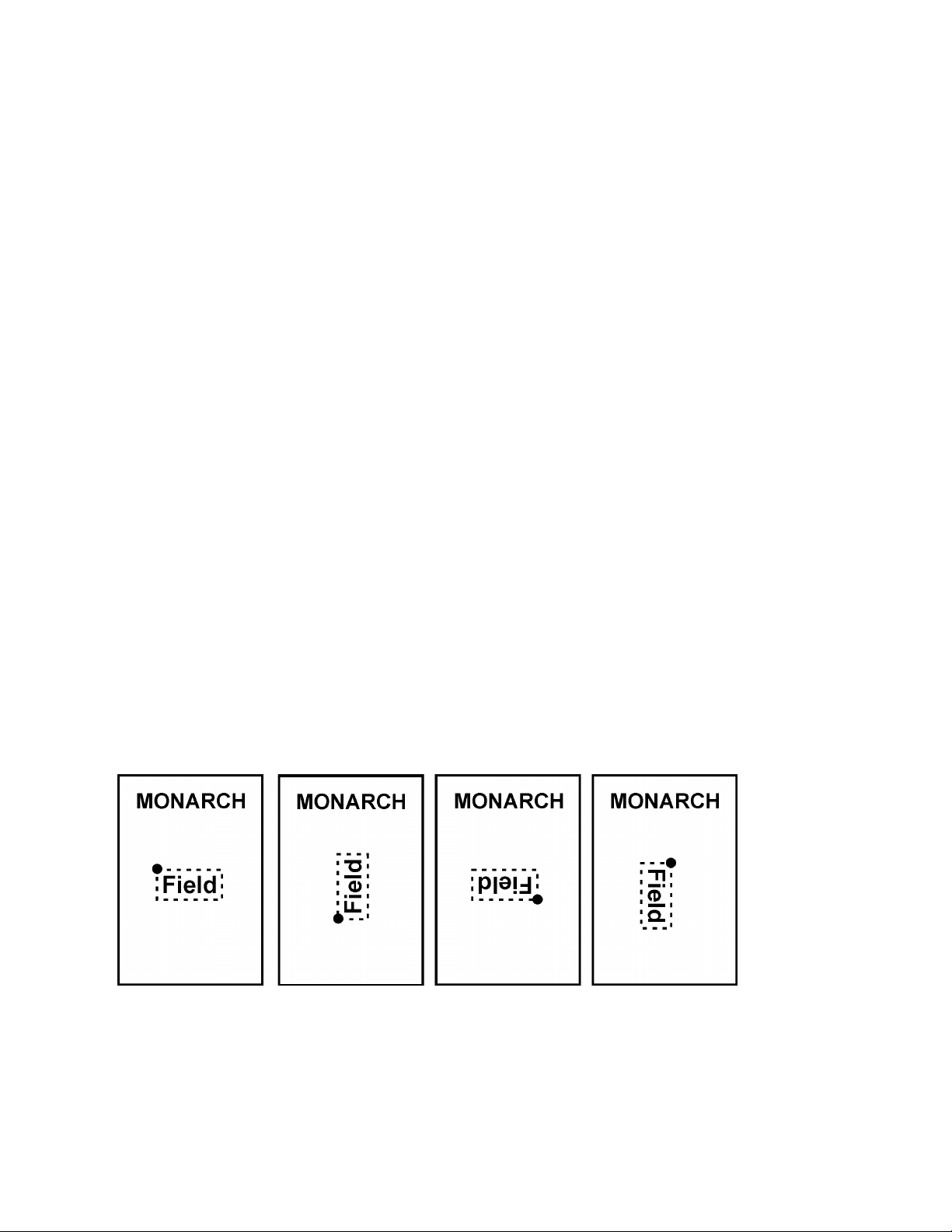
Defining the Rotation Tag (Optional)
The Rotation tag select s the rotation of the bounding box in degrees. Rotation occurs f rom the
origin point of the bounding box.
Valid values include: 0, 90, 180, or 270. The def ault is 0.
Syntax <Rotation>value</Rotation>
Example <Rotation>180</Rotation>
The printed field is rot ated 180° on the label.
Defining Field Setup XML Tags 3-3
Page 24

Defining the DrawMode Tag (Optional)
Transparent
The bounding box does not block out (or “erase”) existing f ields except where data
appears in the bounding b ox.
Opaqu
The bounding box block s out (“erases”) existing fields be low it.
XOR
The data in the bounding box appears inverted (white
Transparent Opaque
XOR
The DrawMode tag specifies the transparency of the boundi ng box.
Valid values include: Transparent, Opaque, and XOR. The default is Transparent.
e
image on black background).
Field placement in the file is an important consideration when using DrawMode. If a line f ield
is defined before the text f ield, the line field may be block ed out, depending on the te xt field’s
DrawMode. If a line field is defined aft er the text f ield, the line field is not block ed out by the
selected DrawMode.
Syntax <DrawMode>value</DrawMode>
Example <DrawMode>Opaque</DrawMode>
Sets the text field’s Dra wMode to opaque, which erases any oth er fields on the label with t he
same coordinates.
3-4 LNT Programmer’s Manual
Page 25

Defining the Font Tag (Optional)
The Font tag specifies the f ont to use for this te xt field.
Valid values include: Any UNI CODE string containing less than 256 characters. The d efault is
Arial. See “
International Font Sam ple” for a LNT file using an Asian font.
It contains the followi ng attributes: pointsizeheight, pointsizewidth, italics, wordwrap,
underline, strikethr ough, mpclstyle, interch aractergap, and weight.
Note: Italics is an a vailable attribute; however, for optimal print qualit y select a font that is
already italicized.
Syntax <Font pointsizeheight=”value” pointsizewidth=”value” italics=”value” wordwrap="value"
underline="value" strikethrough="value" intercharactergap=”value” weight=”value”
codepage=”value”>Name</Font>
pointsizeheight The height point size of the font. The default is 10.
pointsizewidth The width point size of the font. The default is 10.
If pointsizeheight and pointsizewidth are not set to the same point size, the
printed characters look tall and thin or short and thick, which allows for greater
flexibility in the appearance of the font.
Note: If you set a value for pointsizeheight and set pointsizewidth to 0, the p rinted characters
will have optimal aspect ratio of character height-to-width.
italics Boolean value describing if the text is italicized. The default is 0. Options:
0 Not Italicized
1 Italicized
wordwrap Boolean value describing if wrapping text is enabled. The default is 0. See
“
Example Text Field with Wordwrap” for more information. Options:
0 Not enabled
1 Allows word wrap.
Note: When using wordwrap, you must specify the width attribute in the <BoundingBox> tag.
Do not use wordwrap with either the underline or the strikethrough attributes.
underline Boolean value describing if the text is underlined. The default is 0. Options:
0 Not underlined
1 Underlined
Note: Do not use underline with the wordwrap attribute.
strikethrough Boolean value describing if the text appears with a line through it. The default
is 0. Options:
0 No Strikethrough
1 Text appears with a line through it
Note: Do not use strikethrough with the wordwrap attribute.
intercharactergap An integer defining the number of points between characters. The default is 0.
weight The weight (boldness) of the fon t. Options:
0 FW_DEFAULT
100 FW_THIN
200 FW_EXTRALIGHT
200 FW_ULTRALIGHT
300 FW_LIGHT
400 FW_NORMAL (default)
400 FW_REGULAR
500 FW_MEDIUM
600 FW_SEMIBOLD
600 FW_DEMIBOLD
700 FW_BOLD
800 FW_EXTRABOLD
800 FW_ULTRABOLD
900 FW_HEAVY
900 BLACK
Defining Field Setup XML Tags 3-5
Page 26

mpclstyle Boolean value describing if tilde sequences are replaced with their special
Internal Code Page
Code Page 100
character equivalents. The default is 0. See “
MPCLSTYLE” for more information. Options:
0 Do not replace tilde sequences
1 Replace tilde sequences
codepage Code page/symbol set. The default is 0. Options:
0 Internal
100 Macintosh
101 Wingdings
102 Unicode
103 BIG5 for Unicode
104 GB2312 for Unicode
105 Code page 932/SJIS/Japanese
106 Code page 936/GB2312/Simplified Chinese
107 Code page 950/BIG5/Traditional Chinese
108 KSC5601/Korean
110 Unicode UTF-8
111 UTF-8 (Input processed left-to-right)
112 UTF-8 (Input processed right-to-left)
Note: See Appendix C, “
name The name of the resident font (EFF Swiss Bold) or the font’s filename (without
the extension) for installed fonts.
The printable characters in the EFF Swiss Bold font are shown below:
Codepages” for more information.
Example Text Field with
Example <Font pointsizeheight=”10” pointsizewidth=”12” intercharactergap=”2” > Eff Swiss
Specifies the res ident font, EFF Swiss Bold with a he ight of 10 points, width of 12 points, and
an intercharactergap gap of 2 points f or this text field.
3-6 LNT Programmer’s Manual
Bold</Font>
Page 27

PRETZELS with
The text field “PRETZELS with butter and
Example <Font pointsizeheight="11" pointsizewidth="8">comic</Font>
Specifies Comic Sans MS f ont with a height of 11 points and a widt h of 8 points for this text
field.
Note: The Comic Sans MS font must be ins talled on the printer. See “
Installing Fonts” for
more information.
Example Text Field wit h Wordwrap
<TextField id= "item">
<Volatile>0</Volatile>
<BoundingBox units="Inches" x="0.35" y = "0.25" height="0" width= "1. 25" />
<Font pointsizeheight="9.0" pointsizewidth="9.0" wordwrap="1" >Arial</Font>
<VerticalJustification>Bottom</VerticalJustification>
<HorizontalJustification>Left</HorizontalJustification>
<Data>PRETZELS with butter and sea salt.</Data>
</TextField>
butter and sea salt .
sea salt.” has word-w rapping enabled. The
dotted line represents the bounding box
with a width of 1.25 inches. Arial Bold font
is used with a height and width of 9 points.
Example Text Field wit h MPCLSTYLE
<TextField id= "item">
<Volatile>0</Volatile>
<BoundingBox units="Inches" x="0.35" y = "0.25" height="0" width= "1. 25" />
<Font pointsizeheight="9.0" pointsizewidth="9.0" mpclstyle="1" codepage="100" >Arial</Font>
<VerticalJustification>Bottom</VerticalJustification>
<HorizontalJustification>Left</HorizontalJustification>
<Data>~219 35</Data>
</TextField>
The data in this field print s as € 35 since ~219 is the tilde sequence for the Euro sym bol.
Defining Field Setup XML Tags 3-7
Page 28

Defining the VerticalJustification Tag (Optional)
Top
Left
Right
The VertficalJustif ication tag describes how t ext fits vertically in the f ield.
Valid values include: Top, Bot tom, and Center. The default is Top.
Syntax <VerticalJustification>value</VerticalJustification>
Center
Bottom
Example <VerticalJustification>Bottom</VerticalJustification>
Vertically justifies th e text at the bottom of the f ield.
Defining the HorizontalJustification Tag (Optional)
The HorizontalJustific ation tag describes ho w text fits horizontally in the f ield.
Valid values include: L eft, Right, and Center. The def ault is Left.
Note: Center aligns the text based on t he Bounding Box’s width value. If the width is not
defined or set to 0, the text is cent ered based on the Bounding B ox’s x value.
Syntax <HorizontalJustification>value</HorizontalJustification>
Center
Example <HorizontalJustification>Right</HorizontalJustification>
Horizontally aligns the t ext on the right side in the f ield.
Defining the BackgroundColor Tag (Optional)
The BackgroundColor t ag sets the background color f or the field to black or white.
Valid values include: Black, White, or hex encoded RGB value in the format #RRGG BB. The
only valid hex values are #FFFFF F (white) and #000000 (black ). The default is White.
Syntax <BackgroundColor>value</BackgroundColor>
Example <BackgroundColor>Black</BackgroundColor>
Sets the background color of the field to black.
3-8 LNT Programmer’s Manual
Page 29

Defining the ForegroundColor Tag (Optional)
The ForegroundColor tag sets the text’s color in the field t o black or white.
Valid values include: Black, White, or hex encoded RGB value in the format #RRGGBB. The
only valid hex values are #FFFFF F (white) and #000000 (black ). The default is Black.
Syntax <ForegroundColor>value</ForegroundColor>
Example <ForegroundColor>White</ForegroundColor>
Sets the text’s color to white.
Defining Field Setup XML Tags 3-9
Page 30

Defining the Bar codeField (Required)
The BarcodeField tag spe cifies how the bar code field appear s on the label.
It contains the followi ng attribute: id.
Syntax <BarcodeField id=”value” >
bar code field information
</BarcodeField>
id The identifier (name) of the bar code field. Any applic ations using LNT should
reference this data. Use any 32-character maximum (UNICODE) string. Do
not use the same name for two fields or an error occurs!
Example <BarcodeField id=”UPCA” >
bar code field information
</BarcodeField>
Specifies a bar code field cal led “UPCA” in the LNT file.
Defining the Data Tag (Required)
The Data tag specifies ho w many characters are expected in t he field. It can also contain t he
fixed bar code data.
Note: If this field is Volatile, min and max are r equired attributes.
We recommend setting the min and max attributes.
Valid values include: Any Unicode string l ess than 2K characters.
It contains the followi ng attributes: min and max.
Syntax <Data min=”value” max=”value”>value</Data>
min Minimum number of characters in the field.
max Maximum number of characters in the field.
Example <Data min=”1” max=”12” />
Specifies the data leng th from 1 to 12 characters in the bar code field.
Example <Data>012345678901</Data>
Prints the fixed data 0123456789012 in the bar code f ield.
Defining the Volatile Tag (Required)
The Volatile tag specif ies whether the field’s data is s et at creation or print time. For data set
at print time, the user ent ers the data.
Valid values include: 0 (set at creation) or 1 (set at pr int time). The default is 1.
Syntax <Volatile>value</Volatile>
Example <Volatile>1</Volatile>
The data for this field is ent ered at print time.
Note: To create a fixed bar code on a labe l, set volatile to 0 and add a <Data> tag with the
fixed data for the bar code.
Example <Volatile>0</Volatile>
<Data>012345678901</Data>
Prints the fixed data 012345678901 in the specif ied bar code field (all requir ed bar code
attributes are not shown) .
3-10 LNT Programmer’s Manual
Page 31

Defining the Origin Tag (Required)
The Origin tag defines the c orner of the bar code.
It contains the followi ng attributes: units, just ification, x, and y.
Syntax <Origin units=”value” justification=”value” x=”value”
y=”value” />
units Unit of measure. Options:
Inches Inches
MM Millimeters
Pixels Pixels (default)
justification Justification of the bar code in respect
to the origin location. Options:
Left (default)
Center
Right
Note: Starting at the specified x,y coordinates, the bar code fills in
to the right with Left justification.
to the left and right with Center justification.
to the left with Right justification.
x X-Coordinate of the corner of the bar code. An integer or float (in s elected
units) that is less than the width.
y Y-Coordinate of the corner of the bar code. An integer or float (in selected
units) that is less than the height.
Example <Origin units=”Inches” justification=”Left” x=”0.05” y=”0.25” />
Defines the left corner of the bar code starting on the x axis at 0.05 and t he y axis at 0.25.
Example <Origin units=”Inches” justification=”Center” x=”0.05”
y=”0.25” />
Defines the center of the bar code starting on the x axis at 0. 05 and the y axis at 0.25.
Defining Field Setup XML Tags 3-11
Page 32

Defining the BarHeight Tag (Required)
0 Rotation 90 Rotatio n 180 Rotation 270 Rotation
The BarHeight tag defines t he bar code’s height (in selecte d units).
Valid values include: An integer or float g reater than zero and less than the < ImageHeight>
minus the <Origin> value in selected units.
It contains the followi ng attribute: units.
Syntax <BarHeight units=”value”>value</BarHeight>
units Unit of measure. Options:
Inches Inches
MM Millimeters
Pixels Pixels (default)
Example <BarHeight units=”Inches”>0.50</BarHeight>
Defines the bar code’s heig ht as 0.50 inches.
Defining the Type Tag (Required)
Defines the bar code type f or this field.
Valid values include: Any Unic ode string of less than 256 chara cters, includin g:
upca, upca+2, upca+5, upce, upce1, upce+2, upce+5, ean8, ean8+2, ean8+5, ean13, ean13+ 2,
ean13+5, i2of5, itf, code39, code93, code2 of5, codabar, nw7, msi, code12 8, code128a,
code128b, code128c, pdf417, micropdf 417, maxicode, code16, data matr ix, quick response, qr,
postnet, gs1databar, gs1, or rss.
Syntax <Type>value</Type>
Example <Type>upca</Type>
Defines the bar code type as upca.
Defining the Orientation Tag (Optional)
The Orientation tag selects t he rotation of the bar code in deg rees.
Valid values include: 0 , 90, 180, and 270. The default is 0.
Syntax <Orientation>value</Orientation>
Example <Orientation>90</Orientation>
Rotates the bar code 90° o n the label.
Defining the Options Tag (Optional)
The Options tag defines an y options supported by the bar code’s <type>. For m ore information
about each bar code’s support ed options, see Chapter 4, “
information.
3-12 LNT Programmer’s Manual
Defining Bar Code Option s” for more
Page 33

Defining the LineField Ta g (Required)
The LineField tag def ines a li ne. Use lines to form borders and mark out original prices.
Note: The solid black print can n ot exceed 30 percent of any gi ven square inch of the label.
It contains the follo wing attribute: id.
Syntax <LineField id=”value” >
line field information
</LineField>
id The identifier (name) of the line field. Any applications using LNT should
reference this data. Use any 32-character ma ximum (UNIC ODE) string. Do
not use the same name for two fields or an error
occurs!
Example <LineField id=”Border1” >
line field information
</LineField>
Specifies a line f ield called “Border1” in th e LNT file.
Defining the Offset1 Tag (Required)
The Offset1 tag defines the f irst point of a line segment.
It contains the followi ng attributes: units, x, and y.
Syntax <Offset1 units=”value” x=”value” y=”value” />
units Unit of measure. Options:
Inches Inches
MM Millimeters
Pixels Pixels (default)
x An integer or float (in s elected units) that is less than the <ImageWidth>.
y An integer or float (in sel ected units) that is less than the <ImageHeight>.
Example <Offset1 units=”Inches” x=”0.25” y=”0.15” />
Sets the starting point for the line on the x axis at 0.25 and the y axis at 0.15.
Defining the Offset2 Tag (Required)
The Offset2 tag defines the endi ng point of a line segment.
It contains the followi ng attributes: units, x, and y.
To create horizontal lines , keep the y values the same and onl y change the x values.
To create vertical lines , keep the x values the same and onl y change the y values.
Syntax <Offset2 units=”value” x=”value” y=”value” />
units Unit of measure. Options:
Inches Inches
MM Millimeters
Pixels Pixels (default)
x An integer or float (in selected units) that is less than the <ImageWidth>.
y An integer or float (in selected units) that is less than the <ImageHeight>.
Example <Offset2 units=”Inches” x=”0.25” y=”0.75” />
Sets the ending point f or the line on the x axis at 0.25 and the y axis at 0.75.
Defining Field Setup XML Tags 3-13
Page 34

Example <Offset1 units=”Inches” x=”0.25” y=”0.15” />
<Offset2 units=”Inches” x=”0.75” y=”0.15” />
Creates a 0.5-inch horizo ntal line beginning at 0.25 inches and ending at 0.75 inches on the
y-axis at 0.15 inches.
Defining the Thickness Tag (Required)
The Thickness tag defines t he line thickness.
Valid values include: An int eger or float (in selected unit s).
It contains the followi ng attribute: units.
Syntax <Thickness units=”value”>value</Thickness>
units Unit of measure. Options:
Inches Inches
MM Millimeters
Pixels Pixels (default)
Example <Thickness units=”Inches”>0.10</Thickness>
Defines a line 0.10 inches t hick.
3-14 LNT Programmer’s Manual
Page 35

Defining the BoxF ield Tag (Required)
The BoxField tag def ines a box. Use boxes to form bor ders or highlight items of int erest.
Note: The solid black print can n ot exceed 30 percent of any gi ven square inch of the label.
It contains the followi ng attribute: id.
Syntax <BoxField id=”value” >
box field information
</BoxField>
id The identifier (name) of the line field. Any
applications using LNT should reference this data.
Use any 32-character maximum (UNICODE) st ring.
Do not use the same name for two fields or an error
occurs!
Example <BoxField id=”Box1” >
box field information
</BoxField>
Specifies a box field called “ Box1” in the LNT file.
Defining the Box Tag (Required)
The Box tag specifies the coordinates for the box field on th e label.
It contains the followi ng attributes: units, x, y, heig ht, and width.
Syntax <Box units=”value” x=”value” y=”value” height=”value” width=”value” />
units Unit of measure. Options:
Inches Inches
MM Millimeters
Pixels Pixels (default)
x X-Coordinate of the corner of the bounding box. Use an integer or float (in
selected units) that is less than the width.
y Y-Coordinate of the corner of the bounding box. Use an integer or float (in
selected units) that is less than the height.
height The height (in selected units) of the print area. Use an integer or float value
greater than zero and less than the image height.
width The width (in selected units) of the print area. Use an integer or float value
greater than zero and less than the image width.
Example <Box units=”Inches” x=”0.25” y=”0.15” height=”0.50”
width=”0.50” />
Defines a box that begins on t he x axis at 0.25 and the y axis at 0. 15; the box’s height and
width are 0.50 inches.
Defining Field Setup XML Tags 3-15
Page 36

Defining the Line Thickness Tag (Required)
The LineThickness tag def ines the thickness of the box’s l ines.
Valid values include: An int eger or float (in selected unit s).
It contains the followi ng attribute: units.
Syntax <LineThickness units=”value”>value</LineThickness>
units Unit of measure. Options:
Inches Inches
MM Millimeters
Pixels Pixels (default)
Example <LineThickness units=”Inches”>0.05</LineThickness>
Defines the box’s line s as 0.05 inches thick.
Defining the DrawMode Tag (Optional)
The DrawMode tag specifies the transparency of the boundi ng box.
Valid values include: Transparent, Opaque, and XOR. T he default is Transparent.
Transparent The bounding box does not block out (or “erase”) existing f ields except
where data appears in the bound ing box.
Opaque The bounding box block s out (“erases”) existing fields be low it.
XOR The data in the bounding box appears inverted (white image on a black
background).
Syntax <DrawMode>value</DrawMode>
Example <DrawMode>Opaque</DrawMode>
Sets the box field’s DrawMode to o paque, which erases any other fields on the label with the
same coordinates.
Defining the LineColor Tag (Optional)
The LineColor tag sets t he line’s color to black or white.
Valid values include: Black, Whit e, or hex encoded RGB value in the f ormat #RRGGBB. The
only valid hex values are #FFFFFF (white) and #000000 ( black). The default is Black.
Syntax <LineColor>value</LineColor>
Example <LineColor>Black</LineColor>
Sets the line’s color to black .
Defining the FillColor Tag (Optional)
The FillColor tag sets t he fill color for the box to black or white.
Valid values include: Black , White, or hex encoded RGB val ue in the format #RRGGBB. T he
only valid hex values are #FFFFFF (white) and #000000 ( black). The default is Black.
Syntax <FillColor>value</FillColor>
Example <FillColor>Black</FillColor>
Sets the box’s fill color t o black.
3-16 LNT Programmer’s Manual
Page 37

Defining an Elli pseField (Required)
The EllipseField tag def ines a circle or an oval. Use ellipses to for m borders or highlight it ems
of interest.
It contains the followi ng attribute: id.
Syntax <EllipseField id=”value” >
ellipse field information
</EllipseField>
id The identifier (name) of the field. Any
applications using LNT should reference this
data. Use any 32-character maximum
(UNICODE) string. Do not use the same name
for two fields or an error occurs!
Example <EllipseField id=”Circle1” >
ellipse field information
</EllipseField>
Specifies an ellipse f ield called “Circle1” i n the LNT file.
Defining the BoundingBox Tag (Required)
The BoundingBox tag defines the area on the label where the ell ipse field appears. Each f ield
on a label must fit inside a bou nding box.
It contains the followi ng attributes: units, x, y, heig ht, and width.
Syntax <BoundingBox units=”value” x=”value” y=”value” height=”value” width=”value” />
units Unit of measure. Options:
Inches Inches
MM Millimeters
Pixels Pixels (default)
x X-Coordinate of the Origin corner of the bounding box. Use an integer o r float
(in selected units) that is less than the width.
y Y-Coordinate of the Origin corner of the bounding bo x. Use an integer or float
(in selected units) that is less than the height.
height The height (in selected units) of the print area. Use an integer or float
value tha t is less than the image height. Use zero to let the printer determine
the height.
width The width (in selected units) of the print area. Use an integer or float value
that is less than the image width. Use zero to let the printer determine the
width.
Example <BoundingBox units=”Inches” x=”0.70” y=”0.30” height=”0.20” width=”0.80” />
Sets the coordinates f or the ellipse field’s bounding box and specifies the height as 0.20
inches and the width as 0. 80 inches.
Defining Field Setup XML Tags 3-17
Page 38

Defining the Line Thickness Tag (Required)
The Line Thickness t ag defines the thickness of the ellipses’ lin es.
Valid values include: An int eger or float (in selected unit s).
It contains the followi ng attribute: units.
Syntax <LineThickness units=”value”>value</LineThickness>
units Unit of measure. Options:
Inches Inches
MM Millimeters
Pixels Pixels (default)
Example <LineThickness units=”Inches”>0.10</LineThickness>
Defines the ellipses ’ lines as 0.10 inches thick.
Defining the DrawMode Tag (Optional)
The DrawMode tag specifies the transparency of the boundi ng box.
Valid values include: Transparent, O paque, and XOR. The default is Transparent.
Transparent The bounding box does not block out (or “erase”) existing f ields except
where data appears in the bound ing box.
Opaque The bounding box blocks out (“erases”) existing fields belo w it.
XOR The data in the bounding box appears inverted (white image on a black
background).
Syntax <DrawMode>value</DrawMode>
Example <DrawMode>Opaque</DrawMode>
Sets the box field’s DrawMo de to opaque, which erases any oth er fields on the label with t he
same coordinates.
Defining the LineColor Tag (Optional)
The LineColor tag sets the line’s co lor to black or white.
Valid values include: Black , White, or hex encoded RGB val ue in the format #RRGGBB. T he
only valid hex values are #FFFFF F (white) and #000000 (black ). The default is Black.
Syntax <LineColor>value</LineColor>
Example <LineColor>Black</LineColor>
Sets the line’s color to black .
Defining the FillColor Tag (Optional)
The FillColor tag sets t he fill color for the ellipse to b lack or white.
Valid values include: Black, White, or hex encoded RGB value in the format #RRGGBB. The
only valid hex values are #FFFFF F (white) and #000000 (black ). The default is Black.
Syntax <FillColor>value</FillColor>
Example <FillColor>Black</FillColor>
Sets the ellipse’s fill color to black.
3-18 LNT Programmer’s Manual
Page 39

Defining a Gra phicField (Required)
The GraphicField tag de fines a graphic. T he following graphic file types ar e supported: BMP,
GIF, JPG, and PNG.
It contains the followi ng attribute: id.
Syntax <GraphicField id=”value” >
graphic field information
</GraphicField>
id The identifier (name) of the field. Any
applications using LNT should reference this
data. Use any 32-character maximum
(UNICODE) string. Do not use the same name
for two fields or an error occurs!
Example <GraphicField id=”Logo1” >
graphic field information
</GraphicField>
Specifies a graphic field called “Logo1” in the LNT file.
Defining the Volatile Tag (Required)
The Volatile tag specif ies whether the field’s data is se t at creation or print time. For data set
at print time, the user ent ers the data.
Valid values include: 0 (set at creation) or 1 (set at pr int time). The default is 1.
Syntax <Volatile>value</Volatile>
Example <Volatile>1</Volatile>
The data for this field is ent ered at print time.
Defining the BoundingBox Tag (Required)
The BoundingBox tag defines the area on the label where the f ield appears. Each field on a
label must fit inside a bounding box.
It contains the followi ng attributes: units, x, y, heig ht, and width.
Syntax <BoundingBox units=”value” x=”value” y=”value” height=”value” width=”value” />
units Unit of measure. Options:
Inches Inches
MM Millimeters
Pixels Pixels (default)
x X-Coordinate of the Origin corner of the bounding box. Use an integer o r float
(in selected units) that is less than the width.
y Y-Coordinate of the Origin corner of the bounding bo x. Use an integer o r float
(in selected units) that is less than the height.
height The height (in selected units) of the print area. Use an integer or float
value tha t is less than the image height. Use zero to let the printer determine
the height.
width The width (in selected units) of the print area. Use an integer or float value
that is less than the image width. Use zero to let the printer determine the
width.
Example <BoundingBox units=”Inches” x=”0.70” y=”0.30” height=”0.20” width=”0.80” />
Sets the coordinates f or the graphic field’s bounding bo x and specifies the height as 0.20
inches and the width as 0. 80 inches.
Defining Field Setup XML Tags 3-19
Page 40

Defining the Data Tag (Required)
The Data tag contains the f ilename of the graphic. T he following graphic file types ar e
supported: BMP, GIF, JPG , and PNG. Save the graphic to the Temp\Install folder on the
Mobile Device (printer) .
Note: Check the \Windows\ Resources\Images folder on the Mobile Device (printer) to m ake
sure the file installed c orrectly. Do not save f iles directly to this folder.
Valid values inc lude: Any Unicode string less than 2K characters.
Syntax <Data>value</Data>
Example <Data>OurLogo</Data>
Prints the graphic named O urLogo.bmp in the graphic field.
Defining the DrawMode Tag (Optional)
The DrawMode tag specifies the transparency of the boundi ng box.
Valid values include: Transparent, O paque, and XOR. The default is Transparent.
Transparent The bounding box does not block out (or “erase”) existing f ields except
where data appears in the bound ing box.
Opaque The bounding box blocks out (“erases”) existing fields belo w it.
XOR The data in the bounding box appears inverted (white image on a black
background).
Syntax <DrawMode>value</DrawMode>
Example <DrawMode>Opaque</DrawMode>
Sets the graphic f ield’s DrawMode to opaque, which eras es any other fields on the labe l with
the same coordinates.
Defining the VerticalJustification Tag (Optional)
The VertficalJustif ication tag describes how t ext fits vertically in the f ield.
Valid values include: T op, Bottom, and Center. The def ault is Top.
Syntax <VerticalJustification>value</VerticalJustification>
Syntax <VerticalJustification>Bottom</VerticalJustification>
Vertically justifies the text at the bottom of the f ield.
Defining the HorizontalJustification Tag (Optional)
The HorizontalJustif ication tag describes ho w text fits horizontally in the f ield.
Valid values include: L eft, Right, and Center. The def ault is Left.
Syntax <HorizontalJustification>value</HorizontalJustification>
Example <HorizontalJustification>Right</HorizontalJustification>
Horizontally aligns the t ext on the right side of the f ield.
3-20 LNT Programmer’s Manual
Page 41

Bar Code
Scan
Print
Bar Code
Scan
Print
4
DEFINING BAR CODE OPTIONS
This chapter defines the uniq ue set of bar code options f or each bar code. Bar codes are
separated into one-d imensional and two-dimens ional categories.
1D Bar Codes 2D Bar Codes
Codabar
Code 16K
Code 39
Code 93
Code 128
Interleaved 2of5
MSI
UPCA, UPC E, EAN
Data Matrix
GS1 DataBar
MaxiCode
Micro PDF41 7
PDF417
POSTNET
Quick Resp onse
Scannable Bar Codes vs. Printable Bar Codes
Use the following table t o see which bar codes the printer c an scan and print:
Codabar √ √ I2of5 √ √
Code 16 √ I2 of 5 with Barrier Bar √ √
Code 39 (no check digit) √ √ MaxiCode √* √
Code 39 (MOD 43 check digit) √ √ MicroPDF417 √* √
Code 93 √ √ MSI √ √
Code 128 √ √ PDF417 √ * √
Data Matrix √* √ Postnet √
EAN 8 √ √ Quick Response √ * √
EAN 8 +2 √ √ UPCA √ √
EAN 8 +5 √ √ UPCA +2 √ √
EAN 13 √ √ UPCA +5 √ √
EAN 13 +2 √ √ UPCA & Price CD √ √
EAN 13 +5 √ √ UPCE √ √
EAN 13 & Pr ice CD √ √ UPCE +2 √ √
GS1 DataBar / RSS √ * √ UPCE +5 √ √
The bar code options inc lude, but are not limited to:
♦ Human readable
♦ Density
♦ Characters per inch
♦ Narrow width
♦ Wide width
♦ Narrow space/ wide space.
The <Options> t ag defines any options support ed by the bar code’s type. See the f ollowing
sections to define the O ptions tag, based on your bar code ty pe.
* Requires t he 6057 optional 2D scanner; the 2D scanner is standard on the 6140.
Defining Bar Code Options 4-1
Page 42

Defining the Codabar Options Tag (Optional)
Density
Density
Narrow Element Width
Narrow to Wide
2
2.1
8 /39.4
1:3.0
3
3.0
6 / 29.6
1:2.5
4
4.6
4 / 19.7
1:2.5
5
5.1
4 / 19.7
1:2.0
7
8.4
2 / 9.9
1:3.0
8
9.2
2 / 9.9
1:2.5
9
10.1
2 / 9.9
1:2.0
narrowbar
Use the density table above . Using a non-standard value may produce
Density
Density
Narrow Element Width
20
3.5/7.0
5/24.6
4
4.4/8.7
4/19.7
6
5.8/11.7
3/14.8
8
8.7/17.5
2/9.9
Use the Options tag to def ine Codabar-specific inf ormation.
Valid values include: a 32-bit unsigned d ecimal number.
It contains the followi ng attributes: density, narrowbar, widebar, narrowspace, widespace, and
interchargap.
Syntax <Options density=”value” narrowbar=”value” widebar=”value” narrowspace=”value”
widespace=”value” interchargap=”value” />
density Bar code density. Options: 2 to 9 as shown below. The default is 8.
Selector
(% or cpi)
in Dots/Mils
Ratio
widebar
narrow space
wide space
unreadable bar codes. Define in Pixels.
interchargap The inter character gap between two character representations. This is usually
defined the same as narrowspace. Define in Pixels.
Example <Options density=”4” interchargap=”1” />
Creates a Codabar bar code with a density of 4 and an intercha racter gap of 1.
Defining the Code 16K Options Tag (Optional)
Use the Options tag to define Code 16 K-specific inform ation.
Valid values include: a 32-bit unsigned d ecimal number.
It contains the followi ng attributes: density and subbar height.
Syntax <Options density=”value” subbarheight=”value” />
Example <Options density=”6” />
Creates a Code 16K bar code wit h a density of 6 and does not specif y a subbarheight.
4-2 LNT Programmer’s Manual
density Bar code density. Options: 4, 6, 8, or 20 as shown below. The default is 8.
Selector
subbarheight The height of each row of bars. Define in Pixels.
(% or cpi)
in Dots/mils
Page 43

Density
Density
Narrow Element Width
Narrow to Wide
1
1.4
10 / 49.3
1:2.5
2
1.7
8 / 39.4
1:2.5
3
3.5
4 / 19.7
1:2.5
4
4.2
3 / 14.8
1:3.0
6
6.3
2 / 9.9
1:3.0
Use the density table above . Using a non-standard value may produce
Defining the Code 39 Options Tag (Optional)
Use the Options tag to define Code 39-specific infor mation.
Valid values include: a 32-bit unsigned d ecimal number.
It contains the followi ng attributes: density, nar rowbar, widebar, narrowspace, widespace,
interchargap, and mod43cd.
Syntax <Options density=”value” narrowbar=”value” widebar=”value” narrowspace=”value”
widespace=”value” interchargap=”value” mod43cd=”value” />
density Bar code density. Options: 1 to 7, 11, 12, and 20 shown below. The default is
7.
Selector
7 7.0 2 / 9.9 1:2.5
11 3.9 4 / 19.7 1:2.0
12 12.7 1 / 4.9 1:2.0
20 3.0 5 / 24.6 1:2.2
(% or cpi)
in Dots/Mils
Ratio
narrowbar
widebar
narrow space
wide space
unreadable bar codes. Defi ne in Pixels.
interchargap The inter character gap between two character representations. This is usually
defined the same as narrowspace. Define in Pixels.
mod43cd Enable Mod43 check digit? Options:
0 Disable
1 Enable (Extended Code 39)
Example <Options density=”6” mod43cd=”1” />
Creates a Code 39 bar code with a den sity of 6 and the bar code pr ints as an Extended Code
39 bar code.
Defining Bar Code Options 4-3
Page 44

Defining the Code 93 Options Tag (Optional)
Density
Density
Narrow Element Width
3
3.7
6 / 29.6
5
5.6
4 / 19.7
7
7.5
3 / 14.8
Density
Density
Narrow Element Width
20
3.5/7.0
5/24.6
4
4.4/8.7
4/19.7
6
5.8/11.7
3/14.8
8
8.7/17.5
2/9.9
Use the Options tag to define Code 93-specif ic information.
Valid values include: a 32-bit unsigned d ecimal number.
It contains the followi ng attributes: density and nar rowbar.
Syntax <Options density=”value” and narrowbar=”value” />
density Bar code density. Options: 3, 4, 5, 7, and 10 as shown below. The default is
7
Selector
4 4.5 5 / 24.6
10 11.2 2 / 9 .9
(% or cpi)
in Dots/Mils
narrowbar Use the density table above. Using a non-standard value may produce
unreadable bar codes. Define in Pixels.
Example <Options density=”5” />
Creates a Code 93 bar code with a den sity of 5 and does not specif y a narrow bar value.
Defining the Code 128 Options Tag (Optional)
Use the Options tag to define Code 12 8-specific inform ation.
Valid values include: a 32-bit unsigned d ecimal number.
It contains the followi ng attributes: density and nar rowbar.
Syntax <Options density=”value” and narrowbar=”value” />
density Bar code density. Options: 4, 6, 8, and 20 as shown below. The default is 8.
Example <Options density=”6” />
Creates a Code 128 bar code with a density of 6 and does not specify a narr ow bar value.
4-4 LNT Programmer’s Manual
Selector
narrowbar Use the density table above. Using a non-standard value may produce
unreadable bar codes. Define in Pixels.
(% or cpi)
in Dots/mils
Page 45

Density
Density
Narrow Element Width
Narrow to Wide
1
1.1
21 / 103.4
1:3.0
2
2.1
12 / 59.1
1:2.5
3
3.2
7 / 34.5
1:3.0
4
4.2
6 / 29.6
1:2.5
5
5.6
4 / 19.7
1:3.0
6
6.3
4 / 19.7
1:2.5
7
7.5
3 / 14.8
1:3.0
8
8.8
3 / 14.8
1:2.3
9
9.6
3 / 14.8
1:2.0
10
11.2
2 / 9.9
1:3.0
11
11.0
2 / 9.9
1:3.0
12
12.7
2 / 9.9
1:2.5
13
14.5
2 / 9.9
1:2.0
Defining the Interleaved 2of5 Options Tag (Optional)
Use the Options tag to def ine Interleaved 2of5-specif ic information.
Valid values include: a 32-bit unsigned d ecimal number.
It contains the followi ng attributes: density, narrowbar, widebar, and barrierbar .
Syntax <Options density=”value” narrowbar=”value” widebar=”value” barrierbar=”value” />
density Bar code density. Options: 1 to 13 as shown below. The default is 12.
Selector
(% or cpi)
in Dots/Mils
Ratio
narrowbar
widebar
Use the density table above . Using a non-standard value may produce
unreadable bar codes. Defi ne in Pixels.
barrierbar Print a barrier bar (border lines at the top and bottom of the bar code). The
default is disabled (does not print a barrier bar). Options:
0 Disable
1 Enable (print a barrier bar)
Example <Options density=”8” barrierbar=”1” />
Creates an I 2of5 bar code with a dens ity of 8 and prints a barrier bar.
Defining Bar Code Options 4-5
Page 46

Defining the MSI Options Tag (Optional)
Density
Density
Narrow Element Width
Narrow to Wide
4
4.2
4 / 19.7
1:2.0
5
5.6
3 / 14.8
1:2.0
7
7.2
2 / 9.9 (Default value)
1:2.5
narrowbar
Use the density table above . Using a non-standard value may produce
Density
Density
Narrow Element Width
2
76%
2 / 9.9
4
114%
3 / 14.8
Use the Options tag to define MSI-spec ific information.
Valid values include: a 32-bit unsigned d ecimal number.
It contains the followi ng attributes: density, narrowbar, and widebar.
Syntax <Options density=”value” narrowbar=”value” widebar=”value” />
density Bar c ode density. Options: 4, 5, or 7 as shown below. The default is 7.
Selector
(% or cpi)
in Dots/Mils
Ratio
widebar
unreadable bar codes. Defi ne in Pixels.
Example <Options density=”4” />
Creates an MSI bar code with a dens ity of 4 and does not specify a narr ow or wide bar value.
Defining the UPCA/UPCE/EAN Options Tag (Optional)
Use the Options tag to define UPC A/UPCE/EAN-specific inf ormation. Applies to UPCA +2/+ 5
Price CD, UPCE +2/+5, EAN8 +2/+5, EAN13 +2/+5 Price CD bar codes.
Valid values include: a 32-bit unsigned d ecimal number.
It contains the followi ng attributes: density and hum anreadable.
Syntax <Options density=”value” and humanreadable=”value” />
density Bar code density. Options: 2 or 4 as shown below. The default is 2.
Selector
(% or cpi)
in Dots/mils
humanreadable Appearance of human readable text with the bar code. The default is 0.
Options:
0 No human readable text, print bar code only.
1 Print data, number system, and check digit.
2 Print data only.
3 Print data and the number system.
4 Print data and check digit.
Example <Options density=”4” humanreadable=”4”/>
Creates a UPCA bar code with a dens ity of 4 (114%) and prints data an d the check digit along
with the bar code.
4-6 LNT Programmer’s Manual
Page 47

Density Selector
Size Row x Column
0
bar code size is autom atically determined by the data.
1
10 x 10
2
12 x 12
3
14 x 14
4
16 x 16
5
18 x 18
6
20 x 20
7
22 x 22
8
24 x 24
17
72 x 72
18
80 x 80
19
88 x 88
20
96 x 96
21
104 x 104
22
120 x 120
23
132 x 132
24
144 x 144
Defining the Data Matrix Options Tag (Optional)
Use the Options tag to define Dat a Matrix-specific infor mation.
Valid values include: a 32-bit unsigned d ecimal number.
It contains the followi ng attribute: density.
Syntax <Options density=”value” />
density Bar code density. Options: 0 to 24 as shown below. The default is 0.
9 26 x 26
10 32 x 32
11 36 x 36
12 40 x 40
13 44 x 44
14 48 x 48
15 52 x 52
16 64 x 64
Example <Options density=”4” />
Creates a Data Matrix bar c ode with a size of 14 rows by 14 colum ns.
Defining Bar Code Options 4-7
Page 48

Defining the GS1 DataBar Options Tag (Optional)
Density Selector
Narrow Element Width in Dots/mils
2
2 / 9.9
3
3 / 14.8
4
4 / 19.7
5
5 / 24.6
6
6 / 29.6
7
7 / 34.5
8
8 / 39.4
Use the Options tag to define G S1 DataBar-specific infor mation.
Valid values include: a 32-bit unsigned d ecimal number.
It contains the followi ng attributes: density, type, sepheight, and segment width.
Syntax <Options density=”value” type=”value” sepheight=”value” segmentwidth=”value” />
density Bar code density. Options: 2 to 8 as shown below. The default is 2.
type Selects the type of GS1 DataBar bar code. The default is 1. Options:
1 GS1 DataBar 14
2 GS1 DataBar 14 Truncated
3 GS1 DataBar 14 Stacked
4 GS1 DataBar 14 Stacked Omni-directional
5 GS1 DataBar Limited
6 GS1 DataBar Expanded
7 UPCA
8 UPCE
9 EAN13
10 EAN8
11 UCC/EAN12 8 and CC A/B
12 UCC/EAN12 8 and CC C
sepheight The height of the separator between the linear barcode and the 2D bar code.
The default is 1. The value is either 1 or 2.
segmentwidth The width of the individual segments for bar code <types> 1 to 6 above. The
default is 22. The range is even numbers between 2 and 22.
Example <Options density=”4” type=”3” segmentwidth=”8” />
Creates a GS1 DataBar 14 Stack ed bar code with a density of 4 and sets the segment width to
8.
4-8 LNT Programmer’s Manual
Page 49

Mode
Name
Description
0
Obsolete
Superceded by modes 2 an d 3.
2
Structured Carrier
Structured shipping data, with a numeric
3
Structured Carrier
Structured shipping data, with a numeric
4
Standard
Standard text mode.
5
Full EEC
Standard text mode with e nhanced error
6
Reader Program
Data is designed to progra m the
Defining the MaxiCode Options Tag (Optional)
Use the Options tag to define MaxiCode-specific information.
Valid values include: a 32-bit unsigned d ecimal number.
It contains the followi ng attribute: mode.
Syntax <Options mode=”value” />
mode Select the MaxiCode mode. The default is 8. Options:
Message
Message
8 Auto-detect Auto-detect between modes 0, 2, and 3.
postal code.
postal code.
correction.
scanner/barcode reader.
To enter data for Modes 2 or 3, use the <Data> tag.
Defining the Data Tag (Required)
The Data tag contains the dat a for MaxiCode Mode 2 or Mode 3 bar codes .
Valid values include: Any Unicode string less than 2K character s.
It contains the followi ng attributes: Year, PostalCode, CountryCode, ServiceC lass,
TrackingNumber, Or iginCarrier, ShipperNumber, DayOfPickup, ShipmentID, Pack ageCount,
Weight, AddressValidat ion, StreetAddress, City, and St ate.
Note: These attributes are case sens itive.
Syntax <Data Year=”value” PostalCode=”value” CountryCode=”value” ServiceClass=”value”
TrackingNumber=”value” OriginCarrier=”value” ShipperNumber=”value”
DayOfPickup=”value” ShipmentID=”value” PackageCount=”value” Weight=”value”
AddressValidation=”value” StreetAddress=”value” City=”value” State=”value” />
Year Two digit year identifier. The default is 11.
PostalCode Zip or postal code, maximum of nine characters. If this field is numeric, use
Mode 2; otherwise, use Mode 3. The default is “ “.
CountryCode Three digit ISO country code. The default is “ “.
ServiceClass Three digit class of service code. The default is “ “.
TrackingNumber Package tracking number. The default is “ “.
OriginCarrier Origin carrier SCAC. The default is “ “.
ShipperNumber UPS shipper number. The default is “ “.
DayOfPickup J ulian day of pickup. The default is “ “.
ShipmentID The shipment identifier. The default is “ “.
PackageCount The count and identifier of this package in this format: 1/1, 2/5, etc. The
default is “ “.
Weight Package weight. The default is “ “.
AddressValidation Peform address validation? The default is “ “. Options:
Defining Bar Code Options 4-9
Page 50

Y Yes
N No
StreetAddress Street address. The default is “ “.
City City name. The default is “ “.
State Two character state identifier The default is “ “.
Example <Options mode=”3” />
<Data PostalCode="068100000" CountryCode="840" ServiceClass="001"
TrackingNumber="1Z12345675" OriginCarrier="UPSN" ShipperNumber="12345E"
DayOfPickup="089" ShipmentID="" PackageCount="1/1" Weight="10"
AddressValidation="Y" State="CT" />
Creates a MaxiCode Mode 3 bar cod e.
Additionally, MPCLII (Monarch® Printer Contr ol Language) batch data f or a MaxiCode bar code
can be included in the <Data> tag. Sample MPCLII MaxiCod e batch data is shown below:
1,"[)>~030" |
C,"01~02996" |
C,"068100000~029" |
C,"840~029" |
C,"001~029" |
C,"1Z12345675~029" |
C,"UPSN~029" |
C,"12345E~029" |
C,"089~029" |
C,"~029" |
C,"1/1~029" |
C,"10~029" |
C,"Y~029" |
C,"~029" |
C,"~029" |
C,"CT~030" |
C,"~004" | }
The LNT file with the <Data> tag is shown below:
Example <Data>”[)>~03001~02996068100000~029840~029001~0291Z12345675
~029UPSN~02912345E~029089~029~0291/1~02910~029Y~029~029~029CT~ 030~004”
</Data>
Note: MPCLII continuation f ields are not used in LNT.
4-10 LNT Programmer’s Manual
Page 51

Density
Element Width
Row Height
Aspect Ratio
1
2 / 9.8
2 / 9.8
1:1
Defining the Micro PDF417 Options Tag (Optional)
Use the Options tag to define Micro PDF417-specific info rmation.
Valid values include: a 32-bit unsigned d ecimal number.
It contains the followi ng attributes: density, rows, and columns.
Syntax <Options density=”value” rows=”value” columns=”value” />
density Bar code density. If a density is not selected, the default is set to the smallest
size that fits the data. Options: 1 to 9 as shown below.
Selector
2 2 / 9.8 4 / 19.7 1:2
3 2 / 9 .8 6 / 29.6 1:3
4 3 / 1 4.8 3 / 14.8 1:1
5 3 / 1 4.8 6 / 29.6 1:2
6 3 / 1 4.8 9 / 44.3 1:3
7 4 / 1 9.7 4 / 19.7 1:1
8 4 / 1 9.7 8 / 39.4 1:2
9 4 / 1 9.7 12 / 59.1 1:3
in Dots/Mils
in Dots/Mils
rows The number of rows can be set to change the shape of the bar code.
columns The number of columns can be set to change the shape of the bar code.
Example <Options density=”3” rows=”5” columns=”6” />
Creates a Micro PDF417 bar code us ing a density of 3, sets the number of rows to 5 and the
number of columns to 6.
Defining Bar Code Options 4-11
Page 52

Defining the PDF417 Options Tag (Optional)
Density
Element Width
Row Height
Aspect Ratio
1
2 / 9.8
2 / 9.8
1:1 2 2 / 9.8
4 / 19.7
1:2 3 2 / 9.8
6 / 29.6
1:3 4 3 / 14.8
3 / 14.8
1:1 5 3 / 14.8
6 / 29.6
1:2 6 3 / 14.8
9 / 44.3
1:3 7 4 / 19.7
4 / 19.7
1:1 8 4 / 19.7
8 / 39.4
1:2 9 4 / 19.7
12 / 59.1
1:3
Density
Density
Narrow Element Width
Narrow to Wide
Data Length
24/118.2
10/49.3
4/19.7 (5 dot gap)
Use the Options tag to define PDF4 17-specific inform ation.
Valid values include: a 32-bit unsigned d ecimal number.
It contains the followi ng attributes: density, security, compact, rows, and colum ns.
Syntax <Options density=”value” security=”value” compact=”value” rows=”value”
columns=”value” />
density Bar code density. If a density is not selected, the default is set to the smallest
size that fits the data. Options: 1 to 9 as shown below.
Selector
in Dots/Mils
in Dots/Mils
security Sets the security level of the bar code. Higher security levels add data to a
bar code, improving scan reliability. Some damaged bar codes may still be
scannable if the security l evel is high enough. Options: 0 to 8. The default is
0.
compact Print the bar code in Compact mode. Compact mode omits the right line
number codeword and reduces the stop pattern to a single bar. Options:
0 Prints in standard mode.
1 Prints in Compact mode.
rows The number of rows can be set to change the shape of the bar code.
columns The number of columns can be set to change the shape of the bar code.
Example <Options density=”3” security=”4” />
Creates a PDF417 bar code using a d ensity of 3 and a security level of 4.
Defining Data for POSTNET (Optional)
The Data tag contains the dat a for the POSTNET bar code.
Valid values include: Any Unicode string less than 2K character s.
Syntax <Data>”string”</Data>
Example <Data>”28028”</Data>
Prints the data 28028 in a POST NET bar code.
4-12 LNT Programmer’s Manual
Selector
0 (fixed at
4.3 cpi)
(% or cpi)
in Dots/Mils
Ratio
0, 5, 6, 9, 10, 11 or
12
Page 53

Defining the Quick Response Options Tag (Optional)
Use the Options tag to define Q uick Response-specific inf ormation. The Quick Respo nse bar
code is identified by either qr or quickresponse.
Quick Response (QR Code) is a t wo-dime nsional bar code, which is made u p of square
modules arranged in an overall sq uare pattern. A unique f inder pattern is located at t hree
corners of the symbol. Four levels of error correction are a vailable, along with a wide range of
symbol sizes.
♦ Model 1 is the original specification.
♦ Model 2 is an enhanced form t hat includes additional feat ures.
The maximum number of char acters depends on the type of char acters entered for the batch
data and differs f or the two models of QR Code.
QR Code can accommodate Japanes e Kana and Kanji characters an d has a variety of
applications, includin g marking spark plugs, rad iators, printed circuit board s, and test tubes.
Refer to the AIM Internation al Symbology Specificat ion for more detai ls about data
requirements.
Valid values include: a 32-bit unsigned de cimal number.
It contains the followi ng attributes: model, mpc lstyle, security, datamode, barcodemode,
paritybyte, codenumb er, and codecount.
Syntax <Options model=”value” mpclstyle=”value” security=”value” datamode=”value”
barcodemode=”value” paritybyte=”value” codenumber=”value” codecount=”value” />
model Bar code models. The default is 2. There are two models: 1 and 2.
mpclstyle Use the mpclstyle to define this bar code. The default is 0. Options:
0 Use XML to define the bar code.
1 Use the mpclstyle to define the bar code. See “
Quick Response Bar Code
security Sets the error correction level for the bar code. The default is 2. Options:
1 High Density Level
2 Standard Level
3 High Reliability Level
4 Ultra High Reliability Level
Note: As you increase the error correction level, the maximum number of characters (in the
bar code) decreases.
datamode Describes the type of data entered in the bar code. The default is 1. Options:
1 Automatic Mode Detection
2 Manual, Alphanumeric Mode
3 Manual, Binary Mode
4 Manual, Kanji Mode
5 Manual, Numeric Mode
barcodemode Describes the bar code’s mode. The default is 1. There are two modes: 1
(Standard mode) or 2 (Structured Append Mode).
paritybyte Parity b yte. Use only for Structured Append Mode. Use a two-digit number in
hexadecimal. There is no standard parity byte. The default is 1. Range: 1 to
255.
codenumber Use only for Structured Append Mode. The code number of the individual
symbol in the concatenated set. Use a two-digit n umber in decimal. The
default is 0. The range is 0 to 255.
codecount Use only for Structured Append Mode. The total number of symbols in the
concatenated set. Use a two-digit number in decimal. The default is 0. The
range is 0 to 255.
” for more information.
Using MPCLSTYLE for the
Defining Bar Code Options 4-13
Page 54

Example <Options model=”2” mpclstyle=”0” security=”3” datamode=”1 ” />
Creates a Quick Response bar c ode using model 2, defines the ba r code using XML, sets the
security level to hig h reliability and uses the aut omatic data detection mode.
Using MPCLSTYL E for the Quick Response Bar Code
If mpclstyle=1, use the <Data> tag to contain the Quick Response bar code’s data.
Defining the Data Tag (Required)
Valid values include: Any Unicode string less than 2K character s.
Syntax <Data>”string”</Data>
For example, the MPCLII (Monarch® Printer Cont rol Language) batch data f or a QR code is
shown below:
1,"HM,N0123456789012345" | }
This QR code uses the Ultra High Rel iability Level of err or correction with numeric data
interpretation.
The LNT style with the <Data> tag is shown below:
Example <BarcodeField id= "quickresponse">
<Options mpclstyle="1" security= "4" datamode= "5 " />
<Data>"0123456789012345"</Data>
This QR code uses the Ultra Hig h Reliability Level of err or correction with numeric dat a
interpretation.
The following example sho ws MPCLII data for a Structur ed Append Mode Quick Response bar
code:
1,"D0205E9,Q0A," |
C,"B006qrcode," | }
The LNT style with the <Data> tag is shown below:
Example <BarcodeField id="quickresponse">
<Options mpclstyle="1" security= "3" datamode= "3 " barcodemode= "2 " paritybyte= " E9"
codecount="5"/>
<Data>"qrcode"</Data>
This Structured Append QR code uses the High Re liability Level of error correction with binary
data interpretation.
4-14 LNT Programmer’s Manual
Page 55

5
CREATING JOB DATA
Job data defines the data printed in each field on the supply. You can also specify printer
configuration info rmation to override any values set i n the Job Packet.
Field data is applie d in numeric order or by t he optional id. Each job dat a file must use the
same method for each f ield on the supply. If data is supplied f or two fields by the optional id,
the remaining fields on t he supply must also have data suppl ied by the optional id.
JobData packets are not necessar y for most applications. St andard print and apply
applications use the de vice API to issue print commands direct ly to the system. JobData
packets provide a file-based mechanism that may pro ve useful in print server-style
applications. You can test JobData packet functional ity by putting the pack et into a file with a
.job extension and moving t hat file into the Print hot f older.
Defining the JobData Container (Required)
The JobData tag is a containe r for the list of all fields ( label layout) in the LNT file. There
must be one of these per job.
It contains the followi ng attributes: id and count.
Syntax <JobData id=”value” count=”value”>
job data information
</JobData>
id The identifier (name) of the target LNT. Any applications using LNT should
reference this data. Use any 32-character maximum (UNICODE) string. Do
not use the same name for two files or an error occurs!
count The number of fields in th is file. If it is not defined, the count is automatically
calculated.
Example <JobData id=”SaleText” count=”2”>
job data information
</Fields>
Specifies data for SaleText, which contains two fields.
Defining the Fie ld Container (Optional)
The Fields tag is a container f or one field’s data.
Valid values include: Any UNI CODE string containing less than 256 characters.
It contains the followi ng attribute: id.
Syntax <Field id=”value”>Data</Field>
id The identifier (name) of the target <Field>. All Fields in a <JobData> file should
have this attribute or none of the fields should have it defined. If all <Field>s
have an id defined, the d ata is used in the named fields. If all <Field>s do not
have an id defined, the data is used in the order it is received.
Example <Field id=”Price”>$19.99</Field>
Defines $19.99 as the data f or the Price <Field>.
Creating Job Data 5-1
Page 56

Defining Printer Setup XML Tags
These Printer Setup tag s can be defined in the <JobData> file for a single print j ob. Printer
settings in the <JobData> file take priorit y over these settings defined in the LNT file.
Defining the Qua ntity Tag (Optional)
The Quantity tag specif ies the number of labels to print.
Valid values include: 1 to 999. The default is 1.
Syntax <Quantity>value</Quantity>
Example <Quantity>5</Quantity>
Prints 5 copies of label.
Defining the Ene rgy Tag (Optional)
The Energy tag defines t he printhead energy level. T he Energy tag defines the printhead
energy level. You may need to adj ust this value depending on t he type of supplies you are
using. For example, synth etic supplies require the High energy setting, but standard paper
does not.
Valid values include: Nor mal (0) and High (1). The def ault is Normal.
Syntax <Energy>value</Energy>
Example <Energy>High</Energy>
Sets the printhead energ y to high for synthetic suppli es.
Defining the Con trast Tag (Optional)
The Contrast tag def ines the print contrast for the job. You may need to adjust this value
depending on the type of supplies you are using. For example, synthetic supplies req uire a
higher print contrast, but standard paper re quires less contrast.
Note: Solid black print should not exceed 30% on a g iven square inch of the label, or t he
printhead life may be decre ased.
Valid values include: -100% (minimum contr ast) to 100% (maximum contrast ). The default is
0 (no contrast adjust ment).
Syntax <Contrast>value</Contrast>
Example <Contrast>35</Contrast>
Sets the print contrast to 35% for this job.
5-2 LNT Programmer’s Manual
Page 57

Defining the Pri ntSpeed Tag (Optional)
The PrintSpeed tag defines t he print speed in inches per secon d (ips) for the job.
Valid values include: a float in the r ange of 1.0 to 5.0.
It contains the followi ng attribute: fixed.
Note: Serial bar codes, lines , and graphics print at 2.0 ips. Synt hetic supplies and specia l
supplies print at 1.5 ips .
Syntax <PrintSpeed fixed=”value”>value</PrintSpeed>
Fixed The printer prints at the specified setting until the battery drains. Options:
0 False (default)
1 True
Note: Fixed can be enabled for speeds 3.0, 4.0 and 5.0 ips. Fixed is only recommended for
text formats where speed is required over print quality.
Example <PrintSpeed fixed=”1”>5.0</PrintSpeed>
Sets the printer’s speed t o 5.0 ips, but allows the speed to vary from 5.0 ips for ser ial bar
codes, etc.
Defining the UseBlackMark Tag (Optional)
The UseBlackMark tag sp ecifies if the printer uses the black mark sensor to sense supplies .
Valid values include: 0 (off) and 1 (on). The default is 1.
Syntax <UseBlackMark>value</UseBlackMark>
Example <UseBlackMark>1</UseBlackMark>
The printer uses the black m ark sensor to calibrate and feed lab els.
Defining the UseO nDemand Tag (Optional for 6057)
The UseOnDemand tag specif ies if the 6057 printer uses the opt ional on-demand sensor. Your
printer may not have an on-demand se nsor installed.
Note: The 6140 printer does not have a n on-dem and sensor.
Valid values include: 0 (off) and 1 (on). The default is 0.
Syntax <UseOnDemand>value</UseOnDemand>
Example <UseOnDemand>0</UseOnDemand>
The printer does not use the on-demand sensor.
Defining t he SensorMode Tag (Op tional)
The SensorMode tag specifies which sensor to use.
Valid values include: “ DieCut” and “BlackMark”. The default is “DieCut”.
Syntax <UseSensorMode>value</UseSensorMode>
Example <UseSensorMode>”DieCut”</UseSensorMode>
The printer is using the die cut s ensor.
Creating Job Data 5-3
Page 58

Sample JobData File
The following sam ple
♦ creates job data for the DailySpecials LN T file.
♦ defines unique printer setup information (print con trast, speed, etc.) only f or this print job.
♦ uses $19.99 as the data f or the PRICE field and Red W ool Sweater as the data f or the
DESC field.
<JobData id="DailySpecials" count="2 ">
<Quantity>1</Quantity>
<Energy>Normal</Energy>
<Contrast>0 </Contrast>
<PrintSpeed fixed="0"> 4</PrintSpeed>
<UseBlackMark>1</UseBlackMark>
<UseOnDemand>0</UseOnDemand>
<Field id="PRICE"> $19.99</Field>
<Field id="DESC">Red Wool Sweater</Field>
</JobData>
5-4 LNT Programmer’s Manual
Page 59

6
ERROR MESSAGES
This chapter provides explanations of your printer’s er rors. The errors are liste d in
order. If you have trouble load ing supplies or perf orming maintenance, refer t o the Operator’s
Handbook or Equipm ent Manual. Call Technical Support if you receive any error m essage not
listed in this chapter.
Error Description
Code
5 Label Size Image width is invalid. See “
more information.
12 Imag e Size Height is invali d. See “
information.
13 Imag e Size Width is invalid. See “
information.
18 More data pro vided than amount specified in <data min max> tag. See “
Data Tag (Optional)” f or more information.
21 Horizont al justification is in valid. See “
(Optional)
31 Human r eadable font select ion is inval id. See “
Tag (Optional)” for more inf ormation.
32 Bar code type is invalid. See “
33 Bar code dens ity is invalid. See Chapter 4, “
information.
102 The print quantity is inval id. See “
information.
106 The print multiple is invalid.
210 Bar code security level is invalid. See Chapt er 4, “
more information.
” for more inform ation.
Defining the ImageSi ze Tag (Required)” for more
Defining the T ype Tag (Required)” for m ore information.
Defining the Quantit y Tag (Optional)” for mor e
Defining the LabelSi ze Tag (Required)” for
Defining the ImageSize Tag (Required)” for more
Defining the Horizonta lJustification Tag
Defining th e UPCA/UPCE/EAN Options
Defining Bar Code Options” for more
Defining Bar Code Options” for
Defining the
213 PDF417 data is invalid. See Chapter 4, “
information.
223 Bar code option is invalid. See Chapter 4, “
information.
255 Supply type is invalid.
256 Energy setting is invalid. See “
information.
257 Feed mode is invalid.
258 Supply position is invalid.
259 Contrast is invalid.
260 Print Adjustment is invalid.
261 Margin Adjustment is invalid.
262 Speed Adjustment is invalid.
287 Printhead Width specification is out of range.
288 Printer voltage is out of range.
Defining the Energ y Tag (Optional)” for more
Defining Bar Code Opti ons” for more
Defining Bar Code Options” f or more
Error Messages 6-1
Page 60

290 Backfeed action is invalid.
291 Backfeed position is invalid.
292 Backfeed distance is invalid.
380 Job request is invalid.
381 The 6140 printer cannot connect to the sm art device. The maximum numb er of 6140
printers that can connect via Bluetooth to one smart de vice is 7.
401 Internal sof tware failure.
409 The printer’s memory is full.
428 Invalid Batch or Graphic.
574 Check digit could not generate.
601 Failed to image.
614 The field is positioned off the label. T his error is only reported when en abled. See
Enabling the ‘Field Off Tag’ Warning” for more information.
“
615 PDF417 mode is invalid.
616 The printhead has too many bad dots to print.
680 Sound not found. The requested sound was not found on the 6140. Ref er to the
PlaySound method in t he SDK documentation.
681 Sound queue full. The requ ested sound cannot be played becau se the sound queue is
full. Refer to t he PlaySound m ethod in the SDK documentat ion.
682 The sound replay count is invalid. The r ange is 1 to 8. Refer to the PlaySound
method in the SDK documentat ion.
703 The printer sensed a calibration of different-sized black m arks. Make sure the correct
supply is loaded.
704 Printer has not sensed a supply mark withi n the specified number of inches or out of
supplies.
706 The printer’s motor is jammed or encoder er ror.
750 Printhead is overheated. Turn off the printer to let the printhead cool. If the error
persists, call Technica l Support.
751 Printer did not sense a black mark when ex pected. The supply may be jammed.
Reload supply. If the error continues to appear, call T echnical Support.
752 Printer sensed a black mark in the wrong p lace.
753 Printer sensed a black mark that is too long.
755 Printhead is open.
756 The printer is out of supplies. Load suppli es and/or clean the supply sensor.
758 Check supply. Either the supply is not seen, or the on-demand sensor is broken
(purchase optional). Check for a label jam. Clear the supp ly path or reload supplies.
762 The printer’s battery is low. Charge th e battery.
765 The printhead has less than 3 bad dots.
766 Backfeed/overfeed error. There is a proble m with the backfeed or overf eed distance.
768 Printhead has more than 8 bad dots or is not connected. Make sure the printhead is
connected.
6-2 LNT Programmer’s Manual
Page 61

790 The printer is busy. Turn off the printer . Wait two seconds and turn it back on. If the
problem continues, call T echnical Support.
793 Printer job queue is full.
Hard Printer Errors
Call Technical Support if you receive any error messag es greater than 900.
900 Ram test failure.
904 No configuration memory for Native lay er.
906 Power failure. Call Technical Support.
907 No configuration memory for Applicat ion layer.
909 Configuration memory did not identif ication check.
910 Warm start.
911 Virgin restart.
930 Error while erasing f lash memory.
931 Error while writing f lash memory.
932 Error while writing RAM.
940 Flash address is illeg al.
1050 Black mark calibration failed. You may need to r eplace the sensor or motor.
1999 Print Engine cras hed and left the st atus line high.
536873413 Parser Error. Invalid input buffer.
536873414 Parser Error. Invalid output buffer.
536873415 Parser Error. Invalid comma nd.
536873416 Parser Error. Invalid comma nd.
536873417 Parser Error. LNT f ile is not found.
536873418 Parser Error. Error expanding the packet.
536873419 Parser Error. Field is not found.
536873420 Parser Error. Invalid parser selection.
536873421 Parser Error. Error stor ing output.
536873422 Parser Error. Font is not found.
536873423 Parser Error. Image is not found.
536873424 Parser Error. Print f ailed.
536873313 Print er Client Services Err or. Invalid input buff er.
536873314 Print er Client Services Err or. Invalid output buf fer.
536873315 Print er Client Services Err or. Invalid command.
536873316 Pr inter Client Services Error. Invalid command.
536873317 Print er Client Services Err or. LNT file is not found.
536873318 Print er Client Services Err or. Error expanding pack et.
536873319 Print er Client Services Err or. Field is not f ound.
536873320 Pr inter Client Services Error. Print buffer over run.
Error Messages 6-3
Page 62

536873669 I nvalid MPCL Packet.
536877509 Scanner Error. Invali d command.
536877510 Scanner Error. Invalid opt ion.
536877511 Scanner Error. Configurat ion failed.
536911873 Resour ce Manager Error. Error opening database.
536911874 Resour ce Manager Error. Unable to modify protect ed resource.
536911875 Resour ce Manager Error. Alias is not f ound.
536911876 Resour ce Manager Error. Application not found.
536911877 Resour ce Manager Error. Invalid Job.
536911878 Resour ce Manager Error. Invalid Im age.
536911879 Resour ce Manager Error. Invalid TextField.
536911880 Resour ce Manager Error. Invalid BarcodeField.
536911881 Resour ce Manager Error. Invalid LineField.
536911882 Resour ce Manager Error. Invalid BoxField.
536911883 Resource Manager Error. Invalid EllipseField.
536911884 Resour ce Manager Error. Invalid GraphicField.
536911885 Resour ce Manager Error. Invalid XML file.
536911886 Resour ce Manager Error. Imaging initialization f ailure.
536911887 Resour ce Manager Error. Imaging file error.
536911888 Resour ce Manager Error. Imaging decode error.
536911889 Resour ce Manager Error. Imag ing timeout err or.
536911890 Resour ce Manager Error. Invalid Resource DLL.
536915969 Spoo ler Error. Command chann el return buffer is empty.
536915970 Spoo ler Error. Command chann el return buffer is incor rect.
536915971 Spoo ler Error. Checksum er ror.
536915972 Spoo ler Error. Invalid comm and or setting provided
536915973 Spoo ler Error. Invalid comm and or setting provided
536915974 Spoo ler Error. Failed to imag e to the printhead.
536915975 Spoo ler Error. Overlapped s ynchronous calls from the s ame context.
536924161 T he XML file is in valid.
536924162 Dat a included in the field is wro ng or misplaced.
536924163 Dat a included in the field is wro ng or misplaced.
536924164 Fie ld name is not recognized.
536924165 Fie ld name is valid, but not in this context.
536924166 O ne of the field attrib utes contains invalid data.
536924167 O ne of the field attrib utes contains no data.
536924168 O ne of the field attrib utes is not recognized.
536924169 O ne of the field attr ibutes is inv alid.
6-4 LNT Programmer’s Manual
Page 63

2 File is not found.
6 Inval id handle.
8 Out of memory.
14 Out of memory.
50 Not supported.
87 Invalid parameter.
111 Buffer overrun.
122 Insufficient buff er.
183 The file already exists.
Error Messages 6-5
Page 64

6-6 LNT Programmer’s Manual
Page 65

A
SAMPLE LNT FILES
This appendix contains sam ple LNT files. Sample LNT f iles are included in the
\Windows\Resources\LNTs folder on the 6057 Mobile Device (printer ).
Code 39 Bar Code with Text Sample
This sample contains a Code 39 bar code with a text field. The app lication needs to call this
LNT file before the user ent ers data at print time.
<?xml version="1.0" ?>
<Job>
<Quantity>1</Quantity>
<LabelSize units="Inches" length="1.10" width="2.00" />
<Image id="Code39" version="1">
<ImageSize units= "Inches" x = "0.05" y = "0.00" height="1.00" width="2.00" origin="BottomLeft" />
<Fields count= "2">
<BarcodeField id="Code39BC">
<Volatile>1</Volatile>
<Origin units="Inches" x="0.80" y="0.17" justification= "Center" />
<BarHeight units="Inches"> 0.50</BarHeight>
<Orientation>0</Orientation>
<Type>code39</Type>
<Options density="12" />
<Data max="20" min="0" />
</BarcodeField>
<TextField id= "Code39HR">
<Volatile>1</Volatile>
<BoundingBox units="Inches" x="0.80" y="0.04" height="0.00" width= "0.00" />
<Font pointsizeheight="10.0" pointsizewidth="0" weight="400">Arial Bold</Font>
<BackgroundColor>Black</BackgroundColor>
<ForegroundColor>White</ForegroundColor>
<VerticalJustification>Bottom</VerticalJustification>
<HorizontalJustification>Center</HorizontalJustification>
<Data max="20" min="0" />
</TextField>
</Fields>
</Image>
</Job>
Sample LNT Files A-1
Page 66

Fixed Field Sample
This sample defines all f ixed fields (two text fields and a UPCA bar code field) and prints
immediately when copied into the Mobile De vice’s (printe r’s) Temp\Print folder.
<?xml version="1.0" ?>
<Job>
<Quantity>1</Quantity>
<LabelSize units="Inches" length="2.00" width="2.00" />
<Image id="pretzels" version="1">
<ImageSize units= "Inches" x = "0.0" y = "0.0" height="2.00" width="2.00" origin="TopLeft" />
<Fields count= "3">
<TextField id="item">
<Volatile>0</Volatile>
<BoundingBox units="Inches" x="0.35" y="0.25" height="0" width="0.75" />
<Font pointsizeheight="11" pointsizewidth="8" weight="500">Arial</Font>
<VerticalJustification>Bottom</VerticalJustification>
<HorizontalJustification>Left</HorizontalJustification>
<Data>PRETZELS</Data>
</TextField>
<BarcodeField id="upca">
<Volatile>0</Volatile>
<Origin units="Inches" justification="Left" x="0.400" y="1.050"/>
<BarHeight units= "Inches">0.50</BarHeight>
<Type>upca</Type>
<Options density="4" humanreadable="1" />
<Data>123456789012</Data>
</BarcodeField>
<TextField id= "price">
<Volatile>0</Volatile>
<BoundingBox units="Inches" x="0.70" y = "1.35" height="0" width= "0" />
<Font pointsizeheight="11" pointsizewidth="11" weight= "600">Arial Bold</Font>
<VerticalJustification>Bottom</VerticalJustification>
<HorizontalJustification>Left</HorizontalJustification>
<Data>$0.79</Data>
</TextField>
</Fields>
</Image>
</Job>
A-2 LNT Programmer’s Manual
Page 67

Text Field Sample
This sample contains f our text fields. The application nee ds to call this LNT file bef ore the
user enters data at print t ime.
<?xml version="1.0" ?>
<Job>
<UseBlackMark>1</UseBlackMark>
<PrintSpeed fixed= "1">5.0</PrintSpeed>
<Quantity>1</Quantity>
<LabelSize units="Inches" length="1.0" width= "2.0" />
<Image id="ScanNPrint" version= "1">
<ImageSize units= "Inches" x = "0.1" y = "0.1" height=".75" width="2" origin="TopLeft"/>
<Fields count= "4">
<TextField id= "TYPE_TEXT">
<Volatile>0</Volatile>
<BoundingBox units="Inches" x="0.01" y="0.01"/>
<DrawMode>Opaque</DrawMode>
<Font pointsizeheight="7.0" pointsizewidth="6.0" weight="800">Vera Mono</Font>
<VerticalJustification>Bottom</VerticalJustification>
<HorizontalJustification>Left</HorizontalJustification>
<Data max="4" min="0" />
</TextField>
<TextField id= "TYPE">
<Volatile>1</Volatile>
<BoundingBox units="Inches" x="0.1" y="0.14"/>
<DrawMode>Opaque</DrawMode>
<Font pointsizeheight="7.0" pointsizewidth="6.0" weight="800">Arial</Font>
<VerticalJustification>Bottom</VerticalJustification>
<HorizontalJustification>Left</HorizontalJustification>
<Data max="20" min="0" />
</TextField>
<TextField id= "DATA_TEXT">
<Volatile>0</Volatile>
<BoundingBox units="Inches" x="0.01" y="0.3"/>
<DrawMode>Opaque</DrawMode>
<Font pointsizeheight="7.0" pointsizewidth="6.0" weight="800">Vera Mono</Font>
<VerticalJustification>Bottom</VerticalJustification>
<HorizontalJustification>Left</HorizontalJustification>
<Data max="4" min="0" />
</TextField>
<TextField id= "DATA">
<Volatile>1</Volatile>
<BoundingBox units="Inches" x="0.1" y="0.43"/>
<DrawMode>Opaque</DrawMode>
<Font pointsizeheight="7.0" pointsizewidth="6.0" weight="800">Arial</Font>
<VerticalJustification>Bottom</VerticalJustification>
<HorizontalJustification>Left</HorizontalJustification>
<Data max="20" min="0" />
</TextField>
Sample LNT Files A-3
Page 68

</Fields>
</Image>
</Job>
International Font Sample
This sample defines two f ixed text fields using the MingLi U™ f ont (trademark by DynaCom ware
Corp.) and prints imm ediately when copied into the Mobile Device ’s (printer’s ) Temp\Print
folder. You must install the MingLiU font first. ">
<?xml version="1.0" ?>
<Job>
<Quantity>1</Quantity>
<LabelSize units="Inches" length="1.0" width= "2.0" />
<Image id="FontTest" version= "1">
<ImageSize units= "Inches" x = "0.1" y = "0.1" height=".75" width="2" origin="TopLeft"/>
<Fields count= "2">
<TextField id= "TYPE_TEXT">
<Volatile>0</Volatile>
<BoundingBox units="Inches" x="0.01" y="0.01"/>
<DrawMode>Opaque</DrawMode>
<Font pointsizeheight="12.0">MingLiu</Font>
<VerticalJustification>Bottom</VerticalJustification>
<HorizontalJustification>Left</HorizontalJustification>
<Data max="4" min="0" > 双字节字体 </Data>
</TextField>
<TextField id= "DATA_TEXT">
<Volatile>0</Volatile>
<BoundingBox units="Inches" x="0.01" y="0.30"/>
<DrawMode>Opaque</DrawMode>
<Font pointsizeheight="12.0">MingLiu</Font>
<VerticalJustification>Bottom</VerticalJustification>
<HorizontalJustification>Left</HorizontalJustification>
<Data max="4" min="0" > 您好</Data>
</TextField>
</Fields>
</Image>
</Job>
Note: Unicode tilde sequences can be used in place of the International characters wit hin
the <Data> tag. Depending on your font, <Data>~125~002</Data> produces this
character:
.
A-4 LNT Programmer’s Manual
Page 69

B
DESIGN TOOLS
Use copies of these work sheet or grids t o create label layouts.
Design Tools B-1
Page 70

Origin (Millimeters)
<ImageSize units="Millimeters" x="1.3" y="0.000000" height="19.000" width="50.800"
origin="BottomLeft" />
B-2 LNT Programmer’s Manual
Page 71

Origin (Inches)
<ImageSize units="Inches" x="0.1" y="0.1" height=".75" width="2" origin="TopLeft"/>
Design Tools B-3
Page 72

B-4 LNT Programmer’s Manual
Page 73

C
CODE PAGES
This appendix contains a list ing of the code pages the pr inter supports.
Code pages 102 – 112 contain thou sands of characters , which are not represented in this
manual. Refer to the Inter net for a listing of the charact ers in each code page. Search on a
particular code page, such as “codepage 936” to view the chara cters in that code page.
Note: Make sure the selected f ont supports the selected code pag e. Code Page 100 and
Code Page 101 samples on the f ollowing pages were printed Ar ial or a similar
TrueType font. TrueType f onts are designed to be reg ionally specific; therefor e, all
code pages may not be supported in a given font.
Supported Code Pages
The printer supports the f ollowing code pages:
♦ Internal ♦ Code page 950/BIG5/T raditional Chinese
♦ Unicode ♦ KSC5601/Korean
♦ BIG5 for Unicode ♦ Unicode UTF-8
♦ GB2312 for Unicode ♦ UTF-8 (Input process ed left-to-right)
♦ Code page 932/SJIS/Japanes e ♦ UTF-8 (Input processed right-to-left)
♦ Code page 936/GB2312/Simplif ied Chinese
Code Page 0 (Internal)
To determine the character code, add the column
number to the row number for the character. For
example, to print the Ñ c haracter (160 row + 5
column = 165), use ~165.
Note: To print special charact ers in a text field,
use the tilde with the decima l ASCII
equivalent. For example, t o print the
character (Ç), use ~128 (u sing Code
Page 0) in the <Data> tag.
Code Pages C-1
Page 74

Code Page 100 (Macintosh)
Code Page 101 (Wingdings)
C-2 LNT Programmer’s Manual
Page 75

INDEX
B
Backfeed
enabling ......................... 2-6
Bar Code
Codabar ................ 3-11, 4-1
Code 128 ............... 3-11, 4-1
Code 16K .............. 3-11, 4-1
Code 39 ................. 3-11, 4-1
Code 93 ................. 3-11, 4-1
Data Matrix ............ 3-1 1, 4-1
EAN ...................... 3-11, 4-1
GS1 DataBar ......... 3-11, 4-1
I2of5 ..................... 3-11, 4-1
MaxiCode .............. 3-11, 4-1
Micro PDF417 ........ 3-1 1, 4-1
MSI ....................... 3-11, 4-1
Options........................... 4-1
PDF417 ................. 3-11, 4-1
POSTNET .............. 3-1 1, 4-1
Printable ......................... 4-1
Quick Resp onse ..... 3-11, 4-1
Scannable ...................... 4-1
UPCA .................... 3-11, 4-1
UPCE .................... 3-11, 4-1
Barcode field
defining ........................ 3-10
Box field
defining ........................ 3-15
C
character s ets .................... 3-6
Codabar ............................. 4-2
Code 128 ........................... 4-4
Code 16k ........................... 4-2
Code 39 ............................. 4-3
Code 93 ............................. 4-4
code page .......................... 3-6
Contrast Ta g ...................... 5-2
Creating Jo b Data .............. 5-1
D
Data Matrix ....................... 4-7
Defining
background c olor tag ...... 3-8
bar height t ag ................ 3-11
barcode fie ld ................. 3-10
bounding box tag ........... 3-17
bounding box tag ............ 3-2
bounding box tag ........... 3-19
box field ........................ 3-15
box tag ......................... 3-15
data tag3-2 , 3-1 0, 3-20, 4-9 , 4-14, 6-1
draw mode t ag3-16, 3-18, 3-20
draw mode t ag ............... 3-4
ellipse fie ld ................... 3-17
field container ................ 3-1
fill colo r tag .......... 3-16, 3-18
font tag .......................... 1-5
foreground c olor tag ....... 3-9
graphic field .................. 3-19
graphic field .................. 3-19
horizontal j ustificat ion tag3-2 0, 6-1
horizontal j ustificat iont tag3-8
job data con tainer .......... 5-1
line color ta g ........ 3-16, 3-18
line fie ld........................ 3-13
line thick ness tag1-6, 3-16, 3-18
offset tag ...................... 3-13
offset2 tag .................... 3-13
options tag .................... 3-12
orientation ta g ............... 3-12
origin tag ...................... 3-11
rotation tag .................... 3-3
text field ........................ 3-1
thickness tag ................. 3-14
type tag ................. 3-11, 6-1
vertical j ustific ation t ag3-8, 3-20
volatile tag ........... 3-10, 3-19
volatile tag ..................... 3-3
diagnostics
list of data errors ............ 6-1
double-byte fonts .
Draw Mode
Opaque 3-16, 3-18, 3-20, A-3
Opaque .......................... 3-4
Transparent3-4, 3-16, 3-18, 3-20, A-1
XOR ........... 3-16, 3-18 , 3-20
XOR .............................. 3-4
.............. 3-6
Index I-1
Page 76

E
L
Eliminate
Non-Print Zone ............... 2-6
Ellipse field
defining ........................ 3-17
Enable
Backfeed ........................ 2-6
Energy Tag ........................ 5-2
errors
data ............................... 6-1
formats ........................... 6-1
Errors
Messages ....................... 6-1
Reporting................. 1-5, 1-6
Example
Special Char acters3-3, 3-7, A-4
Tilde sequ ences 3-3, 3-7, A-4
Wordwrap ....................... 3-7
F
field container .................... 5-1
Field conta iner
defining .......................... 3-1
field setup
barcode fie ld ................. 3-10
BoxField ....................... 3-15
EllipseField ................... 3-17
field container ................. 3-1
LineField ...................... 3-13
text field ......................... 3-1
file transf er ................. 1-3, 1-6
Font
Attribute ......................... 3-5
fonts
descriptions .................... 1-5
double-byte ....... 1-5, 3-5, A-4
installation ...................... 1-5
international ..... 1-5, 3-5, A-4
non-resident ................... 1-5
G
Graphic field
defining ........................ 3-19
GS1 DataBar ...................... 4-8
I
image cont ainer
image size ...................... 2-4
Image Contain er ................. 2-4
Interleaved 2of5 ................. 4-5
Internatio nal fonts .............. 3-6
Italic
Attribute ......................... 3-5
Limitations
Wordwrap ...................... 3-5
Line field
defining ........................ 3-13
list of data errors ............... 6-1
M
MaxiCode .......................... 4-9
Micro PDF417 .................. 4-11
MSI ................................... 4-6
N
Non-Print Zone .................. 2-4
Reducing ....................... 2-6
P
PDF417 ............................ 4-12
Point Size
Attribute ......................... 3-5
POSTNET ........................ 4-12
print speed tag .................. 5-3
printable ar ea .................... 2-4
printer
data errors ..................... 6-1
file types ........................ 1-3
format error s .................. 6-1
printer set up
black mark ..................... 2-2
contrast ......................... 2-2
energy tag ..................... 2-2
job container .................. 2-1
label size ....................... 2-1
on demand ............... 2-3, 5-3
print speed ..................... 2-2
quantity ......................... 2-3
XML tags ....................... 2-1
XML Tags ...................... 5-2
Printing
Special ch aracters3-3 , 3-7, A-4
Q
Quantity T ag ..................... 5-2
Quick Resp onse ............... 4-13
R
Reducing
Non-Print Zone ............... 2-6
related docum entation ....... 1-3
I-2 LNT Programmer’s Manual
Page 77

S
Sample LNT Files .............. A-1
Special ch aracters
Example ........... 3-3, 3-7, A-4
Strikethrough
Attribute ......................... 3-5
Supply Posit ion
set to negative value ....... 2-6
symbol sets ........................ 3-6
syntax................................ 1-2
T
Text fie ld
defining .......................... 3-1
U
Underline
Attribute ......................... 3-5
UPCA/UPCE/EAN ........ 4-6 , 6-1
UseBlackMar k Tag ............. 5-3
UseOnDemand Tag ............ 5-3
W
Wordwrap
Attribute ......................... 3-5
Example ......................... 3-7
X
XML Tags
field setup ...................... 3-1
image cont ainer .............. 2-4
printer set up ................... 2-1
Index I-3
Page 78

I-4 LNT Programmer’s Manual
Page 79

Page 80

Avery Dennison
170 Monarch Lane
Miamisburg, OH 45342
1-800-543-6650 U.S.A
1-800-367-4740 Canada
www.monarch.averydennison.com
©2011 Avery Dennison Corp. All rights reserved.
 Loading...