

Page 1
www.aver.com
EMC1000
User’s Manual
Page 2

TABLE OF CONTENTS
INTRODUCTION .................................................................................................................... 3
Features ....................................................................................................................................................... 3
Package Contents ........................................................................................................................................ 3
INSTALLATION ..................................................................................................................... 4
Getting Familiar With the AVer EMC1000 ..................................................................................................... 4
Front Panel .............................................................................................................................................. 4
Back Panel............................................................................................................................................... 4
Connect the EMC1000 ................................................................................................................................. 5
INITIAL SETUP ...................................................................................................................... 5
Set up PC Network ....................................................................................................................................... 6
Network Planning ......................................................................................................................................... 6
Bandwidth Planning ................................................................................................................................. 6
Firewall Planning...................................................................................................................................... 7
Near-End NAT Traversal .......................................................................................................................... 7
Far-End NAT Traversal ............................................................................................................................ 8
Decide EMC1000 Network Setup Topology ............................................................................................. 9
Configure EMC1000 Network ................................................................................................................ 10
User Management for Web Accessing........................................................................................................ 11
SIP Configuration ....................................................................................................................................... 12
SIP Interface .......................................................................................................................................... 13
Built-in Registrar / Proxy ........................................................................................................................ 13
External Registrar .................................................................................................................................. 13
Outbound Proxy ..................................................................................................................................... 14
Use Built-in SIP Registrar ...................................................................................................................... 14
Add SIP Users ....................................................................................................................................... 15
Show and Edit SIP Users ....................................................................................................................... 15
Access Numbers ........................................................................................................................................ 16
Configure Access Numbers ................................................................................................................... 16
Date and Time ............................................................................................................................................ 17
Maintenance ............................................................................................................................................... 18
upgrade ...................................................................................................................................................... 19
Conference (Meeting) Summary ................................................................................................................. 19
Conference (Meeting) Settings ................................................................................................................... 20
Content Sharing ......................................................................................................................................... 21
USAGE OF EMC1000 ........................................................................................................... 21
Dialing to a Conference .............................................................................................................................. 21
Leader Dashboard ...................................................................................................................................... 23
SPECIFICATIONS ................................................................................................................ 27
TROUBLESHOOTING .......................................................................................................... 27
LIMITED WARRANTY .......................................................................................................... 28
Limitations of Warranty ............................................................................................................................... 28
Disclaimer of Warranty ............................................................................................................................... 28
Limitation of Liability ................................................................................................................................... 29
Governing Law and Your Rights ................................................................................................................. 29
Page 3

2
FEDERAL COMMUNICATIONS COMMISSION STATEMENT (CLASS A) ............................... 30
COPYRIGHT ........................................................................................................................ 31
Trademarks ................................................................................................................................................ 31
Disclaimer .................................................................................................................................................. 31
Page 4

3
Thank you for choosing EMC1000 MCU (Multipoint Control Unit). It is a SIP(Session Initiation
Protocol)-based videoconferencing appliance that hosts a group video call up to 10 parties. You can
join EMC1000 meeting from AVer HVC or EVC videoconferencing system(s) or EZMeetup apps
running on PC, tablet and smartphone.
EMC1000 has an easy to use web-based configuration and management console. You can setup,
monitor, manage and moderate the meeting anywhere.
FEATURES
SIP based MCU (Multipoint Control Unit) in 1U form factor.
Support full content sharing experience (send and receive) among AVer HVC and EVC systems
Support AVer EZMeetup application for PC and iOS
Support compatible room system, videophones, VoIP phone, client software, and IP PBX
Maximum capacity: VGA (640x480) up to 10 viewable parties or CIF (352x240) up to 2 rooms,
total 12 viewable parties
You can use EMC1000 built-in SIP registrar or register EMC1000 as client to IP PBX or both
Near end and far end NAT and firewall traversal
Support H.264 video codec and wideband G722.1 audio codec. G723, G711a, G711u and iLBC
are also supported
Easy to use web management console
Meeting moderator can control the meeting using leader dashboard
PACKAGE CONTENTS
EMC1000 main unit
Power cable: USA and EU
1 beige/gray Ethernet CAT-6 cable
1 orange Ethernet cross cable
1 serial I/O cable
1 USB to mini USB cable
1 bag of screws for rack mount
INTRODUCTION
Page 5

Page 6
4
GETTING FAMILIAR WITH THE AVER EMC1000
EMC1000 is a 1U rack mount appliance.
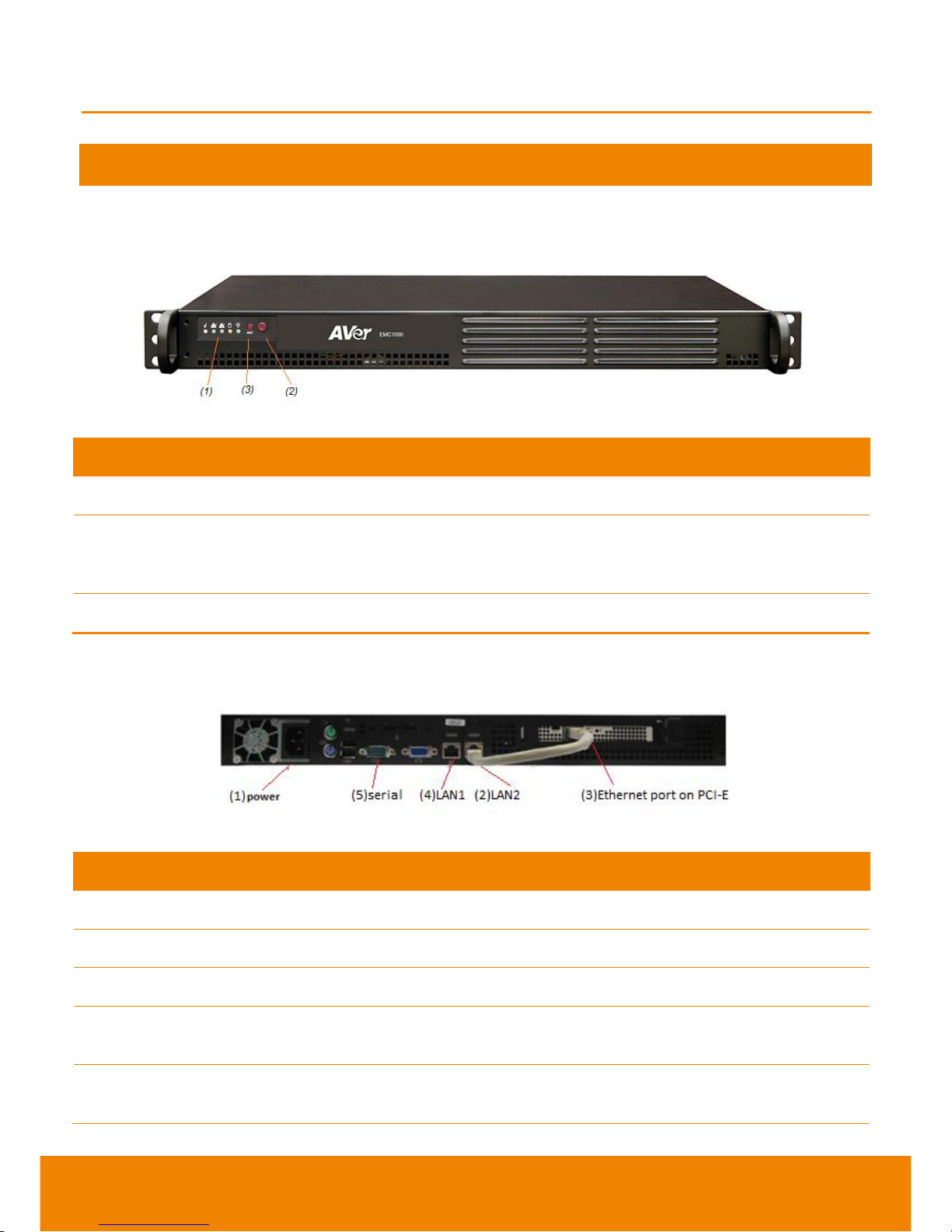
FRONT PANEL
Name
Function
(1) LED Indicator
Power, HD (harddisk), NIC1 (LAN1), NIC2 (LAN2) and overheat status
(2) POWER Button
Press this button to turn on/off the system. Power off shuts down the
main system power, keep standby power alive. Before service the
system, shutdown the system and pull the power plug off.
(3) RESET Button
Reboot the system.
BACK PANEL
Name
Function
(1) POWER Port
Connect the power supply cord to a suitable power outlet.
(2) LAN2 Port
(3) Ethernet Port PCI-E
Run the included gray CAT6 cable from (2) to (3).
(4) LAN1 port
Run the included orange cross cable to a PC to start your initial
configuration.
(5) serial port
In case orange cross cable not working properly, use serial port to
configure the system.
INSTALLATION
Page 7
5
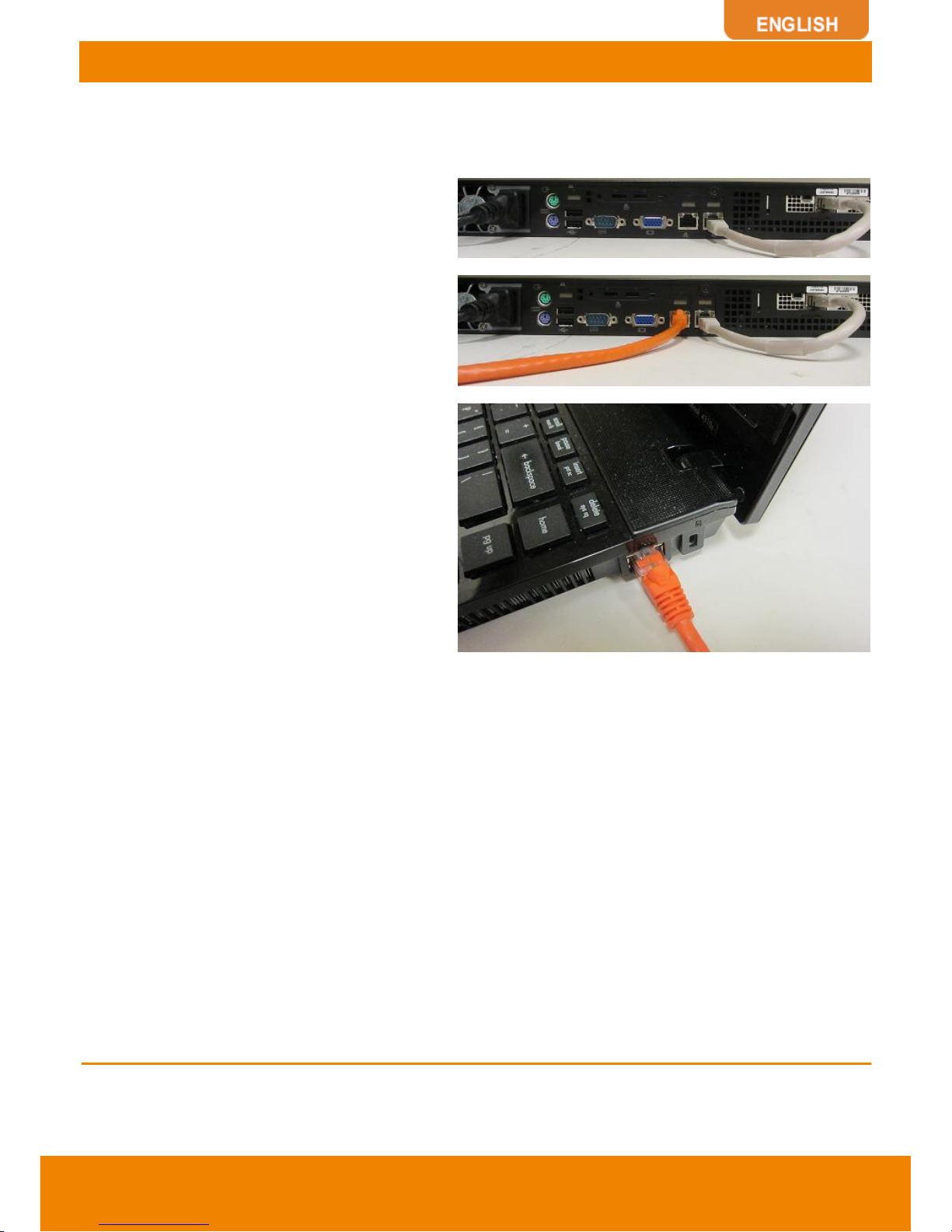
CONNECT THE EMC1000
Before making the connections, make sure all devices are powered off. EMC1000 factory IP address
is 192.168.0.1.
1. If you decide to put EMC1000 on the rack,
use the screws to secure it to rack.
2. Connect the power cable
3. Connect the beige/gray CAT6 cable
between LAN2 and PCI-E
4. Connect the orange cross cable between
LAN1 and PC
INITIAL SETUP
Page 8
6
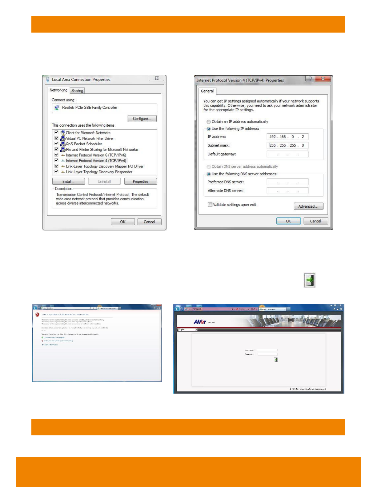
SET UP PC NETWORK
One the PC you use for EMC1000 initial setup, go to Control Panel, Network, Change Adapter Setting,
right mouse click Adapter Property. Only check “Internet Protocol Version 4 (TCP/IPv4)”, click on
“Properties”, change IP setting to “Use the following IP address”, enter the IP address and Subnet
mask indicating below.
Make sure the orange cross cable is connected properly from LAN1 on EMC1000 to the PC you just
did the network setting change. Open internet browser on that PC, type in 192.168.0.1 in URL, hit
enter. EMC1000 login screen appears in browser. CHANGE THE language via top left corner
language drop down list if needed.
EMC1000 default login is username admin and password admin. Enter both, click to enter
administration page.
NETWORK PLANNING
BANDWIDTH PLANNING
Page 9
7
As factory default, new conference is set at VGA quality low bandwidth. Each participant uses
512Kbps bandwidth. For a conference up to 10 VGA participants, it requires 512K x 10 = 5Mbps
bandwidth each way. If all 10 parties are coming from outside of company LAN, your internet needs
to reserve 5Mbps bandwidth during conference. If 5 out of 10 are inside LAN, 5 are outside, then you
need to reserve 2.5Mbps (512K x 5) bandwidth for EMC1000 during conference.
FIREWALL PLANNING
If you install EMC1000 inside company firewall and there are guest participants or remote employees
joining the conference. Likely you need to open the following ports on your firewall.
Port
Function
Type
5060, 5061, 5063
SIP
TCP and UDP
10000 to 11000
RTP media
TCP and UDP
80
HTTP Interface (WebTool)
TCP
NEAR-END NAT TRAVERSAL
In a deployment scenario where EMC1000 is located behind a firewall and is configured with private
IP address, the signaling sent from the EMC1000 messages will contain private IP addresses. Unless
the firewall provides VoIP NAT Traversal services, sessions will not connect, as the singling
messages will contain non-routable addresses. This issue is called Near-End NAT traversal, as the
problem to be solved is “near” – meaning the close firewall.
EMC1000 solves this problem by providing near-end NAT traversal as part of the EMC1000. The
private IP addresses within the SDP are replaced by the NAT’s public IP address and the clients
receive SIP messages which include SDP with accessible public IP addresses, providing session
completion.
1. Select System Settings, SIP Configuration
2. Click Edit
3. Check Enable Registrar / Proxy checkbox
4. Enter a value for Listening SIP Port
5. Check the MCU is behind NAT checkbox
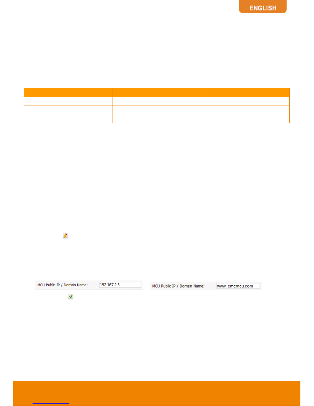
6. Enter a value for MCU Public IP / Domain Name:
or
7. Press Save to save the configuration
8. After the system restarts, Near-end NAT traversal is applied
Page 10

8
FAR-END NAT TRAVERSAL
When the SIP client is behind a firewall, EMC1000 may receive private IP addresses in the receive
SDP (for sending the session’s RTP packets). In this case, the packets cannot be sent before the
first packets are received from the cliebt. The system learns the actual public IP address of these
packets and sends the transmitted RTP packets to this address.
Far-end NAT traversal is applied automatically and no setting in needed in EMC1000.
In order for this topology to work, the SIP clients located behind the local firewall must support
Near-end NAT traversal.
Near-end NAT traversal for SIP clients requires the SIP clients sending their routable (in most cases
public) IP address in their contact information and r-port parameter.
Page 11

9
DECIDE EMC1000 NETWORK SETUP TOPOLOGY
Before you proceed further, let’s decide where you will put EMC1000.
If you don’t have EMC1000 compatible IP PBX or like to keep videoconferencing separate from VoIP,
you can have all HVC/EVC registers to EMC1000 built-in SIP registrar. To allow guests or remote
employees participate EMC1000 meeting directly, you will assign a public IP or public URL. Also,
you need to open firewall pinholes for EMC1000.
You can also put EMC1000 in DMZ (Demilitarized Zone of firewall) with LAN and public IP address.
If you have an EMC1000 compatible IP PBX and like to have EMC1000 and HVC/EVC register to PBX
as SIP clients. You may put EMC and HVC/EVC all inside LAN. To allow guests or remote
employees participate EMC1000 meeting directly, you will assign a public IP or public URL. Also,
you need to open firewall pinholes for EMC1000.
Page 12

10
CONFIGURE EMC1000 NETWORK
1. Go to system setting,
network setting, current
settings and status appear.
Click on to start setup.
2. After you finish the editting,
write down EMC1000 new
network settings, click
to apply the changes or
to discard the changes.
3. EMC1000 will reboot.
4. If you set the network to
DHCP, IP address may
change (usually not
recommended) and only
Hostname is editable.
Hostname and DNS are very
important for firmware
upgrade, SIP call with
domain name and
NAT/firewall traversal.
Make sure you remove the cross cable and connect EMC1000 to production network when EMC1000
reboots. Change your PC network setting back to the original setting (e.g. DHCP). Enter EMC1000
new IP address in internet browser URL. Log in using admin and admin.
Page 13

11
USER MANAGEMENT FOR WEB ACCESSING
.
Select User Management, you
can click on specific user
account to edit naming or
password. Or click on
to create
additional users. Admin role
has full access to all EMC1000
settings. User can only create,
view and control the
conference (meeting).
You can delete an existing
user by clicking .
Page 14

12
SIP CONFIGURATION
SIP parameters are in
SIP CONFIGURATION.
Click to start editing.
Page 15

13
SIP INTERFACE
Parameter
Vaules
Description
Listening SIP Port
Port
This parameter provides an additional SIP port for SIP interactions between
EMC1000 and external entities. The external entities can be SIP UAs like SIP
PBXs, or non-registered SIP clients.
SIP clients cannot register to EMC1000 through this port, to register with
EMC1000 the Listening SIP Port of the Built-in Registrar / Proxy should be used.
Block Direct Calls
Check-box
(Yes/No)
If this box is checked, direct incoming calls through “SIP Listening Port” (see
above), will be blocked.
BUILT-IN REGISTRAR / PROXY
Parameter
Vaules
Description
Enable Registrar / Proxy
Check-box (Yes/No)
If this box is checked then EMC1000 can be used as a registrar
for SIP clients.
Listening SIP Port
Port
This is EMC1000’s built-in listening SIP port, used for
registration of SIP clients and session establishments. It is
applicable only if “Enable Registrar / Proxy” (above) check-box
has been set.
REGISTER Authenticate
Required
Check-box (Yes/No)
“REGISTER Authenticate Required” is a check box that
determines the authentication of the managed users to
EMC1000. Managed users are users that are provisioned in
the system. If the box is checked, non-managed users are
not allowed to register with the system.
Authentication Realm
String
Authentication realm of EMC1000 built-in Registrar for
REGSITER digest challenge, any string can be used.
SIP Users
Add Users
Used to add new users to the system. This function is
applicable only when “Enable Registrar Proxy” and
“REGISTER Authenticate Required” check-boxes have been
checked. For more details, please refer to “Add Users”.
Show Users
Used to display the system’s users. This function is applicable
only when “Enable Registrar / Proxy” check-box has been set.
For more details, please refer to “Show Users”.
NAT Traversal
MCU is behind NAT
Check-box (Yes/No)
States whether the MCU is behind a NAT.
MCU Public IP / Domain
Name
IP address
SIP public IP address or domain name, used for near-end NAT
traversal. NAT Traversal is not applicable for sessions which
use SIP Interface: SIP Listening Port.
EXTERNAL REGISTRAR
Parameter
Vaules
Description
Use External
Registrar
Check-box
(Yes/No)
If an external registrar is configured, EMC1000 registers access numbers and
conference rooms to the external registrar.
Registrar IP/
Domain Name
IP address
The external registrar IP address or domain name
Registrar Port
Port
The external registrar SIP port
Use REGISTER
Check-box
Indicates whether the registration requires authentication.
Page 16

14
Authentication
(Yes/No)
Authentication
Realm
String
The Authentication realm of the External Registrar Must be the value sent in 401
response to REGISTER messages (Authentication is supported for REGISTER
only).
OUTBOUND PROXY
Parameter
Vaules
Description
Use Outbound
Proxy Server
Check-box
(Yes/No)
States whether an outbound proxy server is used.
In case that the EMC1000 is behind NAT or configured with public IP, and NAT
traversal (Near or Far end) is provided by EMC1000, the Outbound proxy server
should not be configured.
Outbound Proxy
Server IP
IP address
The Outbound proxy server IP address.
Outbound Proxy
Server Port
Port
The Outbound proxy server port
1. Click to discard the changes
and revert to previous settings.
Click to save the changes.
2. If any SIP parameter has been
modified, then all the active calls
will be dropped and the application
will restart. In this case the user’s
confirmation is required:
3. Click OK, the application restarts,
and the new configuration is
applied.
USE BUILT-IN SIP REGISTRAR
If you are setting up EMC1000 in an
environment without IP PBX or you plan to
use EMC1000 built-in SIP registrar, you will
check “Enable Registrar”. If you like to
enforce authentication for each SIP user,
check “REGISTER Authentication
Required” as well. If EMC1000 is installed
in NAT environment and you like to map it
to public IP for remote employees or guests
to join the call, check “MCU is behind NAT”
and enter public IP in “MCU Public IP /
Domain Name”.
Page 17

15
ADD SIP USERS
If you enable Built-in Registrar, you can add
SIP users by clicking . Click to
confirm the action.
SHOW AND EDIT SIP USERS
1. Click on to see all SIP users. You can edit each of them as well.
2. The columns on this screen can be sorted in ascending or descending order by clicking on any of
the column headers.
Filtering the Displayed List
3. The user is enabled to filter the displayed list, using the toolbar at the top of the table:
4. Filtering criteria are as follows:
Username. Type a full Username or a partial string from it.
SIP URI. Type a full SIP URI or a partial string of it.
Status. Choose Any, Registered and NON-Registered options, to see all the users, registered
or non-registered users accordingly, using the drop-down menu.
5. Pressing on Refresh resets the filter and the original list re-appears on the screen.
Managed Users
6. Managed Users are users that are provisioned in the system. Non-Managed Users are users
which are not provisioned in the system. Non-Managed users are allowed to register to use the
system only if the REGISTER Authentication Required parameter is not set.
Operation
7. To delete a user click on . A dialog-box
pop-up for user’s confirmation.
8. Modify Password:
Click on the following window opens, enter
the password.
Page 18

16
ACCESS NUMBERS
An access number is a number which a participant dials to connect to EMC1000. An interactive voice
response system directs the user to enter the conference number and the PIN code. However, access
numbers are not mandatory, since a participant can also join a conference by dialing directly the
conference number.
EMC1000 supports multiple access numbers. If the number dialed by a participant does not match any
of the provisioned access numbers (or conference numbers), the call is declined.
CONFIGURE ACCESS NUMBERS
Select System Settings,
Access Numbers.
Click “Create a new
number” . Enter the access
number participant needs to
dial and video quality from
Voice Only
Video Chat: CIF
(352x288)
VGA: 640x480
You can save it without further steps by clicking . If you like to register the access number to the
registrar, select Register. If you like to authenticate it, check Authenticate, it will ask you username
and password.
You can edit or delete existing access numbers by clicking or
.
Page 19

17
DATE AND TIME
1. You can set date, time, and
time zone manually or use
NTP server to auto set it.
2. To set date and time. System
Settings, Date & Time
3. After you finish, click to
save the changes.
Page 20

18
MAINTENANCE
Common maintenance tasks can be performed, including
View System Status – status of system components, general system information including CPU
usage, free and total memory.
Restart the Application – All ongoing conference (meeting) sessions drop, application restarts.
Hardware Reset - Reboot hardware. It takes about 3 minutes. It is recommended to log out and
re-login the system after Hardware Reset.
Shutdown – Enable graceful system shut-down. When shut-down, the server will completely power
off.
Start Diagnostic Trace – System events are collected during a specified interval, a trace file for
advanced diagnostic is created.
Enter the intervals for information collection between 0 to 300 seconds. Any number other than 0 will
create a detailed log. If 0 is entered, the system will create a system configuration and minimum log
information.
A diagnostic file (zip file) is created.
Click Save Diagnostic Trace to save the
file.
After saving the file, Delete Diagnostoc
Trace appears on the main Maintenance
screen. Only 1 diagnostic trace is
allowed to conserve disk space. After
you fetch the diagnostic trace, go ahead
delete it.
Page 21

19
UPGRADE
To upgrade the system software,
enter System Settings, Upgrade.
Enter “ezmeetup.averusa.com” in
the URL as the upgrade serve, the
latest firmware version will display if
DNS is setup properly. Check
Reboot and click Download when
you are ready. After download
completes, Start the upgrade button
appears.
Click it to start the upgrade, “The
system is upgrading. Please wait…”
appears followed by a Reboot
confirmation button. If you have
problem, please contact our
technical support.
CONFERENCE (MEETING) SUMMARY
You can select the “CONFERENCES”
from top center menu, it brings up a
summary of active conferences
(meetings). For example, meeting room
400 is active (busy), this video
(multimedia) call starts at 11:50a 8/8/2012
with 3 participants.
You can click to view more detailed
information regarding this meeting.
If you like to manage or make changes to this ongoing meeting, click Leader Dashboard. More
details will be covered later.
Page 22

20
CONFERENCE (MEETING) SETTINGS
You can select “CONFERENCE
SETTINGS” on the left, it brings up a list
of conferences (meeting rooms) have
been setup. You can delete any single
one by clicking .
If you like to create a new conference,
click on . You can give a name to
the conference, choose Multimedia
(video call) or Voice only, video quality
can be VGA or Video Chat, Bandwidth
default to low (you can change it to
medium or high if your facility bandwidth
allows), layout is default to dominant
(you can change it to equal), max shown
participants can be changed as well.
To manage a conference, click to
bring up Leader Dashboard.
Parameter
Vaules
Description
Conference Name
String
The nickname of the conference
Media Type
Multimedia
Voice Only
The type of conference to be defined, Multimedia for Video conference or Voice only
for Voice conference.
Video Quality
Video Chat
VGA
Voice Only
The video quality of the conference
Video Chat: CIF (352X288), High: VGA (640x480), and Voice Only
Bandwidth
Allocation
Low
Medium
High
EMC1000 uses “Low” as a default value for every new conference room’s
“Bandwidth Allocation” parameter.
If there are no bandwidth restrictions in your environment, you may use “Medium” or
“High” for enhanced video quality.
Video Layout Type
Equal Layout
Dominant
Based
The type of the video conference layout. EMC1000 uses “Dominant based” as the
default value for every new conference room.
Max Shown
Participants
Number
Up to 16 shown participants for equal based layout or up to 8 shown participants for
dominant based layout.
Meeting Room
Number
Number
The meeting room (conference) can be accessed by direct dialing, if it is registered.
Also used as username for the leader dashboard login.
PIN Required?
Yes/No
If positive, the participant is required to enter PIN number to log into the conference.
Register?
Yes/No
If positive then the conference is registered to the external registrar.
Authenticate?
Yes/No
If positive then the conference is registered with authentication.
Username
String
If authentication chosen, a username needs to be entered.
Password
String
If authentication chosen, password needs to be entered.
Page 23

21
Participant PIN
Number
The participant PIN for logging into the conference
Leader PIN
Number
The conference leader PIN (should be different from the participant PIN). Also used
as password for the leader dashboard login.
Leader Required
Yes/No
Defines if the conference can start before the leader joins the conference or not, if
configured yes all regular participant will be placed on hold until the leader joins to the
conference.
VIP Participants
List of
numbers
Participants’ phone numbers or SIP URIs who can join the conference without
entering a participant PIN codes.
CONTENT SHARING
From AVer HVC or EVC systems (with proper firmware) can send and receive content while attending
a conference (meeting) hosted by EMC1000. After you dial in to the conference room, have your
content ready from computer (through VGA in port or ScreenShare software), press present button on
HVC/EVC remote controller. All HVC or EVC systems and EZMeetup app will receive the content.
EZMeetup and other EMC1000 compatible terminals can receive content sending from HVC and EVC.
DIALING TO A CONFERENCE
If the user is on a HVC/EVC or EZMeetup registered to EMC1000, they can dial to the access number
or the conference number. The following example illustrates various dialing options, assuming
Access number – 500
Conference number – 100
Participant PIN code – 1
EMC1000 domain – emc1000.com
EMC1000 public IP – 111.51.50.50
Participants is registered on PBX
Dialing
Option
PIN
Code
Operations and Prompts
Access
√
Dial 500 – Prompt: “Please enter your conference number followed by the # key”
USAGE OF EMC1000
Page 24

22
Number
Dial 100 – Prompt: “Please enter the conference PIN number followed by the # key”
Dial 1 – Connected to conference
Conference
Number
√
Dial 100 – Prompt “Please enter the conference PIN number
followed by the # key” Dial 1 – Connected to conference
Access
Number
Dial 500 – Prompt “Please enter your conference number
followed by the # key” Dial 100 – Connected to conference
Conference
Number
Dial 100 – Connected to conference
Participant is registered on EMC1000 built-in registrar
Dialing
Option
PIN
Code
Operations and Prompts
Access
Number
√
Dial 500 – Prompt “Please enter your conference number followed by the # key”
Dial 100 – Prompt “Please enter the conference PIN number followed by the # key”
Dial 1 – Connected to conference
Alternative option (Connecting without prompts):
Dial 500*100*1 – Connected to conference
Conference
Number
√
Dial 100 – Prompt “Please enter the conference PIN number followed by the # key”
Dial 1 – Connected to conference
Access
Number
Dial 500 – Prompt “Please enter your conference number followed by the # key”
Dial 100 – Connected to conference
Conference
Number
Dial 100 – Connected to conference
Participant is not registered
Dialing
Option
PIN
Code
Operations and Prompts
Access
Number
√
Dial 500 – Prompt “Please enter your conference number followed by the # key”
Dial 100 – Prompt “Please enter the conference PIN number followed by the # key”
Dial 1 – Connected to conference
Alternative option (Connecting without prompts):
Dial 500*100*1 – Connected to conference
Conference
Number
√
Dial 100 – Prompt “Please enter the conference PIN number followed by the # key”
Dial 1 – Connected to conference
Access
Number
Dial 500 – Prompt “Please enter your conference number followed by the # key”
Dial 100 – Connected to conference
Conference
Number
Dial 100 – Connected to conference
Page 25

23
LEADER DASHBOARD
The Leader Dashboard provides the following capabilities to the conference leader:
Invite participants to join the conference
Modify the status of the participant from dominant to non dominant and vice versa
Make a participant visible/invisible
Obtain call statistics
Mute/Unmute all participants
View detailed conference parameters
Remove participants from the conference
Modify the conference layout mode.
First, the leader logs in EMC1000 using his/her username and password.
On the main screen of leader dashboard, the following items are displayed.
Meeting Information – Meeting information includes conference and access numbers.
Total Bandwidth - Total bandwidth usage of incoming and outgoing sessions, updated every 5
seconds - displayed at the top of the toolbar.
Operational Buttons – The following operational buttons appear at the left side of the Leader
Dashboard window:
Invite Participants – Enables the leader to invite participants to join the conference.
Mute/Unmute All Participants
Show Statistics – Displays the conference’s detailed statistics information (section Error!
Reference source not found.).
Toolbar which includes Participants and Layout options (section Error! Reference source
not found.). Participants screen provides the default display of the main screen.
The list of the conference participants followed by icons - Each participant in the list is followed
by icons. Each icon represents an information about the participant’s state or /and enables the
user to toggle between the states, by clicking on it.
Page 26

24
Dominant participant
Participant (not Dominant)
Call statistics
Participant voice enabled
Video only conference
Participant voice muted
Visible, participant
Voice only participant
Participant video disabled
Remove participant
When you click on , more detailed information appear.
You can change the meeting layout in leader dashboard as well.
One of two layouts can be chosen:
Page 27

25
Dominant based: The dominant speaker’s image is larger than the other participants’ images
(The dominant speaker is automatically defined by energetic voice detection).
Equal Presence: All the images are displayed equally.
The red border shows the chosen layout. Click Apply Chosen Layout to Conference to select a
layout.
Statistic displays more detailed information about this current going meeting.
Use the horizontal scroll bar to view all the participan’s information.
Set the Auto Refresh check-box to update the displayed information automatically. The information is
updated every 5 seconds.
The rows in the statistics table above can be set or reset by clicking on the Rows Settings button.
To invite paticipants, click on that button.
Enter the name or number, of who you want to invite, appears in the registration to SIP registrar if
EMC1000 is registered too. Or you can invite non-registered participant by entering the full path
including the SIP server IP address: name/number@SIP server-IP-Address. Click to add more
and click “Invite”.
Page 28

26
Page 29

27
Hardware
Dimensions
17 x 10 x 1.4 in (432 x 254 x 36 mm)
Chassis
1U Rackmountable
Weight:
Gross Weight: 10 lbs. (4.5 kg.)
System Input Requirements
AC Input Voltage: 100-240 VAC (auto-range)
Rated Input Current: 3A max.
Rated Input Frequency: 50 to 60 Hz
Power Supply
Rated Output Power: 200W (Part# PWS-202-1H)
Rated Output Voltages: +3.3V (8A), +5V (8A), +12V (16A), -12V
(0.5A), +5Vsb (2A)
Operating Environment
Operating Temperature: 10º to 35º C (50º to 95º F)
Non-operating Temperature: -40º to 70º C (-40º to 158º F)
Operating Relative Humidity: 8% to 90% (non-condensing)
Non-operating Relative Humidity: 5 to 95% (non-condensing)
Control Information
Web-based GUI
EMC1000 web based GUI supports Internet Explorer 8 or newer,
Google Chrome 20 or newer, Mozilla Firefox 14 or newer and Safari 5
or newer.
SPECIFICATIONS
TROUBLESHOOTING
Page 30

28
For a period of time beginning on the date of purchase of the applicable product and extending as set
forth in the “Warranty Period of AVer Product Purchased” section of the warranty card, AVer
Information Inc. (“AVer”) warrants that the applicable product (“Product”) substantially conforms to
AVer’s documentation for the product and that its manufacture and components are free of defects in
material and workmanship under normal use. “You” as used in this agreement means you individually
or the business entity on whose behalf you use or install the product, as applicable. This limited
warranty extends only to you as the original purchaser. Except for the foregoing, the Product is
provided “AS IS.” In no event does AVer warrant that You will be able to operate the Product without
problems or interruptions, or that the Product is suitable you’re your purposes. Your exclusive remedy
and the entire liability of AVer under this paragraph shall be, at AVer’s option, the repair or
replacement of the Product with the same or a comparable product. This warranty does not apply to
(a) any Product on which the serial number has been defaced, modified, or removed, or (b) cartons,
cases, batteries, cabinets, tapes, or accessories used with this product. This warranty does not apply
to any Product that has suffered damage, deterioration or malfunction due to (a) accident, abuse,
misuse, neglect, fire, water, lightning, or other acts of nature, commercial or industrial use,
unauthorized product modification or failure to follow instructions included with the Product, (b)
misapplication of service by someone other than the manufacturer’s representative, (c) any shipment
damages (such claims must be made with the carrier), or (d) any other causes that do not relate to a
Product defect. The Warranty Period of any repaired or replaced Product shall be the longer of (a) the
original Warranty Period or (b) thirty (30) days from the date of delivery of the repaired or replaced
product.
LIMITATIONS OF WARRANTY
AVer makes no warranties to any third party. You are responsible for all claims, damages,
settlements, expenses, and attorneys’ fees with respect to claims made against you as a result of your
use or misuse of the Product. This warranty applies only if the Product is installed, operated,
maintained, and used in accordance with AVer specifications. Specifically, the warranties do not
extend to any failure caused by (i) accident, unusual physical, electrical, or electromagnetic stress,
neglect or misuse, (ii) fluctuations in electrical power beyond Aver specifications, (iii) use of the
Product with any accessories or options not furnished by AVer or its authorized agents, or (iv)
installation, alteration, or repair of the Product by anyone other than AVer or its authorized agents.
DISCLAIMER OF WARRANTY
EXCEPT AS EXPRESSLY PROVIDED OTHERWISE HEREIN AND TO THE MAXIMUM EXTENT
PERMITTED BY APPLICABLE LAW, AVER DISCLAIMS ALL OTHER WARRANTIES WITH
RESPECT TO THE PRODUCT, WHETHER EXPRESS, IMPLIED, STATUTORY OR OTHERWISE,
INCLUDING WITHOUT LIMITATION, SATISFACTORY QUALITY, COURSE OF DEALING, TRADE
USAGE OR PRACTICE OR THE IMPLIED WARRANTIES OF MERCHANTABILITY, FITNESS FOR
A PARTICULAR PURPOSE OR NONINFRINGEMENT OF THIRD PARTY RIGHTS.
LIMITED WARRANTY
Page 31

29
LIMITATION OF LIABILITY
IN NO EVENT SHALL AVER BE LIABLE FOR INDIRECT, INCIDENTAL, SPECIAL, EXEMPLARY,
PUNITIVE, OR CONSEQUENTIAL DAMAGES OF ANY NATURE INCLUDING, BUT NOT LIMITED
TO, LOSS OF PROFITS, DATA, REVENUE, PRODUCTION, OR USE, BUSINESS INTERRUPTION,
OR PROCUREMENT OF SUBSTITUTE GOODS OR SERVICES ARISING OUT OF OR IN
CONNECTION WITH THIS LIMITED WARRANTY, OR THE USE OR PERFORMANCE OF ANY
PRODUCT, WHETHER BASED ON CONTRACT OR TORT, INCLUDING NEGLIGENCE, OR ANY
OTHER LEGAL THEORY, EVEN IF AVER HAS ADVISED OF THE POSSIBILITY OF SUCH
DAMAGES. AVER’S TOTAL, AGGREGATE LIABILITY FOR DAMAGES OF ANY NATURE,
REGARDLESS OF FORM OF ACTION, SHALL IN NO EVENT EXCEED THE AMOUNT PAID BY
YOU TO AVER FOR THE SPECIFIC PRODUCT UPON WHICH LIABILITY IS BASED.
GOVERNING LAW AND YOUR RIGHTS
This warranty gives you specific legal rights; you may also have other rights granted under state law.
These rights vary from state to state.
Page 32

30
NOTE- This equipment has been tested and found to comply with the limits for a Class A digital
device, pursuant to Part 15 of the FCC Rules. These limits are designed to provide reasonable
protection against harmful interference in a residential installation. This equipment generates uses
and can radiate radio frequency energy and, if not installed and used in accordance with the
instructions, may cause harmful interference to radio communications. However, there is no
guarantee that interference will not occur in a particular installation. If this equipment does cause
harmful interference to radio or television reception, which can be determined by tuning the equipment
off and on, the user is encouraged to try to correct the interference by one or more of the following
measures:
1. Reorient or relocate the receiving antenna.
2. Increase the separation between the equipment and receiver.
3. Connect the equipment into an outlet on a circuit different from that to which the receiver is
connected.
4. Consult the dealer or an experienced radio/television technician for help.
For warranty period, please refer to the warranty card.
FEDERAL COMMUNICATIONS COMMISSION
STATEMENT (CLASS A)
Page 33

31
© 2013 by AVer Information Inc. All rights reserved. No part of this publication may be reproduced,
transmitted, transcribed, stored in a retrieval system, or translated into any language in any form by
any means without the written permission of AVer Information Inc.
TRADEMARKS
AVer is registered trademarks of AVer Information Inc. Other trademarks used herein for description
purpose only belong to each of their companies.
DISCLAIMER
No warranty or representation, either expressed or implied, is made with respect to the contents of this
documentation, its quality, performance, merchantability, or fitness for a particular purpose.
Information presented in this documentation has been carefully checked for reliability; however, no
responsibility is assumed for inaccuracies. The information contained in this documentation is subject
to change without notice. In no event will AVer be liable for direct, indirect, special, incidental, or
consequential damages arising out of the use or inability to use this product or documentation, even if
advised of the possibility of such damages.
AVer Information Inc.
Website: http://www.aver.com
COPYRIGHT
 Loading...