

Avdel Avbolt 07220, Avbolt T10, Avbolt T30 Assembly Instructions Manual
5
Intent of Use
Tool Specification
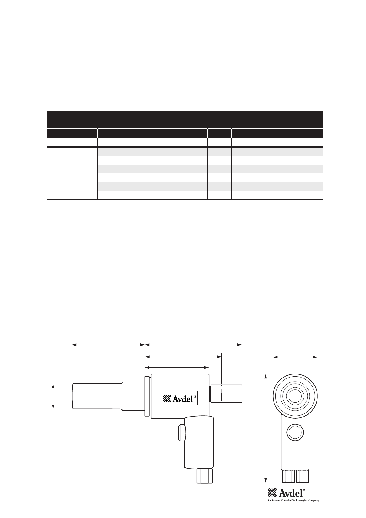
Tool Dimensions
Specifications
The T10 Installation Tool is basically a Piston and Cylinder Assembly. When coupled Hydraulically and Electrically to a compatible
Hydraulic Power Source and the relevant Nose Assembly is attached, it is then used to install
3
/8” Avdelok®, 5/16” to 3/8” Avbolt®and
16mm to 20mm Avseal
®
in Industrial Environments.
Refer to the table below for the list of applicable fasteners and associated nose equipment.
Refer to the datasheets listed in the table for the relevant nose assembly insructions.
Length 158 mm 6.25 in
Body Diameter 60 mm 2.36 in
Height 176 mm 6.93 in
Weight 3.5 kg 7.7 lbs
Stroke 25 mm 1 in
Pull-Force 58kN 13040 lbf
Pull pressure 55.2 mPa 8000 PSI
Return Pressure 20.7 mPa 3000 PSI
Hydraulic Oil ISO VG 46 OR EQUIVALENT
Fastener Range 5 to 10 mm incl. M.G. & Blind Fasteners
Noise Level Below reportable levels
Sound Power Below reportable levels
Vibration Below reportable levels
TYPE SIZE
Avdelok
Avbolt
Avseal
FASTENER
®
®
®
3
/
î (10mm)
8
5
/
3
/
16mm
16mm flanged
18mm
20mm
NOSE ASSEMBLY
PART Nº HAT REF. DIM. ‘A’
73411-03100
”
16
”
8
73411-03300
73411-03200
73411-05000
73411-05000
73411-05200
73411-05400
N10
-
N11
-
-
-
-
NOSE ASSEMBLY
DIM. ‘B’ PART Nº
28mm89mm
27mm86mm
29mm86mm
27mm89mm
27mm89mm
27mm89mm
27mm89mm
DATASHEET
07900-00919
07900-00905
07900-00905
07900-00840
07900-00840
07900-00840
07900-00840
158 mmA
118 mm
60 mm
98 mm
B
176 mm
This technical datasheet must be read with particular attention to the safety rules and operating instructions
listed in the 07220 (07900-00648), T10 (07900-00820) and T30 (07900-00821) Instruction Manuals, by any
person fitting or operating the Avbolt
®
nose assemblies and hand tools.
The Avbolt
®
nose assemblies in combination with the 07220, T10 and T30 tools are designed for placing Avdel®Avbolt
®
structural fasteners only. The correct placing tool and nose assembly must be selected for each fastener size as shown in
Table 1 below.
I M P O R T A N T
The tools and nose assemblies must be used in accordance with the safety rules and fitting instructions
contained within this datasheet and the tool instruction manual. The placing of fasteners not included in this
datasheet could have a detrimental impact on the working life of the tool and nose assemblies and could
invalidate the warranty.
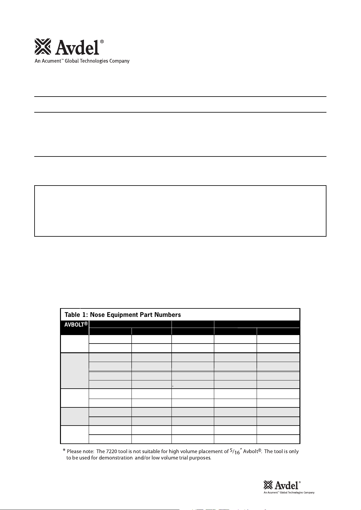
The Table 1 below provides a full list of part numbers, nose assemblies and base tools required to place each Avbolt®size.
This table should be used to select and order the correct placing equipment.
Please note that there are two variants of nose equipment available to fit either Avdel
®
or Huck®hand tools.
For the fitting and servicing instructions for each nose assembly refer to the page number provided in Table 1.
1
Avbolt®Nose Assembly Instructions
07220, T10 and T30 Tools
Safety Rules
Intent of Use
Table 1: Nose Equipment Part Numbers
AVBOLT
SIZE
”
1
/
4
”
5
/
16
”
3
/
8
”
1
/
2
”
5
/
8
®
NOSE ASSEMBLY
PART No REF. PAGE
07220-07500
07220-07600
07220-07700
07220-07800 73411-033034
73411-03300 73411-033036
73411-03400 73411-033036
73411-03200
73411-03500
73412-03400
73412-03500
*
-
-
2
2
4
8
8
10
10
JAWS
PART No
07220-07502
07220-07502
73411-03303
73411-03203
73411-03203
73412-03403
73412-03403
BASE TOOL
MODEL PART No
7220
®
HUCK
256
7220
*
®
HUCK
256
T10
®
2600
HUCK
T10
®
HUCK
2600
--
--
T30
HUCK
-
-
®
585
07220-00200
-
07220-00200
-
73411-02000
-
73411-02000
-
-
-
73412-02000
-
*
* Please note: The 7220 tool is not suitable for high volume placement of
to be used for demonstration and/or low volume trial purposes.
5
”
/
Avbolt®. The tool is only
16
2
1
/
4
” Avbolt®Nose Assemblies - 07220-07500 and 07220-07600
I M P O R T A N T
The air supply must be disconnected when fitting or removing nose assemblies.
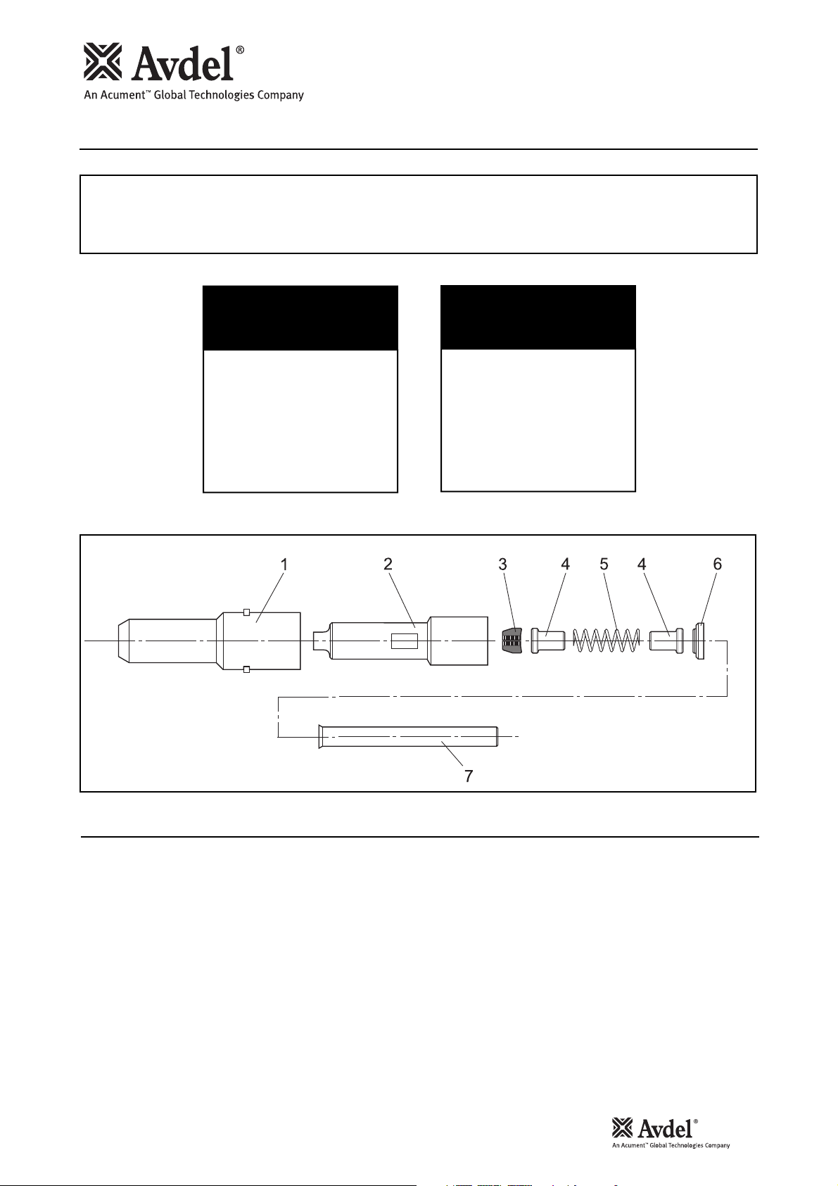
Item numbers in bold refer to nose assembly components in the tables and illustration above.
• Lightly coat Jaws 3 with Moly Lithium grease.
• Assemble Spring Guide 4 and Spring 5 and stand on end on a flat even surface.
• Balance the three Jaws 3 on the upper Spring Guide 4.
• Carefully lower Collet 2 over the assembled components.
• Holding the assembled collet pointing downwards insert Spacer 6 behind the rear Spring Guide 4.
• Insert Pintail Tube 7 into the tool head piston bore.
• Holding the tool pointing down, screw the assembled collet fully onto the tool head piston and tighten with a suitable
spanner.
Fitting Instructions
NOSE ASSEMBLY
for Avdel® 07220 tool
part nº 07220-07500
ITEM DESCRIPTION
1 ANVIL 07220-07501
2 COLLET 07220-07503
3 JAWS 07220-07502
4 SPRING GUIDE 07220-02104
5 SPRING 07220-02103
6 SPACER 07220-07504
7 PINTAIL TUBE 07220-07505
P
ART Nº
NOSE ASSEMBLY
for Huck® 256 tool
part nº 07220-07600
ITEM DESCRIPTION
1 ANVIL 07220-07501
2 COLLET 07220-07503
3 JAWS 07220-07502
4 SPRING GUIDE 07220-02104
5 SPRING 07220-02103
6 SPACER - HUCK
7 PINTAIL TUBE 07220-07505
P
ART Nº
®
07220-07601

3
1
/
4
” Avbolt®Nose Assemblies - 07220-07500 and 07220-07600
07220 Tool:
• Place Anvil 1 over Collet 2 and onto the tool, ensuring that the lugs on the body enter the slots in the
head extension of the tool.
• Turn the reducing adaptor body through 90° then turn the head extension ring until it springs into its position
in the slots of the head extension.
Huck
®
256 Tool:
• Place Anvil 1 over Collet 2 and into the tool. Slide the retainer nut over Anvil 1, screw fully onto the
tool and tighten by hand.
Servicing Instructions
Nose assemblies should be serviced at weekly intervals. You should hold some stock of all internal components
of the nose assembly as they will need regular replacement.
• Remove the nose assembly using the reverse procedure to the ‘Fitting Instructions’.
• Any worn or damaged part should be replaced.
• Clean and check wear on Jaws 3.
• Check that Spring 5 and Spring Guides 4 are not distorted.
• Clean and inspect components, renewing worn or damaged items.
• Assemble according to the ‘Fitting Instructions’.
Fitting Instructions
4
5
/
16
”
Avbolt
®
Nose Assemblies - 07220-07700 and 07220-07800
I M P O R T A N T
The air supply must be disconnected when fitting or removing nose assemblies.
Please note: The 7220 tool is not suitable for high volume placement of
5
/
16
”
Avbolt®. The tool is only to be used
for the demonstration and/or low volume trial purposes.
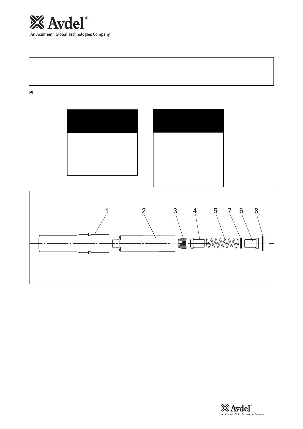
Item numbers in bold refer to nose assembly components in the tables and illustration above.
07220 Tool:
• Lightly coat Jaws 3 with Moly Lithium grease.
• Assemble Spring Guide 6, Spring 5 and Follower 4 and stand on end on a flat even surface.
• Balance the three Jaws 3 on Follower 4.
• Carefully lower Collet 2 over the assembled components.
• Holding the tool pointing down, screw the assembled collet fully onto the tool head piston and tighten with a suitable
spanner.
• Place Anvil 1 over Collet 2 and onto the tool, ensuring that the lugs on the body enter the slots in the head extension of
the tool.
• Turn the reducing adaptor body through 90° then turn the head extension ring until it springs into its position
in the slots of the head extension.
Fitting Instructions
NOSE ASSEMBLY
for Avdel® 07220 tool
part nº 07220-07700
ITEM DESCRIPTION
1 ANVIL 07220-07701
2 COLLET 07220-07702
3 JAWS 73411-03303
4 FOLLOWER 07220-07703
5 SPRING 07220-06305
6 SPRING GUIDE 07220-07704 SPRING GUIDE 07220-07704
P
ART Nº
NOSE ASSEMBLY
for Huck® 256 tool
part nº 07220-07800
ITEM DESCRIPTION
1 ANVIL 07220-07701
2 COLLET 07220-07702
3 JAWS 73411-03303
4 FOLLOWER 07220-07703
5 SPRING 07220-06305
6
8
SHIM 07220-078017
SHIM 07220-07802
P
ART Nº
78

5
5
/
16
”
Avbolt®Nose Assemblies - 07220-07700 and 07220-07800
Huck®256 Tool:
• Lightly coat Jaws 3 with Moly Lithium grease.
• Assemble Spring Guide 6, Shim 7, Sping 5 and Follower 4 and stand on end on a flat even surface.
• Balance the three Jaws 3 on Follower 4.
• Carefully lower Collet 2 over the assembled components.
• Holding the assembled collet pointing downwards, insert the Shim 8 behind the Spring Guide 6.
• Holding the tool pointing down, screw the assembled collet fully onto the tool head piston and tighten with a suitable
spanner.
• Place Anvil 1 over Collet 2 and into the tool. Slide the retainer nut over Anvil 1, screw fully onto the
tool and tighten by hand.
Servicing Instructions
Nose assemblies should be serviced at weekly intervals. You should hold some stock of all internal components
of the nose assembly as they will need regular replacement.
• Remove the nose assembly using the reverse procedure to the ‘Fitting Instructions’.
• Any worn or damaged part should be replaced.
• Clean and check wear on Jaws 3.
• Check that Spring 5, Follower 4 and Spring Guide 6 are not distorted.
• Clean and inspect components, renewing worn or damaged items.
• Assemble according to the ‘Fitting Instructions’.
Fitting Instructions

6
5
/
16
”
Avbolt
®
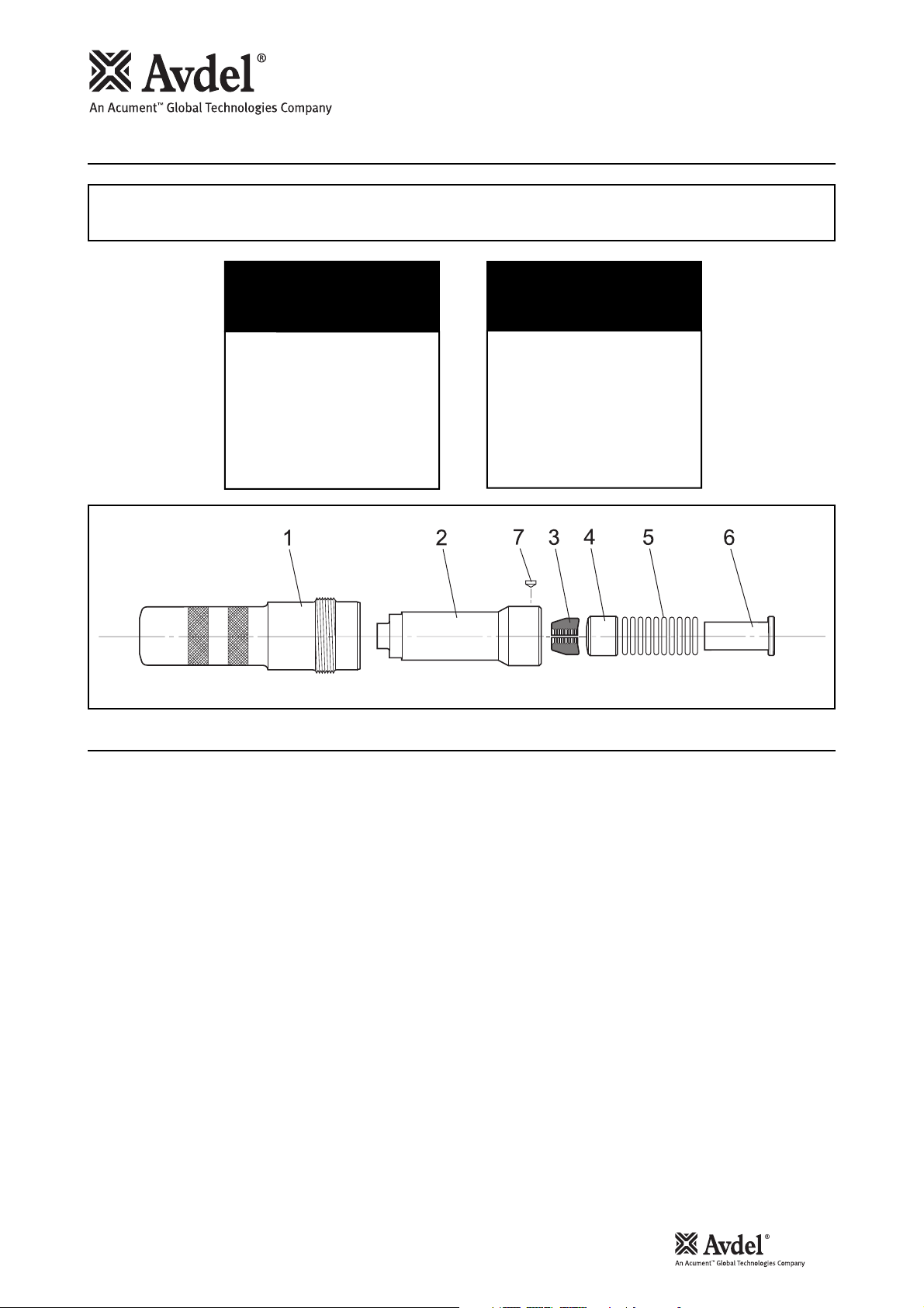
Nose Assemblies - 73411-03300 and 73411-03400
I M P O R T A N T
Be sure the tool power supply is turned off before fitting or removing the nose assembly.
Item numbers in bold refer to nose assembly components in the tables and illustration above.
• Lightly coat Jaws 3 with Moly Lithium grease.
• On a flat work surface, assemble the Sleeve 6, ‘O’ Rings 5, Follower 4 and Jaws 3 by stacking vertically in that order.
• Place the Collet 2 over the assembled stack, slide to the end of the work surface and with a finger, push the stack fully
inside the Collet.
T10 Tool:
• Holding the tool pointing down, screw the assembled collet fully onto the piston rod until it is flush with the end of the
collet adaptor.
• Insert Collet Lock 7 into Collet 2. Rotate Collet 2 on the piston rod in either direction until Collet Lock 7 slots into the
nearest groove in the collet adaptor. The Collet Lock 7 should be flush with the exterior of Collet 2.
• Slide Anvil 1 over the collet and screw into the anvil adaptor until it is firm.
• There is a locking ‘O’ Ring which will create a resistance to the final few turns of the nose casing. It is imperative that the
nose casing be hand tightened up against the rear locking face.
Huck
®
2600 Tool:
• Holding the tool pointing downwards, screw the assembled collet onto the piston rod until it bottoms out.
• Insert Collet Lock 7 into Collet 2. Rotate Collet 2 on the piston rod in either direction until Collet Lock 7 slots into the
nearest groove on the piston rod. The Collet Lock 7 should be flush with the exterior of Collet 2.
• Place Anvil 1 over Collet 2 and into the tool. Slide the retainer nut over Anvil 1, screw fully onto the tool and tighten by
hand.
Fitting Instructions
NOSE ASSEMBLY
ITEM DESCRIPTION
1 ANVIL 73411-03301
2 COLLET 73411-03302
3 JAWS 73411-03303
4 FOLLOWER 73411-03304
56 ‘O’ RINGS 07003-00426
7 COLLET LOCK 73411-05004
for Avdel T10 tool
part nº 73411-03300
P
ART Nº
SLEEVE 73411-03305
NOSE ASSEMBLY
for Huck 2600 tool
part nº 773411-03400
ITEM DESCRIPTION
1 ANVIL-HUCK 73411-03401
2 COLLET-HUCK 73411-03402
3 JAWS 73411-03303
4 FOLLOWER 73411-03304
5 ‘O’ RINGS 07003-00426
6 SLEEVE 73411-03305
7 COLLET LOCK 73411-05004
P
ART Nº
10 off

7
5
/
16
”
Avbolt®Nose Assemblies - 73411-03300 and 73411-03400
Servicing Instructions
Nose assemblies should be serviced at weekly intervals. You should hold some stock of all internal components
of the nose assembly as they will need regular replacement.
• Remove the nose assembly using the reverse procedure to the ‘Fitting Instructions’.
• Any worn or damaged part should be replaced.
• Clean and check wear on Jaws 3.
• Check that Follower 4, Sleeve 6 and ‘O’ Rings 5 are not distorted.
• Assemble according to the ‘Fitting Instructions’.
8
3
/
8
”
Avbolt®Nose Assemblies - 73411-03200 and 73411-03500
IMPORTANT
Be sure the tool power supply is turned off before fitting or removing the nose assembly.
Fitting Instructions
Item numbers in bold refer to nose assembly components in the tables and illustration above.
• Lightly coat Jaws 3 with Moly Lithium grease.
• On a flat work surface, assemble Sleeve 6, ‘O’ Rings 5, Follower 4 and Jaws 3 by stacking vertically in that order.
• Place Collet 2 over the assembly stack, slide to the end of the work surface and with a finger, push the stack fully into
Collet 2.
T10 Tool:
• Holding the tool pointing down, screw the assembled collet onto the piston rod until it is flush with the end of the
collet adaptor.
• Insert Collet Lock 7 into Collet 2. Rotate Collet 2 on the piston rod in either direction until Collet Lock 7 slots into the
nearest groove on the collet adapter. The Collet Lock 7 should be flush with the exterior of Collet 2.
• Slide Anvil 1 over Collet 2 and screw into the anvil adaptor until it is firm.
• There is a locking 'O' ring which will create a resistance to the final few turns of the nose casing. It is imperative that the
nose casing be hand tightened up against the rear locking face.
Huck
®
2600 Tool:
• Holding the tool pointing down, screw the assembled collet onto the piston rod until it bottoms out.
• Insert Collet Lock 7 into Collet 2. Rotate Collet 2 on the piston rod in either direction until Collet Lock 7 slots into the
nearest groove on the piston rod. The Collet Lock 7 should be flush with the exterior of Collet 2.
• Place Anvil 1 over Collet 2 and into the tool. Slide the retainer nut over the Anvil 1, screw fully onto the tool and tighten by
hand.
NOSE ASSEMBLY
for Avdel® T10 tool
part nº 73411-03200
ITEM DESCRIPTION
1 ANVIL 73411-03201
2 COLLET 73411-03202
3 JAWS 73411-03203
4 FOLLOWER 73411-03204
56 ‘O’ RINGS 07003-00426
7 COLLET LOCK 73411-05004
SLEEVE 73411-03205
P
ART Nº
NOSE ASSEMBLY
for Huck® 2600 tool
part nº 73411-03500
ITEM DESCRIPTION
1 ANVIL-HUCK
2 COLLET-HUCK® 73411-03502
3 JAWS 73411-03203
4 FOLLOWER 73411-03204
5 ‘O’ RINGS 07003-00426
6 SLEEVE 73411-03205
7 COLLET LOCK 73411-05004
P
ART Nº
®
73411-03501
10 off

9
3
/
8
”
Avbolt®Nose Assemblies - 73411-03200 and 73411-03500
Nose assemblies should be serviced at weekly intervals. You should hold some stock of all internal components of the nose
assembly as they will need regular replacement.
• Remove the nose assembly using the reverse procedure to the ‘Fitting Instructions’.
• Any worn or damaged part should be replaced.
• Clean and check wear on Jaws 3.
• Check that Follower 4, Sleeve 6 and ‘O’ Rings 5 are not distorted.
• Assemble according to the ‘Fitting Instructions’.
Servicing Instructions
10
5
/
8
”
Avbolt
®
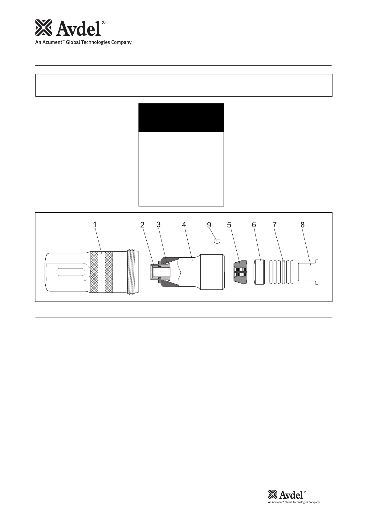
Nose Assembly - 73412-03400 for Avdel®T30
IMPORTANT
Be sure the tool power supply is turned off before fitting or removing the nose assembly.
Fitting Instructions
Item numbers in bold refer to nose assembly components in the table and illustration above.
• Lightly coat Jaws 5 with Moly Lithium grease.
• On a flat work surface, assemble Sleeve 8, ‘O’ Rings 7, Follower 6 and Jaws 5 by stacking vertically in that order.
• The Collet 4 will be supplied pre-assembled with Collar Ejector 2 and Jaw Release 3 as shown.
• Place Collet 4 over the assembled stack, slide to the end of the work surface and with a finger, push the stack fully
inside Collet 4.
• Holding the tool pointing down, screw the assembled collet onto the piston rod until it is flush with the end of the collet
adaptor.
• Insert Collet Lock 9 into Collet 4. Rotate Collet 4 on the piston rod in either direction until Collet Lock 9 slots into the
nearest groove on the collet adapter. The Collet Lock 9 should be flush with the exterior of Collet 4.
• Slide Anvil 1 over Collet 4 and screw into the anvil adaptor until it is firm.
• There is a locking 'O' ring which will create a resistance to the final few turns of the nose casing. It is imperative that the
nose casing be hand tightened up against the rear locking face.
• Correct installation of the nose assembly can be gauged by the free movement of the correct size pintail through the
assembled jaws in the nose.
NOSE ASSEMBLY
for Avdel® T30 tool
part nº 73412-03400
ITEM DESCRIPTION
1 ANVIL 73412-03401
2 COLLAR EJECTOR 73412-03408
3 JAW RELEASE 73412-03406
4 COLLET 73412-03402
5 JAWS 73412-03403
6 FOLLOWER 73412-03404
7
‘O’ RINGS 07003-00427
8 SLEEVE 73412-03405
9 COLLET LOCK 73412-03407
P
ART Nº
6 off

11
5
/
8
”
Avbolt®Nose Assembly - 73412-03400 for Avdel®T30
Nose assemblies should be serviced at weekly intervals. You should hold some stock of all internal components
of the nose assembly as they will need regular replacement.
• Remove the nose assembly using the reverse procedure to the ‘Fitting Instructions’.
• Any worn or damaged part should be replaced.
• Clean and check wear on Jaws 5.
• Check that Collar Ejector 2, Follower 6, Sleeve and ‘O’ Rings 7 are not distorted.
• To remove a damaged or worn Collar Ejector 2 cut at a point between the flange of the ejector and the end of Collet 4.
The Collar Ejector 2 and Jaw Release 3 can then be separated and removed from Collet 4.
• When assembling a new Collar Ejector 2 and Jaw Release 3 in Collet 4, first ensure that the threads are clean, before
applying Loctite
®
243 and screwing the two parts together within Collet 4.
• Assemble according to the ‘Fitting Instructions’.
Servicing Instructions
 Loading...