

Avdel 7537 User Manual
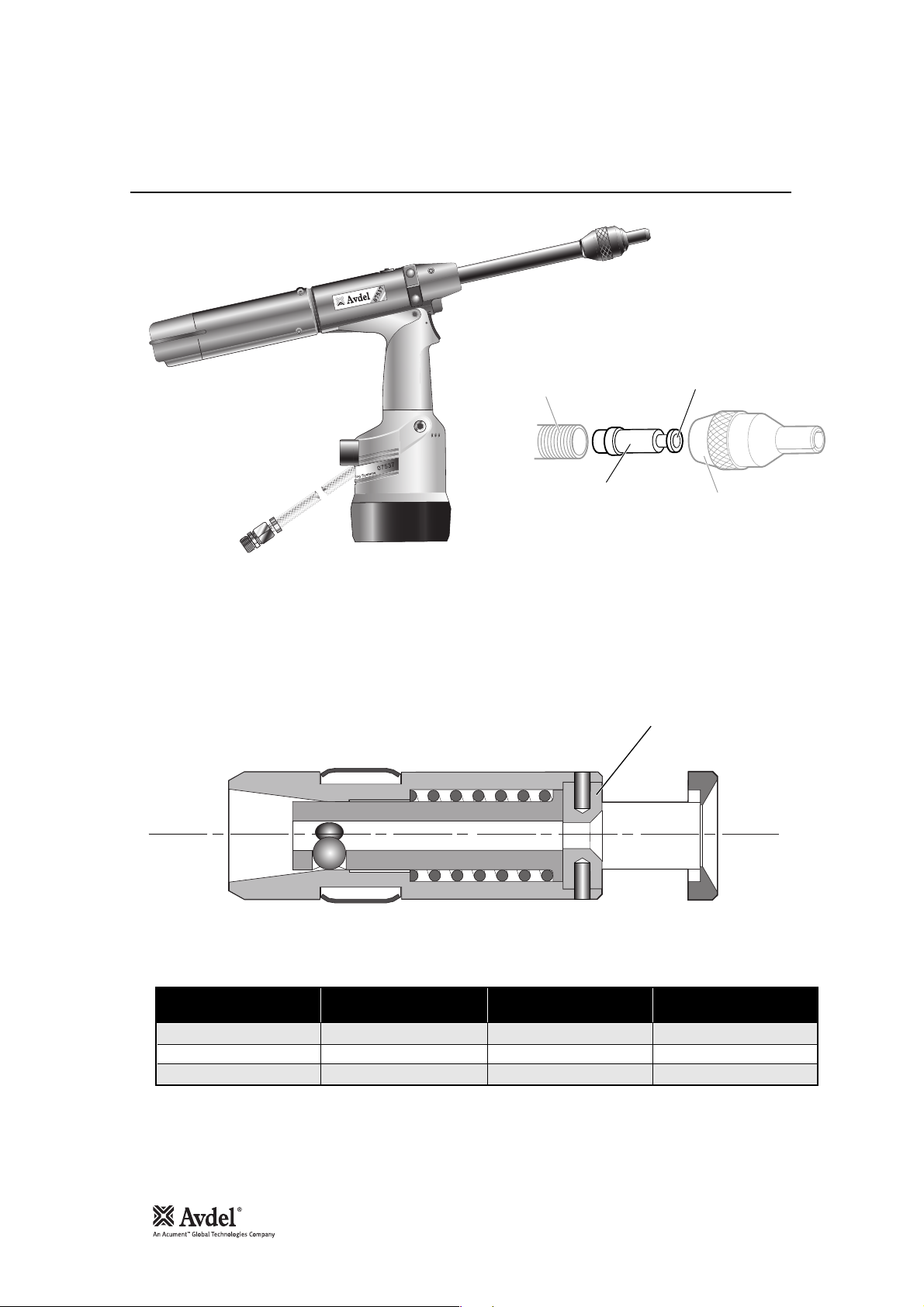
Genesis®7537
Hydro-Pneumatic Power Tool
Druckluftgerät
Outil oléo-pneumatique
Attrezzo oleopneumatico
Instruction Manual
Manuel d’instructions
Betriebsanleitung
Manuale d’istruzione
07537
07537


3
Contents
Safety Rules 4
Specifications
Specification for 7537 Tool 5
Tool Dimensions 5
Intent of Use 6
Putting into Service
Air Supply 7
Mechanical Cursors 8
Cursor 9
Loading and Reloading the Tool 10
Operating Procedure 10
Mandrel Follower Springs Identification 11
and Orientation
Nose Assemblies
Nose Jaws 12
Selecting a Nose Jaw 13
Nose Jaw Selection - Imperial 14
Nose Jaw Selection - Metric 15
Mandrels and Mandrel Follower Springs 16
Chobert®and Grovit®- Imperial 16
Chobert®and Grovit®- Metric 17
Briv®- Imperial 18
Mandrel Head Types and ‘P’ Length 19
Briv®- Metric 19
Avlug®, Avsert®, Avtronic®and Rivscrew
®
Imperial and Metric 20
Servicing the Tool
Daily 21
Weekly 21
MolyLithium Grease EP 3735 Safety Data 21
Molykote®55m Safety Data 22
Molykote®111 Safety Data
Service Kits 23
Maintenance
Dismantling 07537-00200 24-25
General Assembly and Parts List 07537-00200 26-27
Priming
Oil Details 28
Hyspin®VG 32 and AWS 32 Oil Safety Data 28
Priming Kit 28
Priming Procedure 29
Fault Diagnosis
Symptom, Possible Cause and Remedy 30
Français 33
Deutsch 63
Italiano 93
Avdel UK Limited policy is one of continuous product development and improvement and we reserve the right to change the specification of any product without prior notice.
English
LIMITED WARRANTY
Avdel makes the limited warranty that its products will be free of defects in workmanship and materials which
occur under normal operating conditions. This Limited Warranty is contingent upon: (1) the product being
installed, maintained and operated in accordance with product literature and instructions, and (2) confirmation
by Avdel of such defect, upon inspection and testing. Avdel makes the foregoing limited warranty for a period of
twelve (12) months following Avdel’s delivery of the product to the direct purchaser from Avdel. In the event of
any breach of the foregoing warranty, the sole remedy shall be to return the defective Goods for replacement or
refund for the purchase price at Avdel’s option. THE FOREGOING EXPRESS LIMITED WARRANTY AND REMEDY
ARE EXCLUSIVE AND ARE IN LIEU OF ALL OTHER WARRANTIES AND REMEDIES. ANY IMPLIED WARRANTY AS TO
QUALITY, FITNESS FOR PURPOSE, OR MERCHANTABILITY ARE HEREBY SPECIFICALLY DISCLAIMED AND
EXCLUDED BY AVDEL.

4
Safety Rules
This instruction manual must be read with particular attention to the following safety rules, by any person
installing, operating, or servicing this tool.
1 Do not use outside the design intent.
2 Do not use equipment with this tool/machine other than that recommended and supplied by Avdel UK Limited.
3 Any modification undertaken by the customer to the tool/machine, nose assemblies, accessories or any equipment supplied by
Avdel UK Limited or their representatives, shall be the customer’s entire responsibility. Avdel UK Limited will be
pleased to advise upon any proposed modification.
4 The tool/machine must be maintained in a safe working condition at all times and examined at regular intervals for damage and
function by trained competent personnel. Any dismantling procedure shall be undertaken only by personnel trained in Avdel UK
Limited procedures. Do not dismantle this tool/machine without prior reference to the maintenance instructions. Please contact
Avdel UK Limited with your training requirements.
5 The tool/machine shall at all times be operated in accordance with relevant Health and Safety legislation. In the U.K. the “Health and
Safety at Work etc. Act 1974” applies. Any question regarding the correct operation of the tool/machine and operator safety should
be directed to Avdel UK Limited.
6 The precautions to be observed when using this tool/machine must be explained by the customer to all operators.
7 Always disconnect the airline from the tool/machine inlet before attempting to adjust, fit or remove a nose assembly.
8 Do not operate a tool/machine that is directed towards any person(s) or the operator.
9 Always adopt a firm footing or a stable position before operating the tool/machine.
10 Ensure that vent holes do not become blocked or covered and that hoses are always in good condition.
11 The operating pressure shall not exceed 7 bar (100 lbf/in
2
).
12 The combination of fastener, mandrel, hole size and sheet thickness shall be in accordance with Avdel UK Limited Specifications.
13 Do not operate the tool if it is not fitted with a complete nose assembly unless specifically instructed otherwise.
14 When using the tool, the wearing of safety glasses is required both by the operator and others in the vicinity to protect against
fastener ejection, should a fastener be placed ‘in air’. We recommend wearing gloves if there are sharp edges or corners on the
application.
15 Take care to avoid entanglement of loose clothes, ties, long hair, cleaning rags etc. in the moving parts of the tool which should be
kept dry and clean for best possible grip.
16 When carrying the tool from place to place keep hands away from the trigger/lever to avoid inadvertent startup.
17 Excessive contact with hydraulic oil should be avoided. To minimize the possibility of rashes, care should be taken to wash
thoroughly.
IMPORTANT
While a small amount of wear and marking will naturally occur through normal and correct use of mandrels,
they must be regularly examined for excessive wear and marking, with particular attention to the head
diameter, the tail jaw gripping area of the shank or heavy pitting of the shank and any mandrel distortion.
Mandrels which fail during use could forcibly exit the tool. It is the customer's responsibility to ensure that
mandrels are replaced before any excessive levels or wear and always before the maximum recommended
number of placings. Contact your Avdel UK Limited representative who will let you know what that figure is by
measuring the broach load of your application with a calibrated test tool. These tools can also be purchased
under Part Number 07900-09080, supplied with all necessary information for testing in this manual.
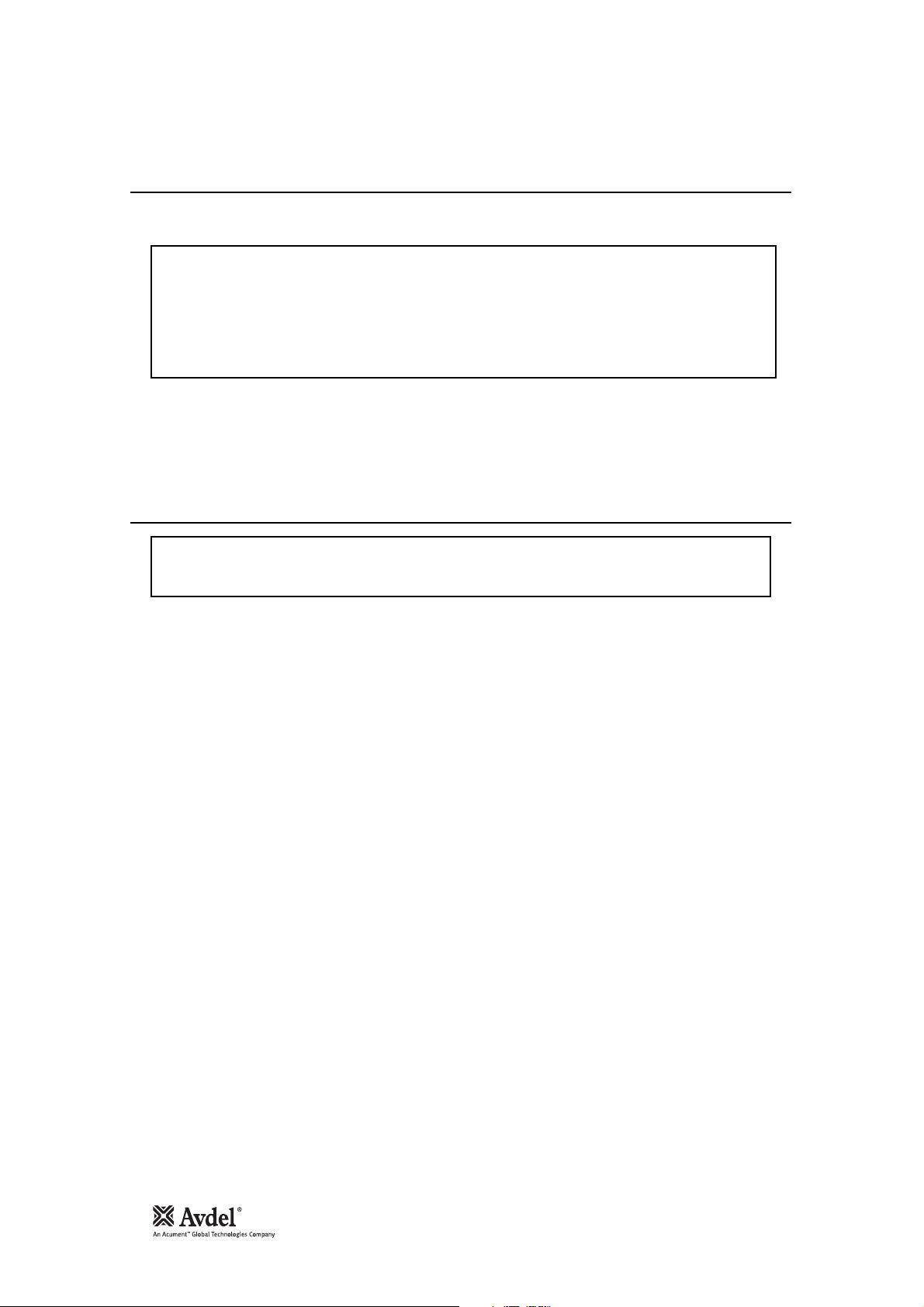
5
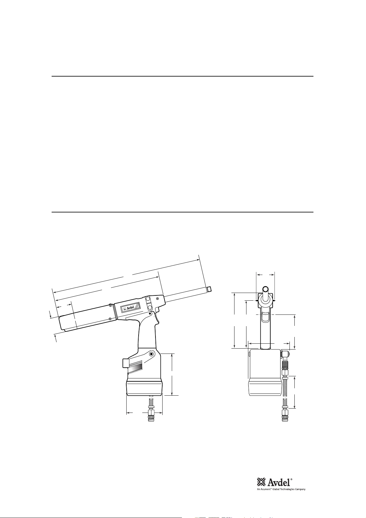
Specification for 07537 Tool
Tool Dimensions
Specifications
Air Pressure Minimum - Maximum 5-7 bar (70-100 lbf/in2)
Free Air Volume Required @ 5.1 bar /75 lbf/in
2
2.6 litres (0.09 ft3)
Stroke Minimum 28.0 mm (1.10 in)
Pull Force @ 5.5 bar /80 lbf/in
2
3.89 kN (875 lbf)
Cycle time Approximately 1 second
Noise Level Less than 70 dB(A)
Weight Tool 2.3 kg (5.06 lb)
Vibration Less than 2.5 m/s2(8 ft/s2)
Part Number 07537-00200
English
50
1.96
51
2
338
13.30
475
18.70
07537
07537
110
120
163
6.41
140
5.51
60
2.36
98
3.85
121
150
6
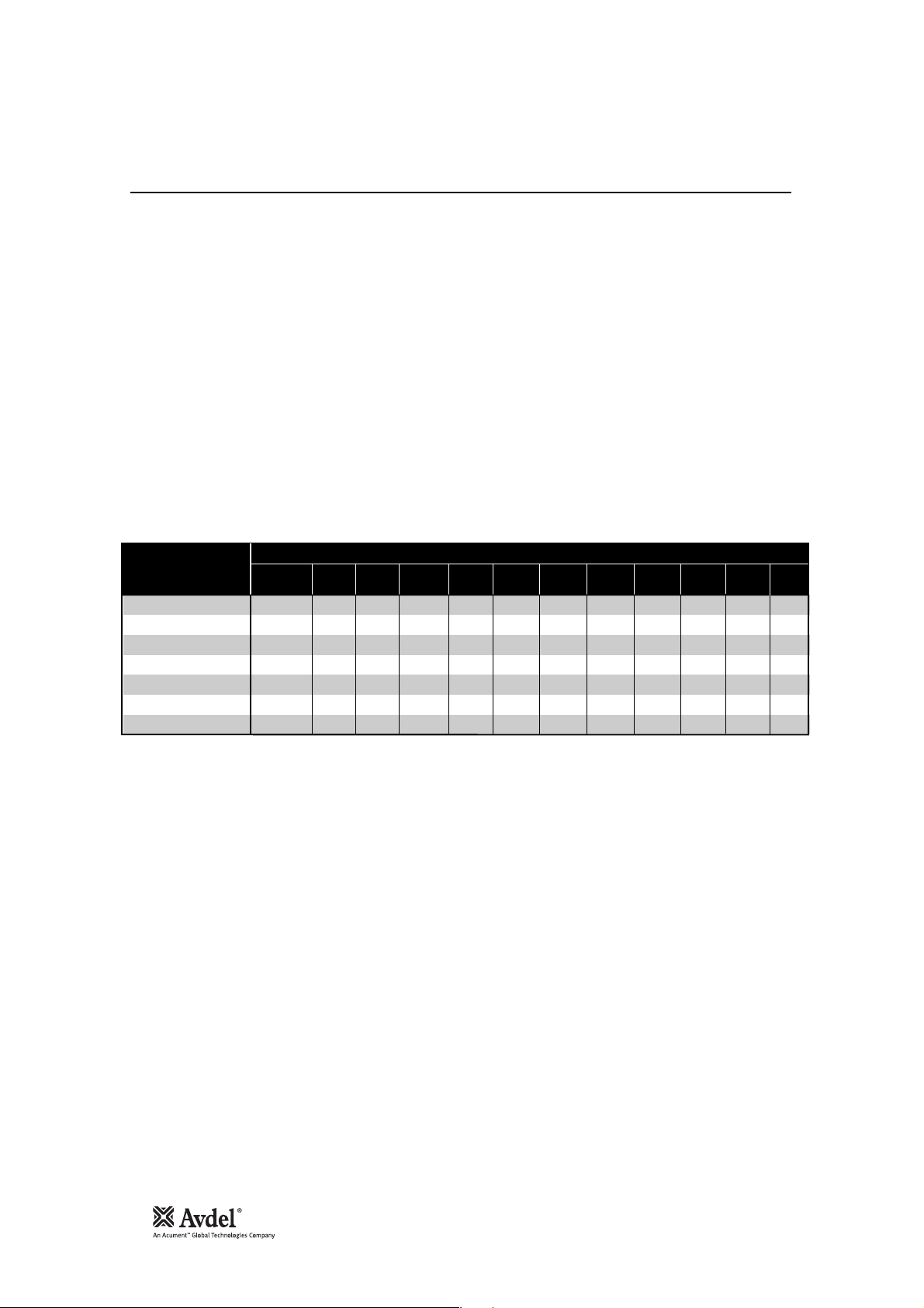
Intent of Use
The pneumatic 07537 tool is a handheld lightweight tool designed to place Avdel®speed fasteners (except 1/16” Avlug®) making it
ideal for batch or flow-line assembly in a wide variety of applications throughout all industries.
Part numbers are shown to order a complete tool but no nose equipment.
The tool part number for the 07537 model is 07537-00200. See the general assemblies on pages 26-27.
The tool will place most repetition fasteners, as shown in the table below.
The tool is used with specific nose equipment. Reference must be made to the Nose Equipment section of the manual when selecting
compatible components for the type and size of fastener used in your application (see pages 12-20). Nose jaw dimensions are shown
on page 13.
FASTENER NAME
GROVIT
AVLUG
BRIV
AVSERT
®
®
®
®
®
®
®
CHOBERT
RIVSCREW
AVTRONIC
FASTENER SIZE
3
/32"
1
/8"
5
/32"
3
●●●●●
●●●●
●●
●●●●
/16"
1
/4"
2.5mm
2.8mm
4mm3.5mm3mm
6mm
M2.5
4-40
UNC
●
● ● ● ●
●
● ●
M3
6-32
UNC
7
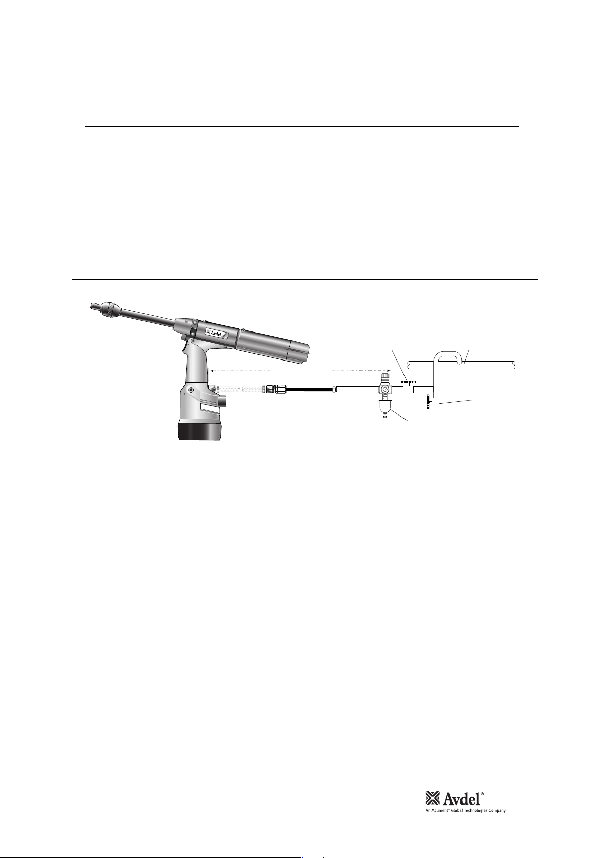
Air Supply
Putting into Service
All tools are operated with compressed air at an optimum pressure of 5.5 bar. We recommend the use of pressure regulators and
filtering systems on the main air supply. These should be fitted within 3 metres of the tool (see diagram below) to ensure maximum
tool life and minimum tool maintenance.
Air supply hoses should have a minimum working effective pressure rating of 150% of the maximum pressure produced in the system
or 10 bar, whichever is the highest. Air hoses should be oil resistant, have an abrasion resistant exterior and should be armoured
where operating conditions may result in hoses being damaged. All air hoses MUST have a minimum bore diameter of 6.4 millimetres
or
1
/4 inch.
Read servicing daily details page 21.
English
STOP COCK
(USED DURING MAINTENANCE
OF FILTER/REGULATOR UNIT)
TAKE OFF POINT
FROM
MAIN SUPPLY
3 METRES MAXIMUM
10
8
6
12
4
14
2
16
0
07537
PRESSURE REGULATOR
AND FILTER (DRAIN DAILY)
MAIN SUPPLY
DRAIN POINT
8
Mechanical Cursors
Putting into Service
MECHANICAL CURSOR
PART NO.
END PLUG
PART NO.
07271-01100
07279-05843
07279-05845
07150-00402
07159-05844
07159-05846
COLOUR
PLAIN STEEL
GOLD
SILVER
HOLE DIAMETER
(mm)
2.7
2.2
3.3
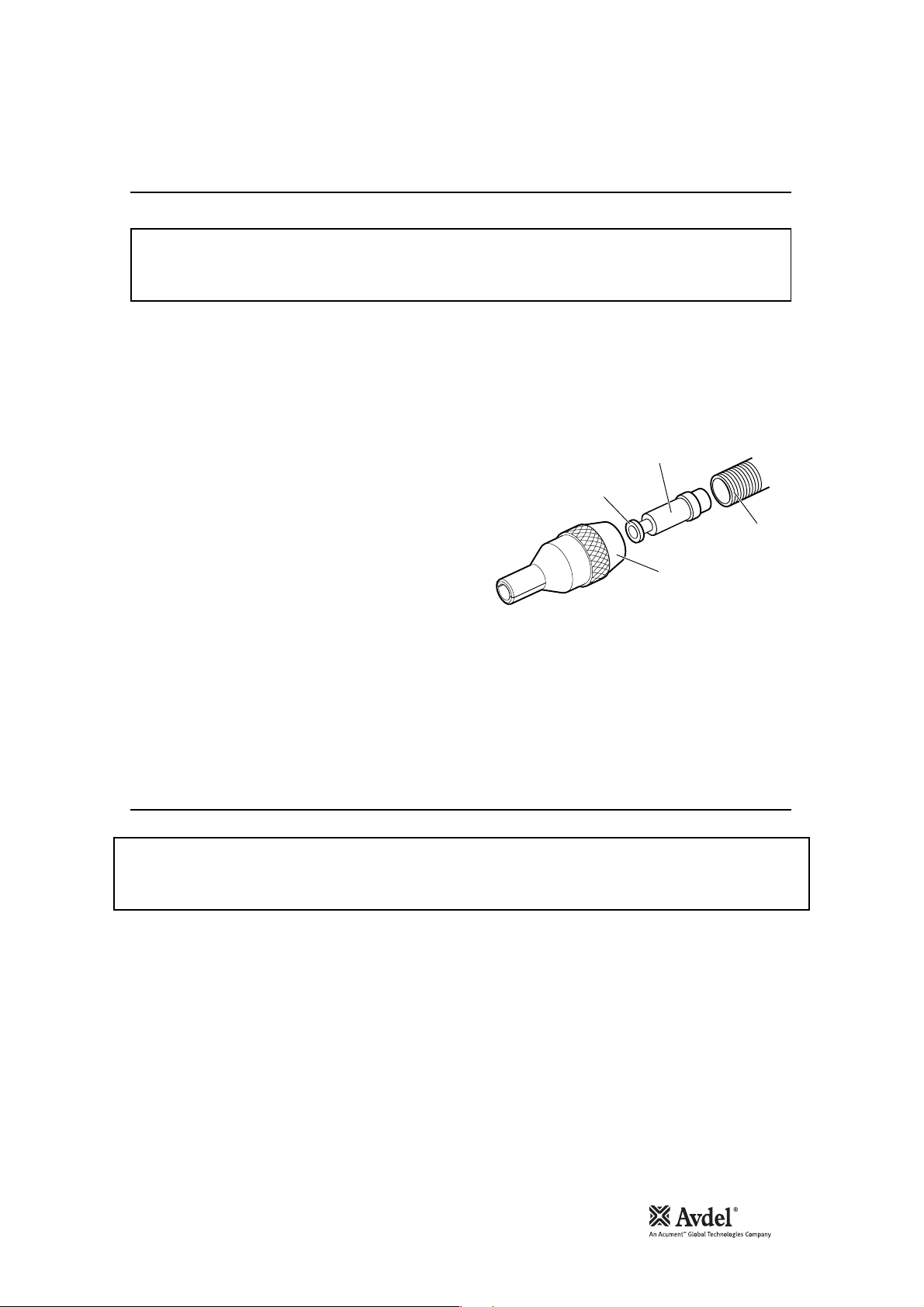
For reference there are three different mechanical cursor types:
• 07271-01100 Used for Standard mandrels and 5/32” Disposable mandrels
• 07279-05843 Used for 1/8” Disposable mandrels
• 07279-05845 Used for 3/16” Disposable mandrels
The difference in the above assemblies is the internal diameter of the End Plug.
These are colour coded see below:
END PLUG
TOOL
BARREL
CURSOR
SPRING
LOADED END
NOSE
JAWS
9
Cursor
Loading and Reloading the Tool
Putting into Service
While the cursor will be fitted the correct way round when the tool is supplied, we recommend that you check its orientation before
fitting the nose equipment. The sprung loaded, slightly concave, end of the cursor should point towards the front of the tool as shown
in the illustration.
When fitted the correct way round, the cursor will easily slide out of the barrel when a mandrel is pushed into its centre then pulled
back.
To reverse the orientation of the cursor, follow these steps:
Item numbers in bold refer to the general assembly and parts list for
the 07537-00200 on pages 26-27.
• Remove the clip 48 and slide off end cap 50.
• Using an Allen Key, remove one cap head screw 5 ensuring that
any trapped air is exhausted. remove the second cap head screw
5.
• Pull out rear plug 47.
• Pull out tail jaw piston assembly 51 together with jaws 34.
• Lift out spring 35 and jaw housing 41.
• Insert a mandrel into the hole in the rear end of barrel 44 until it protrudes through the front of the barrel, then pull out the
mandrel and cursor together through the front.
• Reassemble components in reverse order.
• Insert Mechanical Cursor Assembly 36 into the front of the barrel, correct way round.
When ordering a complete tool or system you will normally be supplied with all the nose equipment required for the fastener to be placed.
To identify nose equipment components or to select the correct elements, read the nose equipment section, on pages 12-20.
If you have been supplied with a nose jaw, mandrels and mandrel follower springs proceed with loading the tool and fitting the nose equipment
as shown overleaf.
IMPORTANT
If fitted incorrectly, the cursor will not allow feeding of the fasteners.
IMPORTANT
The procedure for loading the tool and for fitting the nose equipment to the tool is integral.
Item numbers in bold refer to the general assembly and parts list for the 07537-00200 on pages 26-27.
English
SPRING
LOADED END
CURSOR
TOOL
BARREL
NOSE
JAWS
10
Loading the Tool
Reloading the Tool
Operating Procedure
Putting into Service
• Connect the air supply to the tool.
• Open tail jaws 34 which grip the mandrel, by switching off the tail jaw switch (items 22 and 23).
• Screw selected nose jaws onto barrel 44 of the tool.
•* Insert a mandrel into the tail end of the fasteners through the paper pod.
• Slide the mandrel follower spring onto the mandrel ensuring correct orientation, as shown in the table on page 11.
• Gripping the tail end of the mandrel, tear off the paper pod from around the fasteners.
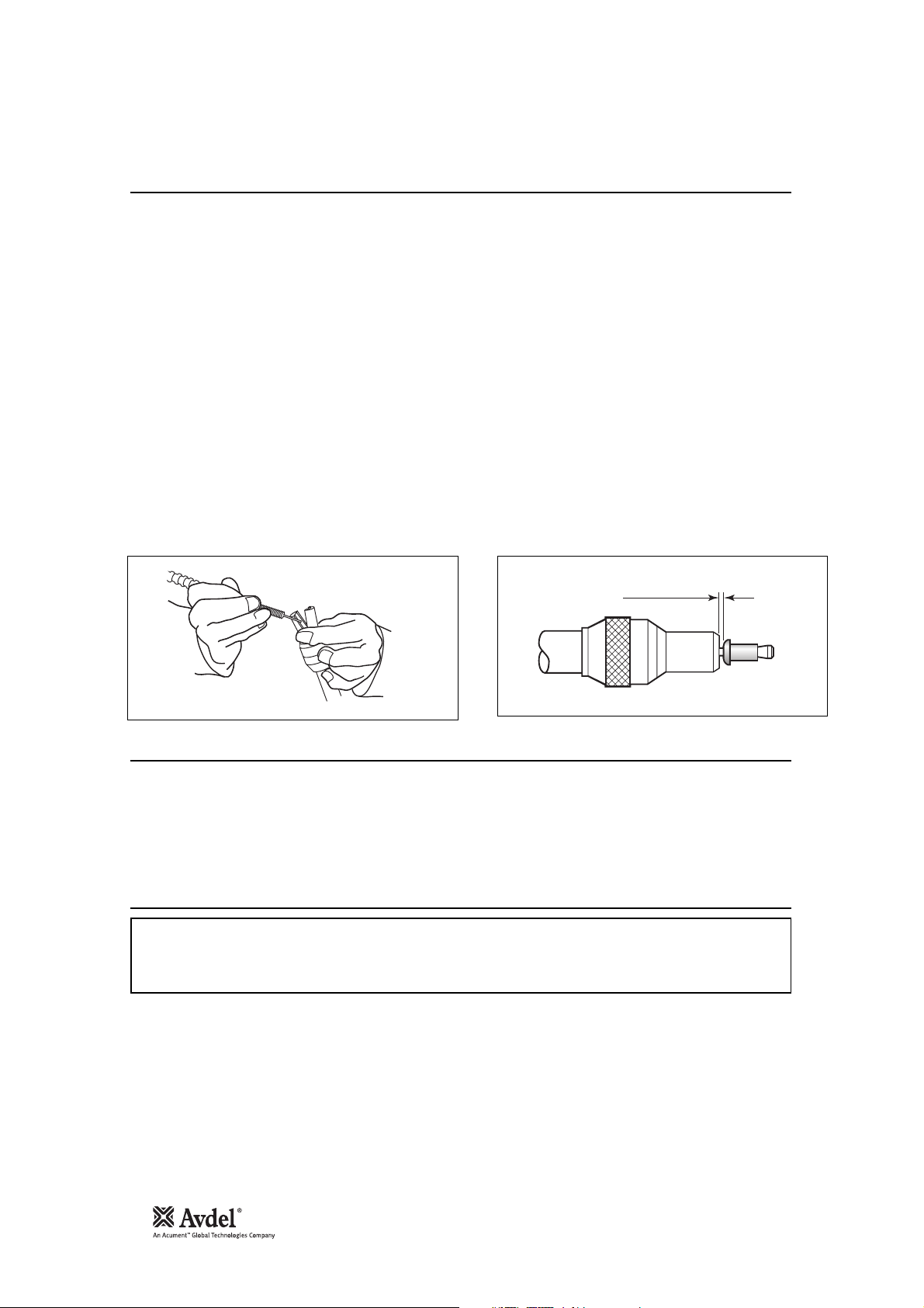
• Open the nose jaws either by rotating the outer ring on Cam operated jaws or by pushing outwards on the jaw ends, as illustrated
below left.
• Insert the previously assembled mandrel, mandrel follower spring and fasteners into the nose jaws until the first fastener to be
placed is protruding from the nose jaw.
• Close the nose jaws and adjust so that the first fastener protrudes by 1.5mm - 3mm (
1
/16” to 1/8”), as shown in the illustration
below right.
• Close the tail jaws to ensure the mandrel is gripped, by switching on the tail jaw switch (items 22 and 23).
• Push the fastener, protruding from the nose jaws, fully into the application holes ensuring that the tool is held square.
• Operate the trigger without releasing - the mandrel head is pulled through the fastener, forming the fastener into the application.
• Remove the tool.
• Release the trigger. The next fastener will be automatically presented through the nose jaws, ready for placing.
• Open tail jaws 34 of tool.
• Open the nose jaws and pull the empty mandrel and mandrel follower spring out of the tool.
• Reload the tool by following the above instructions, starting at stage •*.
IMPORTANT
You must check that the cursor orientation and the nose equipment are correct before attempting to operate the
tool.
Item numbers in bold refer to the general assembly and parts list for the 07537-00200 on pages 26-27.
1.5mm - 3mm
1
(
/16" - 1/8")
11
Putting into Service
English
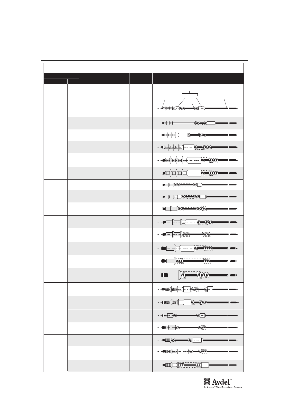
MANDREL FOLLOWER SPRINGS IDENTIFICATION AND ORIENTATION
FASTENER
(SEE NOSE EQUIPMENT SECTION)
SIZENAME
3
/32"
NOSE JAW
STANDARD TAPERED
MANDREL
SIZE
ALL
MANDREL/MANDREL FOLLOWER SPRING
AND FASTENER ASSEMBLY
MANDREL FOLLOWER SPRING
MANDREL HEAD
FERRULE
SPRING
MANDREL
®
BRIV
CHOBERT
®
AVLUG
GROVIT
CHOBERT
GROVIT
3
/32"
1
/8"
5
/32"
3
/16"
6mm
3
/32"
®
3
/32"
®
1
/8"
5
/32"
5
/32"
®
®
3
/16"
3
/16"
LIMITED ACCESS &
LIMITED ACCESS CAM OPERATED
ALL
ALL
ALL
STANDARD
ALL EXCEPT
STANDARD TAPERED,
LIMITED ACCESS
STANDARD TAPERED,
LIMITED ACCESS
ALL
ALL
ALL
ALL
ALL
ALL
ALL
ALL
ALL
ALL
EXCEPT 3rd
OVERSIZE
ALL
ALL
ALL
ALL EXCEPT
3rd
OVERSIZE
3rd
OVERSIZE
ALL EXCEPT
2nd
OVERSIZE
2nd
OVERSIZE
CHOBERT
RIVSCREW
®
AVSERT
AVTRONIC
1
/4"
®
2.8mm
3mm
®
3.5mm
4mm
2.5mm
4 x 40
UNC
3mm
6 x 32
UNC
2.5mm
®
2.8mm
2.8mm
ALL
ALL
ALL ALL
ALL
ALL
ALL
ALL EXCEPT
LIMITED ACCESS
LIMITED ACCESS
ALL
ALL
ALL
ALL
ALL
ALL
ALL
12
Nose Jaws
Nose Assemblies
IMPORTANT
To avoid complete dismantling of the tool it is essential to check the orientation of the cursor before fitting
the nose equipment to the tool. See ‘CURSOR’ section on page 9.
It is essential that the correct nose equipment is fitted to the tool to ensure both effective placing of the
fastener and SAFE operation of the tool. READ THE SAFETY INSTRUCTIONS page 4 carefully.
On speed fastening tools such as 0753 MkII type, the nose equipment always consists of three elements: a nose jaw, a mandrel and a
mandrel follower spring. All three items are matched to the fastener being placed and to the hole size in the application.
To identify the correct combination of nose equipment to fit your tool first select a nose jaw by reading the section below then read the
mandrel section to select part numbers both for the mandrel itself and for the mandrel follower spring. Mandrels and mandrel follower
springs are illustrated on page 11.
To fit the nose equipment, follow the ‘Loading the Tool’ procedure page 10.
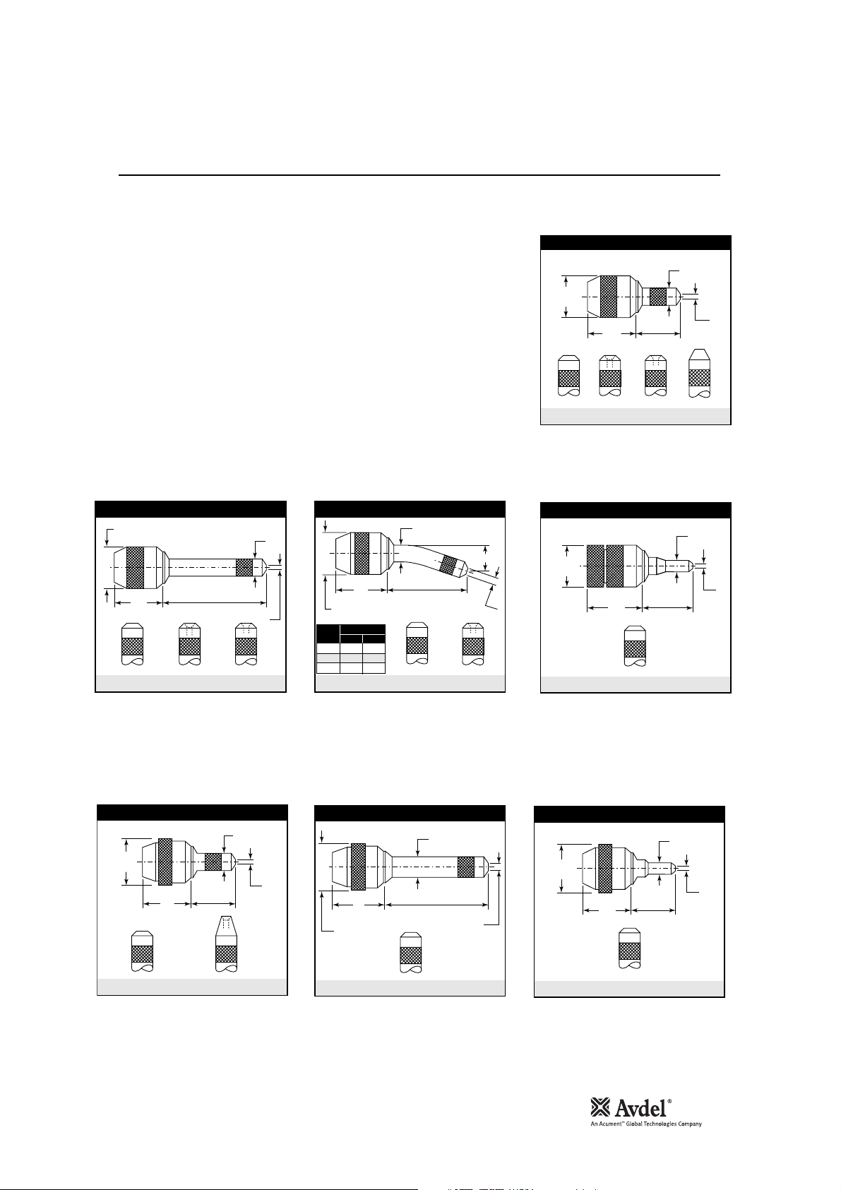
Nose Jaws can be categorised into 7 different basic shapes as illustrated opposite, even though internal dimensions will vary
according to the fastener it is intended for. Exact dimensions referring to the letters in the illustrations opposite are indicated in the
‘Nose Jaw Selection Tables’ on pages 14-15.
For a particular shape, there may be several options of end form giving access benefits or fastener placing enhancement.
Flat
• Normal end form of all nose jaws.
• Suitable on all applications with no access restrictions.
Universal
• Designed for use with universal head Chobert
®
fasteners.
• Can also be used with Briv
®
fasteners to obtain the highest possible clench. Note this reduces the maximum grip range of the
Briv®fastener by approximately 0.015” (0.4mm).
Recessed
• For use with Briv
®
fasteners ONLY.
• It gives a higher clench than a flat end form but less than a universal end form, with no reduction of the grip range of the fastener.
Tapered
• Available as shown in the ‘Nose Jaw Selection Tables’.
• Allows greater accessibility than a flat end form and places the same range.
Head Forming
• For use with Rivscrew
®
fasteners ONLY.
• Deforms the head of the fastener to achieve good clench.
IMPORTANT
The wrong nose jaw could result in an incorrectly placed fastener or incorrect clench.
13
Selecting a Nose Jaw
Nose Assemblies
Available in 4 different end forms to place all
fasteners (except Rivscrew). Suitable on
applications with no or little access restriction.
• List the name, size and material of the fastener to be placed.
• Look for this fastener in the first column of the nose jaw selection tables on page 14
if you use imperial measurements and on page 15 if you use metric units.
• Looking right across the table, take note of which nose jaws are available. ONLY
those shown are available.
• Select which is most suitable for your application by referring to the respective nose
jaw drawing. If your application has no access restriction, you should select the
standard shape with a flat end form with or without a cam.
Available as shown in NOSE JAW SELECTION TABLE.
Allows access into very restrictive applications.
Available as shown in NOSE JAW SELECTION TABLE overleaf. Equivalent functions to the Standard and Limited Access above with the
addition of a cam to ease and speed up the nose jaw opening thus the pod reloading procedure.
Available as shown in NOSE JAW SELECTION TABLE.
Allows more penetration into applications
with restricted access.
Mandrels must be curved by hand to follow
the shape of the jaw.
Available to place most of the fasteners.
Allows more penetration into applications
with no other access restriction.
Dimensions shown in bold are millimetres. Other dimensions are in inches.
English
28.6
1.125
33.5
1.32
LONG
UNIVERSALFLAT
'D'
'B'
RECESSED
'E'
1.125
RIVET
Ø
1
/8 .620 15.7
5
/32 .690 17.5
3
/16 .720 18.3
28.6
mm in.
LONG CURVED
33.5
1.32
'F'
'B'
'D'
FLAT RECESSED
STANDARD
28.6
1.125
33.5
1.32
UNIVERSALFLAT
'D'
RECESSED TAPERED
'F'
'E'
LIMITED ACCESS
20.5
0.81
41.4
1.63
FLAT
'B'
'E'
'B'
'E'
'D'
STANDARD CAM OPERATED
'B'
28.6
1.25
'D'
HEAD FORMING (HF)
FLAT
34
1.34
'E'
LONG CAM OPERATED
34
1.34
28.6
1.25
FLAT
LIMITED ACCESS CAM OPERATED
'B'
28.6
1.25
'D'
'E'
37.1
1.46
'B'
'E'
'D'
FLAT

14
Nose Jaw Selection - Imperial
Nose Assemblies
The ‘REF Nº’ column cross references with the ‘REF Nº’ columns in the mandrel section. It identifies both the mandrel and mandrel
follower spring required for a particular nose jaw with a specific fastener.
# These nose jaws are suitable for placing Chobert®rivets with a Universal Head Form. When used on the equivalent size of Briv®, the
highest possible clench is achieved. Note when using Briv
®
fasteners, the maximum grip is reduced by approximately 0.015" (0.4mm).
FASTENER
3/32" CHOBERT®
& GROVIT®
1/8" CHOBERT®
& GROVIT®
5/32" CHOBERT®
& GROVIT®
3/16" CHOBERT®
& GROVIT®
1/4" CHOBERT®
3/32" BRIV®
Brass only
1/8" BRIV®
Al. Alloy,
Brass, Steel
5/32" BRIV®
Al. Alloy,
Brass, Steel
5/32" BRIV®
St.Steel only
3/16" BRIV®
Al. Alloy,
Brass, Steel
3/16" BRIV®
St.Steel only
6mm BRIV®
Al. Alloy, Steel
3/32" AVLUG®
1/8" AVLUG®
2.5mm, 4-40 UNC
AVSERT®
3.0mm, 6-32 UNC
AVSERT®
2.5mm AVTRONIC®
2.8mm AVTRONIC®
2.8mm RIVSCREW®
3.0mm RIVSCREW®
3.5mm RIVSCREW®
4.0mm RIVSCREW®
REF.
Nº
1
STD. CAM OPERATED - FLAT
1
2
4
5
5
6
6
7
7
8
8
9
9
10
10
11
12
13
14
15
15
16
16
LONG CURVED - RECESSED
17
18
18
19
20
20
21
22
22
23
24
24
25
26
27
STD. CAM OPERATED - FLAT
27
28
29
STD. CAM OPERATED - FLAT
29
30
31
32
33
34
35
37
STD. CAM OPERATED - HF
38
STD. CAM OPERATED - HF
39
STD. CAM OPERATED - HF
40
STD. CAM OPERATED - HF
41
TYPE AND
END FORM
STANDARD - FLAT
STANDARD - TAPERED
LONG - FLAT
STANDARD - FLAT
STANDARD - TAPERED
LONG - FLAT
LONG CURVED - FLAT
STANDARD - FLAT
STANDARD - TAPERED
LONG - FLAT
LONG CURVED - FLAT
STANDARD - FLAT
STANDARD - TAPERED
LONG - FLAT
LONG CURVED - FLAT
STANDARD - FLAT
LONG - FLAT
STANDARD - TAPERED
LIMITED ACCESS
STANDARD - FLAT
STANDARD - TAPERED
LONG - RECESSED
STANDARD - FLAT
LONG - FLAT
LONG CURVED - FLAT
STANDARD - FLAT
LONG - FLAT
LONG CURVED - FLAT
STANDARD - FLAT
LONG - FLAT
LONG CURVED - FLAT
STANDARD - FLAT
LONG - FLAT
LONG CURVED - FLAT
STD. CAM OPERATED
LONG CAM OPERATED
STANDARD - FLAT
LONG CURVED - FLAT
STANDARD - FLAT
LONG CURVED - FLAT
STANDARD - FLAT
STANDARD - FLAT
STANDARD - FLAT
LONG - FLAT
STANDARD - FLAT
LONG - FLAT
NOSE JAW
PART Nº
07150-03003
07170-04500
07170-03103
07150-04003
07150-03004
07170-03104
07150-04004
07150-05004
07150-03005
07150-03105
07150-04005
07150-05005
07150-03006
07150-03106
07150-04006
07150-05006
07150-03008
07150-04008
07170-03103
07274-01000
07150-03004
07170-03104
07170-03204
07170-03304
07150-03005
07150-04005
07150-05005
07150-03005
07150-04005
07150-05005
07150-03006
07150-04006
07150-05006
07150-03006
07150-04006
07150-05006
07170-05600
07170-05700
07150-03003
07170-04500
07150-05003
07150-03004
07170-04600
07150-05004
07150-03003
07150-03004
07150-03003
07150-04003
07271-05600
07271-05900
07271-03000
07271-03000
07271-03500
07271-04000
DIMENSIONS
'D' 'E''B'
1.30
.36
1.30
.36
1.30
.36
2.30
.41
1.18
.41
1.19
.41
2.18
.41
2.12
.41
1.30
.48
1.30
.44
2.30
.48
2.23
.48
1.18
.56
1.18
.56
2.30
.56
2.21
.56
1.18
.64
2.18
.64
1.30
.36
1.07
.22
1.18
.41
1.19
.41
2.18
.41
2.12
.41
1.30
.48
2.30
.48
2.23
.48
1.30
.48
2.30
.48
2.23
.48
1.18
.56
2.30
.56
2.21
.56
1.18
.56
2.30
.56
2.21
.56
1.21
.64
2.19
.64
1.30
.36
1.30
.36
2.28
.41
1.18
.41
1.18
.41
2.12
.41
1.30
.36
1.18
.41
1.30
.36
2.30
.41
1.30
.36
2.30
.41
1.18
.41
1.18
.41
1.18
.41
1.18
.41
.16
.16
.16
.16
.20
.20
.20
.20
.24
.24
.24
.24
.33
.33
.33
.33
.39
.39
.15
.16
.20
.20
.30
.30
.24
.24
.24
.24
.24
.24
.33
.33
.33
.33
.33
.33
.52
.52
.16
.16
.16
.20
.20
.20
.16
.20
.16
.16
.16
.16
.24
.24
.24
.25
REF.
Nº
# STANDARD - UNIVERSAL
1
LTD. ACCESS CAM OPERATED
1
3
4
5
5
6
6
7
7
8
8
9
9
10
10
11
12
14
15
16
16
17
18
18
19
20
20
21
22
22
23
24
24
25
26
27
28
29
30
30
32
33
36
-
-
-
-
-
LIMITED ACCESS
LONG CURVED - FLAT
# STANDARD - UNIVERSAL
STD. CAM OPERATED - FLAT
# LONG - UNIVERSAL
LONG CAM OPERATED - FLAT
# STANDARD - UNIVERSAL
STD. CAM OPERATED - FLAT
# LONG - UNIVERSAL
LONG CAM OPERATED - FLAT
# STANDARD - UNIVERSAL
STD. CAM OPERATED - FLAT
# LONG - UNIVERSAL
LONG CAM OPERATED - FLAT
STD. CAM OPERATED - FLAT
LONG CAM OPERATED - FLAT
LTD. ACCESS CAM OPERATED
STANDARD - RECESSED
LONG CURVED - FLAT
STANDARD - RECESSED
LONG - RECESSED
LONG CURVED - RECESSED
STANDARD - RECESSED
LONG - RECESSED
LONG CURVED - RECESSED
STANDARD - RECESSED
LONG - RECESSED
LONG CURVED - RECESSED
STANDARD - RECESSED
LONG - RECESSED
LONG CURVED - RECESSED
STANDARD - FLAT
STANDARD - TAPERED
STANDARD - TAPERED
LONG CAM OPERATED - FLAT
STD. CAM OPERATED - FLAT
LTD. ACCESS CAM OPERATED
LTD. ACCESS CAM OPERATED
TYPE AND
END FORM
-
LONG - FLAT
-
LONG - FLAT
LONG - FLAT
-
LONG - FLAT
-
-
-
-
-
-
-
NOSE JAW
07150-03203
07177-03003
07274-01000
07150-05003
07150-03204
07170-04600
07150-04204
07170-05000
07150-03205
07170-04700
07150-04205
07170-05100
07150-03206
07170-04800
07150-04206
07170-05200
07170-04900
07170-05300
07177-03003
07170-03004
07150-04004
07150-05004
07170-03005
07170-03205
07170-03305
07170-03005
07170-03205
07170-03305
07170-03006
07170-03206
07170-03306
07170-03006
07170-03206
07170-03306
07170-05800
07170-05900
07150-03103
07150-04003
07170-03104
07150-04004
07170-05000
07170-04600
07271-08000
07271-08100
PART Nº
-
-
-
-
-
-
-
-
-
-
DIMENSIONS
.36
.20
.22
.41
.41
.41
.41
.41
.48
.48
.48
.48
.56
.56
.56
.56
.64
.64
.20
.41
.41
.41
.48
.48
.48
.48
.48
.48
.56
.56
.56
.56
.56
.56
.64
.64
.36
.41
.41
.41
.41
.41
.41
.40
-
-
-
-
-
'D' 'E''B'
1.33
1.18
1.07
2.28
1.22
1.18
2.22
2.18
1.35
1.30
2.35
2.30
1.24
1.18
2.39
2.30
1.18
2.18
1.18
1.20
2.18
2.12
1.32
2.30
2.23
1.32
2.30
2.23
1.20
2.30
2.21
1.20
2.30
2.21
1.21
2.19
1.30
2.30
1.19
2.18
2.18
1.18
1.18
1.18
.24
.16
.16
.16
.32
.20
.30
.20
.41
.24
.42
.24
.47
.33
.48
.33
.39
.39
.16
-
.30
.20
.20
-
.41
.41
.41
.41
.41
.41
.47
.47
.47
.47
.47
.47
.52
.52
.16
.16
-
.20
.20
.20
-
.20
.16
-
.16
-
-
-
-
-
-
-
-
-
-

15
Nose Jaw Selection - Metric
Nose Assemblies
# These nose jaws are suitable for placing Chobert®rivets with a Universal Head Form. When used on the equivalent size of Briv®, the
highest possible clench is achieved. Note that when using Briv
®
fasteners, the maximum grip is reduced by approximately 0.015" (0.4mm).
English
FASTENER
3/32" CHOBERT®
& GROVIT®
1/8" CHOBERT®
& GROVIT®
5/32" CHOBERT®
& GROVIT®
3/16" CHOBERT®
& GROVIT®
1/4" CHOBERT®
3/32" BRIV®
Brass only
1/8" BRIV®
Al. Alloy,
Brass, Steel
5/32" BRIV®
Al. Alloy,
Brass, Steel
5/32" BRIV®
St.Steel only
3/16" BRIV®
Al. Alloy,
Brass, Steel
3/16" BRIV®
St.Steel only
6mm BRIV®
Al. Alloy, Steel
3/32" AVLUG®
1/8" AVLUG®
2.5mm, 4-40 UNC
AVSERT®
3.0mm, 6-32 UNC
AVSERT®
2.5mm AVTRONIC®
2.8mm AVTRONIC®
2.8mm RIVSCREW®
3.0mm RIVSCREW®
3.5mm RIVSCREW®
4.0mm RIVSCREW®
REF.
Nº
1
STD. CAM OPERATED - FLAT
1
2
4
5
5
6
6
7
7
8
8
9
9
10
10
11
12
13
14
15
15
16
16
LONG CURVED - RECESSED
17
18
18
19
20
20
21
22
22
23
24
24
25
26
27
27
STD. CAM OPERATED - FLAT
28
29
29
STD. CAM OPERATED - FLAT
30
31
32
33
34
35
37
38
STD. CAM OPERATED - HF
39
STD. CAM OPERATED - HF
40
STD. CAM OPERATED - HF
41
STD. CAM OPERATED - HF
TYPE AND
END FORM
STANDARD - FLAT
STANDARD - TAPERED
LONG - FLAT
STANDARD - FLAT
STANDARD - TAPERED
LONG - FLAT
LONG CURVED - FLAT
STANDARD - FLAT
STANDARD - TAPERED
LONG - FLAT
LONG CURVED - FLAT
STANDARD - FLAT
STANDARD - TAPERED
LONG - FLAT
LONG CURVED - FLAT
STANDARD - FLAT
LONG - FLAT
STANDARD - TAPERED
LIMITED ACCESS
STANDARD - FLAT
STANDARD - TAPERED
LONG - RECESSED
STANDARD - FLAT
LONG - FLAT
LONG CURVED - FLAT
STANDARD - FLAT
LONG - FLAT
LONG CURVED - FLAT
STANDARD - FLAT
LONG - FLAT
LONG CURVED - FLAT
STANDARD - FLAT
LONG - FLAT
LONG CURVED - FLAT
STD. CAM OPERATED
LONG CAM OPERATED
STANDARD - FLAT
LONG CURVED - FLAT
STANDARD - FLAT
LONG CURVED - FLAT
STANDARD - FLAT
STANDARD - FLAT
STANDARD - FLAT
LONG - FLAT
STANDARD - FLAT
LONG - FLAT
NOSE JAW
PART Nº
07150-03003
07170-04500
07170-03103
07150-04003
07150-03004
07170-03104
07150-04004
07150-05004
07150-03005
07150-03105
07150-04005
07150-05005
07150-03006
07150-03106
07150-04006
07150-05006
07150-03008
07150-04008
07170-03103
07274-01000
07150-03004
07170-03104
07170-03204
07170-03304
07150-03005
07150-04005
07150-05005
07150-03005
07150-04005
07150-05005
07150-03006
07150-04006
07150-05006
07150-03006
07150-04006
07150-05006
07170-05600
07170-05700
07150-03003
07170-04500
07150-05003
07150-03004
07170-04600
07150-05004
07150-03003
07150-03004
07150-03003
07150-04003
07271-05600
07271-05900
07271-03000
07271-03000
07271-03500
07271-04000
DIMENSIONS
33.02
9.14
33.02
9.14
33.02
9.14
58.42
10.41
29.97
10.41
30.23
10.41
55.37
10.41
53.85
10.41
33.02
12.19
33.02
11.18
58.42
12.19
56.64
12.19
29.97
14.22
29.97
14.22
58.42
14.22
56.13
14.22
29.97
16.26
55.37
16.26
33.02
9.14
27.18
5.59
29.97
10.41
30.23
10.41
55.37
10.41
53.85
10.41
33.02
12.19
58.42
12.19
56.64
12.19
33.02
12.19
58.42
12.19
56.64
12.19
29.97
14.22
58.42
14.22
56.13
14.22
29.97
14.22
58.42
14.22
56.13
14.22
30.65
16.33
55.65
16.33
33.02
9.14
33.02
9.14
57.91
10.41
29.97
10.41
29.97
10.41
53.85
10.41
33.02
9.14
29.97
10.41
33.02
9.14
58.42
10.41
33.02
9.14
58.42
10.41
29.97
10.41
29.97
10.41
29.97
10.41
29.97
10.41
REF.
4.06
4.06
4.06
4.06
5.08
5.08
5.08
5.08
6.10
6.10
6.10
6.10
8.38
8.38
8.38
8.38
9.91
9.91
3.81
4.06
5.08
5.08
7.62
7.62
6.10
6.10
6.10
6.10
6.10
6.10
8.38
8.38
8.38
8.38
8.38
8.38
13.14
13.14
4.06
4.06
4.06
5.08
5.08
5.08
4.06
5.08
4.06
4.06
4.06
4.06
6.10
6.10
6.10
6.35
Nº
1
1
3
4
5
5
6
6
7
7
8
8
9
9
10
10
11
12
14
15
16
16
17
18
18
19
20
20
21
22
22
23
24
24
25
26
27
28
29
30
30
32
33
36
-
-
-
-
-
'D' 'E''B'
TYPE AND
END FORM
# STANDARD - UNIVERSAL
LTD. ACCESS CAM OPERATED
LIMITED ACCESS
LONG CURVED - FLAT
# STANDARD - UNIVERSAL
STD. CAM OPERATED - FLAT
# LONG - UNIVERSAL
LONG CAM OPERATED - FLAT
# STANDARD - UNIVERSAL
STD. CAM OPERATED - FLAT
# LONG - UNIVERSAL
LONG CAM OPERATED - FLAT
# STANDARD - UNIVERSAL
STD. CAM OPERATED - FLAT
# LONG - UNIVERSAL
LONG CAM OPERATED - FLAT
STD. CAM OPERATED - FLAT
LONG CAM OPERATED - FLAT
LTD. ACCESS CAM OPERATED
LONG CURVED - RECESSED
LONG CURVED - RECESSED
LONG CURVED - RECESSED
LONG CURVED - RECESSED
LONG CAM OPERATED - FLAT
STD. CAM OPERATED - FLAT
LTD. ACCESS CAM OPERATED
LTD. ACCESS CAM OPERATED
-
STANDARD - RECESSED
LONG - FLAT
LONG CURVED - FLAT
-
STANDARD - RECESSED
LONG - RECESSED
STANDARD - RECESSED
LONG - RECESSED
STANDARD - RECESSED
LONG - RECESSED
STANDARD - RECESSED
LONG - RECESSED
STANDARD - FLAT
LONG - FLAT
STANDARD - TAPERED
LONG - FLAT
-
STANDARD - TAPERED
LONG - FLAT
-
-
-
-
-
-
-
NOSE JAW
07150-03203
07177-03003
07274-01000
07150-05003
07150-03204
07170-04600
07150-04204
07170-05000
07150-03205
07170-04700
07150-04205
07170-05100
07150-03206
07170-04800
07150-04206
07170-05200
07170-04900
07170-05300
07177-03003
07170-03004
07150-04004
07150-05004
07170-03005
07170-03205
07170-03305
07170-03005
07170-03205
07170-03305
07170-03006
07170-03206
07170-03306
07170-03006
07170-03206
07170-03306
07170-05800
07170-05900
07150-03103
07150-04003
07170-03104
07150-04004
07170-05000
07170-04600
07271-08000
07271-08100
PART Nº
-
-
-
-
-
-
-
-
-
-
DIMENSIONS
33.78
9.14
29.97
5.08
27.18
5.59
57.91
10.41
30.99
10.41
29.97
10.41
56.39
10.41
55.37
10.41
34.29
12.19
33.02
12.19
59.69
12.19
58.42
12.19
31.50
14.22
29.97
14.22
60.71
14.22
58.42
14.22
29.97
16.26
55.37
16.26
29.97
5.08
-
30.48
10.41
55.37
10.41
53.85
10.41
-
33.53
12.19
58.42
12.19
56.64
12.19
33.53
12.19
58.42
12.19
56.64
12.19
30.48
14.22
58.42
14.22
56.13
14.22
30.48
14.22
58.42
14.22
56.13
14.22
30.65
16.33
55.65
16.33
33.02
9.14
58.42
10.41
-
30.23
10.41
55.37
10.41
55.37
10.41
-
29.97
10.41
29.97
10.41
-
29.97
10.16
-
-
-
-
-
'D' 'E''B'
6.10
4.06
4.06
4.06
8.13
5.08
7.62
5.08
10.41
6.10
10.67
6.10
11.94
8.38
12.19
8.38
9.91
9.91
4.06
-
-
7.62
5.08
5.08
-
-
10.41
10.41
10.41
10.41
10.41
10.41
11.94
11.94
11.94
11.94
11.94
11.94
13.14
13.14
4.06
4.06
-
-
5.08
5.08
5.08
-
-
5.08
4.06
-
-
4.06
-
-
-
-
-
-
-
-
-
-
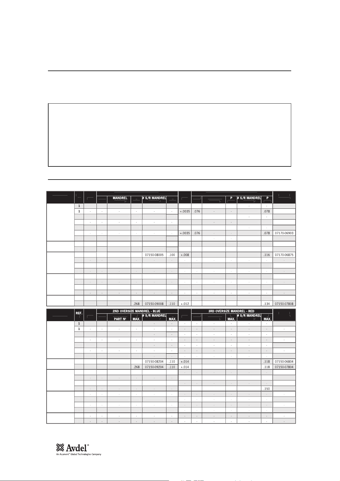
16
Mandrels and Mandrel Follower Springs
Chobert
®
and Grovit®- Imperial
Nose Assemblies
Mandrels and mandrel follower springs, illustrated on page 11 need to be selected to suit the fastener type and size as well as the size
of the hole in the application. Use of the wrong mandrel could increase the risk of breakage and the wear of the mandrel head.
Feeding problems could occur if the wrong mandrel follower spring is used.
For mandrel or mandrel follower spring selection, follow instructions on page 18.
IMPORTANT
READ THE SAFETY INSTRUCTIONS page 4 carefully.
While a small amount of wear and marking will naturally occur through normal and correct use of mandrels, they
must be regularly examined for excessive wear and marking, with particular attention to the head diameter, the
tail jaw gripping area of the shank or heavy pitting of the shank and any mandrel distortion. Mandrels which fail
during use could forcibly exit the tool. It is the customer’s responsibility to ensure that mandrels are replaced
before any excessive levels of wear and always before the maximum recommended number of placings.
Contact your Avdel UK Limited representative who will let you know what that figure is by measuring the broach
load of your application with our calibrated measuring tool. These tools can also be purchased under part
number 07900-09080, supplied with all necessary information for testing.
R
S
G
S
N
E
SIZE
OW
T
®
& GROVIT
®
T
®
& GROVIT
®
T
®
& GROVIT
®
T
®
& GROVIT
®
T
®
66
66
66
66
6
6
68
1
1
1
1
090
090
00
02
02
0
07150-06003
07150-06003
07150-06003
07150-07003
07150-0600
07150-0700
07150-06005
07150-07005
07150-06006
07150-07006
07150-06008
07150-07008
07150-08003
07150-08003
07150-08003
07150-09003
07150-08004
07150-09004
07150-09005
07150-08006
07150-09006
07150-08008
C.
C.
C.
C.
C.
C.
C.
C.
C.
C.
C.
C.
Ø
5
5
5
5
088
088
07
07
32
32
84
84
E
SIZE
37
37
84
84
0
0
330
330
8
8
098
098
6
30
30
34
07150-06303
07150-06303
07150-06303
07150-06104
07150-07104
07150-06105
07150-07105
07150-06106
07150-07106
07150-06108
07150-07108
07150-08103
07150-08103
07150-08103
07150-09103
07150-08104
07150-09104
07150-08105
07150-09105
07150-08106
07150-09106
07150-08108
07150-09108
5
5
0035
5
0035
004
004
008
4
4
2
Ø
4
4
6
4
6
092
092
5
5
6
6
96
96
07150-06803
07150-06803
0
06873
0
06873
0
06903
07150-07803
07150-06804
07150-07804
0
5
0
06876
0
6
07150-06808
R
N
S
G
N
E
E
T
®
& GROVIT
®
T
®
& GROVIT
®
T
®
& GROVIT
®
T
®
& GROVIT
®
T
®
85
85
85
85
68
0
0
2
2
30
30
50
50
07150-06103
07150-06103
07150-06103
07150-07103
07150-0620
07150-0720
07150-06205
07150-07205
07150-06206
07150-07206
07150-08205
07150-09205
07150-08206
07150-09206
0035
0035
0035
0035
0
0
5
5
4
4
Ø
6
6
6
6
098
098
56
56
E
E
88
88
2
2
50
07150-06304
07150-07304
07150-06305
07150-07305
07150-08304
07150-09304
07150-08305
07150-09305
5
5
Ø
02
02
32
32
07150-06803
0
06873
0
06903
07150-07803
0
06875
07150-06805
0
5
07150-07805
07150-06806
07150-07806
3
3
5
6
8
8
9
9
0
0
3
3
5
6
8
8
9
9
0
0
1
2
# S/R: Short Reach Mandrel. See page 18-19 for explanation.
FASTENE
HOL
AS RE
.072
TANDARD MANDREL - GREE
.1
HOL
.07
+.001
1ST OVERSIZE MANDREL - YELL
.07
PRIN
3/32" CHOBER
1/8" CHOBER
5/32" CHOBER
3/16" CHOBER
1/4" CHOBER
FASTENE
3/32" CHOBER
1/8" CHOBER
5/32" CHOBER
AS RE
.072
AS RE
.072
AS RE
.072
AS RE
.
AS RE
.
AS RE
.1
AS RE
.1
AS RE
.1
AS RE
AS RE
AS RE
HOL
SIZ
+.
+.
+.
+.
+.01
+.01
+.01
+.01
.1
.1
.1
.07
.07
.07
.07
.
.
1
1
1
1
.1
.1
.1
.21
4
.21
4
.2
.1
.1
.1
.1
.2
4
4
.32
.32
.07
+.001
.07
+.
+.001
+.
+.
+.
+.
+.01
+.01
+.01
HOL
SIZ
+.02
+.02
.07
.07
.07
.
.
.11
.11
.14
.14
.1
.1
.1
.1
.1
.1
.2
.2
.2
.2
.32
.32
.
.
.2
.2
.37
.37
.07
.07
.
.
.1
.1
.1
.11
.1
.1
.07
.07
.
.
.11
.1
.1
.1
.1
7170-
7170-
7170-
7170-0787
7170-
7170-0787
PRIN
PART
7170-
7170-
7170-
7170-0787
3/16" CHOBER
1/4" CHOBER
+.02
+.02
.1
.1
1
1
.37
.37
.1
.1
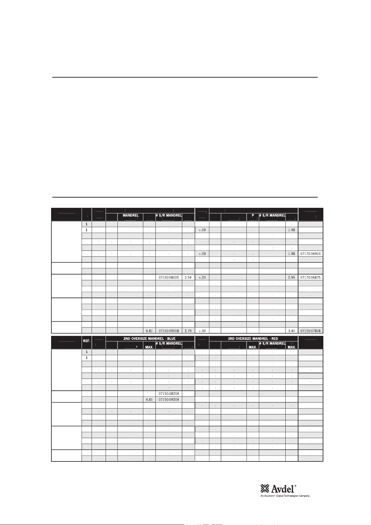
17
Chobert®and Grovit®- Metric
Nose Assemblies
Tables below left and right and over the next four pages list part numbers of all mandrels and mandrel follower springs available per
fastener or group of fasteners, i.e. for Chobert
®
and Grovit®on these pages.
While fastener sizes are always shown in their specified units, each table has been produced twice to offer dimensions in imperial units
on the left-hand page then in metric units on the right-hand page. These 'Mandrel Selection' tables cross-reference with the 'Nose Jaw
Selection' tables on pages 14-15 through the ‘Ref. Nº’ column.
It is the diameter of the head at the end of a mandrel which when pulled through controls the expansion of the fastener body.
While there are different head shapes to suit different types of fasteners (see illustration on page 19), progressive head sizes are
needed to reflect manufacturing tolerances on the diameter of the hole in your application so that the fastener always expands
sufficiently to fill the hole.
Too large a mandrel head would overstress the mandrel and mandrels which fail during use could forcibly exit the tool.
Selection tables are arranged into four 'mandrel size' sections, ranging from 'standard’ to '3rd oversize', each being colour coded as
per the end of the mandrel heads themselves.
R
3
3
5
6
8
8
9
9
0
0
S
G
S
E
SIZE
OW
T
®
& GROVIT
®
T
®
& GROVIT
®
T
®
& GROVIT
®
T
®
& GROVIT
®
T
®
5.49
5.49
6.20
6.20
6.27
6.27
6.81
80
80
80
80
9
9
54
59
59
9
07150-06003
07150-06003
07150-06003
07150-07003
07150-06004
07150-07004
07150-06005
07150-07005
07150-06006
07150-07006
07150-06008
07150-07008
07150-08003
07150-08003
07150-08003
07150-09003
07150-08004
07150-09004
07150-09005
07150-08006
07150-09006
07150-08008
C.
C.
C.
C.
C.
C.
C.
C.
C.
C.
C.AS
C.
Ø
84
84
84
84
3.35
3.35
674.67
E
SIZE
6.02
6.02
8.13
8.13
8.38
8.38
98
98
9
9
95
3.30
3.30
3.40
07150-06303
07150-06303
07150-06303
07150-06104
07150-07104
07150-06105
07150-07105
07150-06106
07150-07106
07150-06108
07150-07108
07150-08103
07150-08103
07150-08103
07150-09103
07150-08104
07150-09104
07150-08105
07150-09105
07150-08106
07150-09106
07150-08108
07150-09108
04
04
09
04
09
0
0
0
35
35
30
Ø
881.93
88
93
88
93
93
34
34
92
92
3.71
3.71
984.98
07150-06803
07150-06803
0
06873
0
06873
0
06903
07150-07803
07150-06804
07150-07804
0
5
0
06876
0
6
07150-06808
R
3
3
5
6
8
8
9
9
0
0
S
G
N
E
E
T
®
& GROVIT
®
T
®
& GROVIT
®
T
®
& GROVIT
®
T
®
& GROVIT
®
T
®
0
0
0
0
6.81
8.13
8.13
9.45
9.45
.
9
9
3.30
3.30
3.81
3.81
N
07150-06103
07150-06103
07150-06103
07150-07103
07150-06204
07150-07204
07150-06205
07150-07205
07150-06206
07150-07206
N
07150-08205
07150-09205
07150-08206
07150-09206
09
09
09
09
5
5
38
38
60
60
Ø
93
93
93
93
9
9
3.10
3.10
3.96
3.96
E
E
3
9.45
9.45
3.00
3.00
3.81
3.81
N
07150-06304
07150-07304
07150-06305
07150-07305
N
07150-08304
07150-09304
07150-08305
07150-09305
35
35
63
63
Ø
59
59
3.35
3.35
07150-06803
0
06873
0
06903
07150-07803
07150-0680
07150-0780
0
06875
07150-06805
0
5
07150-07805
07150-06806
07150-07806
N
# S/R: Short Reach Mandrel. See page 18-19 for explanation.
English
FASTENE
3/32" CHOBER
1/8" CHOBER
5/32" CHOBER
HOL
AS RE
AS RE
AS RE
AS RE
AS RE
AS RE
AS RE
AS RE
1.
1.
1.
1.
TANDARD MANDREL - GREEN
HOL
1.
+.
1.
+.
+.
1.
+.
1.
+.
2.2
+.1
2.2
+.1
2.
+.2
1ST OVERSIZE MANDREL - YELL
1.
1.
1.
1.
1.
1.
2.
2.
2.
2.
1.
1.
2.4
2.4
2.
PRIN
7170-
7170-
7170-
7170-0787
3/16" CHOBER
1/4" CHOBER
FASTENE
3/32" CHOBER
1/8" CHOBER
5/32" CHOBER
3/16" CHOBER
1/4" CHOBER
AS RE
AS RE
1
1
AS RE
4.
RE
HOL
SIZ
+.
+.
+.
+.
+.2
+.2
+.
+.
+.
1
1
+.
PART
1.
1.
1.
1.
2.4
2.4
PART
4.7
4.7
4.7
4.7
2.
2.
2.7
MAX
2.7
2.7
+.
+.
+.
HOL
SIZ
+.
+.
+.
+.
7170-
7170-0787
4.
PRIN
PART
2.
2.
7.32
7.
PART
2
PART
7170-
7170-
4
4
7170-
7170-0787

18
Briv®- Imperial
Nose Assemblies
For mandrel or mandrel follower spring selection, follow instructions above.
To find the correct part number of a mandrel for a particular application, read the instructions below after you have gathered the following
information as per example alongside. Answers for the example are shown in
grey italic.
FASTENER NAME
example Chobert
®
FASTENER SIZE
1
/8”
DATASHEET
Series 1125
APPLICATION HOLE SIZE
0.1335”
CLEARANCE BEHIND APPLICATION
Infinite
‘REF.Nº’ FROM NOSE JAW SELECTION TABLE
5 (standard flat)
• Subtract the minimum hole size recommended (AS REC.) in the fastener datasheet from the actual application hole size.
-example:
0.005.
• Turn to the page with the ‘Mandrel Selection’ table for your fastener, selecting either the imperial or the metric dimensions table
(pages 16-20).
-example: page 16.
• Staring with the ‘Standard Mandrel - Green’ section, find your fastener size in the left-hand column.
-example 1/8” Chobert®& Grovit®.
• If you selected a nose jaw which place you fastener, you should now be able to find a line within your fastener section with the same ‘Ref
No.’ as that from the ‘Nose Jaw Selection’ table.
-example: 5.
This is your line ‘Ref. No.’ in which you will find both your mandrel and
mandrel follower spring part number. This line continues into the second half of the table for the ‘2nd’ and ‘3rd’ oversize mandrels.
• Scan along the line to the ‘hole size’ columns and select which ever is the nearest or equal to the figure calculated in step one. You may
now read the mandrel part number next to the ‘hole size’.
-example: 07150-06104
• For Chobert
®
and Grovit®only, most mandrels are also available in a ‘short reach’ version (see illustration on page 19). Short reach
mandrels are used to minimise the possibility of the mandrel head contacting an obstruction. This would result in the underside of the
fastener head not seating properly on the application surface, causing a lack on clench in the joint.
• Whichever size mandrel you settle on, you will also need to check the ‘P’ figure against that mandrel is adequate. ‘P’ is the clearance
required for the mandrel head at the back of the application IN ADDITION to the length of the fastener protruding through the application,
as shown in the illustration on page 19.
• You may now read the corresponding mandrel follower spring part number in the right-hand column of the table.
-example: 07150-
06804.
In all cases, satisfactory clenching of the joint should be assessed particularly if the size of the hole in your application is very close to the
next oversize hole condition, when it will be safe to select the greater size of mandrel to obtain a higher clench. REMEMBER that this will
increase the broach load and reduce the mandrel life.
FASTENER
3/32" BRIV®
Brass only
1/8" BRIV®
Al. Alloy,
Brass, Steel
5/32" BRIV®
Al. Alloy,
Brass, Steel
5/32" BRIV®
St.Steel only
3/16" BRIV®
Al. Alloy,
Brass, Steel
3/16" BRIV®
St.Steel only
6mm BRIV®
Al. Alloy, Steel
FASTENER
3/32" BRIV®
Brass only
1/8" BRIV®
Al. Alloy,
Brass, Steel
5/32" BRIV®
Al. Alloy,
Brass, Steel
5/32" BRIV®
St.Steel only
3/16" BRIV®
Al. Alloy,
Brass, Steel
3/16" BRIV®
St.Steel only
6mm BRIV®
Al. Alloy, Steel
REF.
Nº
13
14
15
16
17
18
19
20
21
22
23
24
25
26
REF.
Nº
13
14
15
16
17
18
19
20
21
22
23
24
25
26
HOLE
SIZE
AS REC.
AS REC.
AS REC.
AS REC.
AS REC.
AS REC.
AS REC.
AS REC.
AS REC.
AS REC.
AS REC.
AS REC.
AS REC
AS REC
HOLE
SIZE
+.008
+.008
+.010
+.010
+.010
+.010
-
+.010
+.010
-
+.010
+.010
STANDARD MANDREL - GREEN
HEAD
Ø
.072
.072
.092
.092
.110
.110
.120
.120
.141
.141
.153
.153
.179
.179
HEAD
Ø
.079
.079
.102
.102
.120
.120
.151
.151
.189
.189
-
-
-
-
MANDREL
PART Nº
07150-06013
07150-06013
07271-06414
07271-07414
07150-06015
07150-07015
07170-06805
07170-07805
07150-06016
07150-07016
07170-06806
07170-07806
07150-06018
07150-07018
2ND OVERSIZE MANDREL - BLUE
MANDREL
PART Nº
07150-06213
07150-06213
07271-06614
07271-07614
07150-06215
07150-07215
07150-06216
07150-07216
07150-06218
07150-07218
HOLE
P
SIZE
MAX.
.119
+.004
.119
+.004
.120
+.005
.120
+.005
.136
+.005
.136
+.005
.126
+.005
.126
+.005
.157
+.005
.157
+.005
.150
+.005
.150
+.005
.165
+.005
.165
+.005
HOLE
P
SIZE
MAX.
.126
-
.126
-
.133
-
.133
-
.149
-
.149
-
.170
.170
.177
.177
-
-
-
+.012
+.012
-
-
-
-
-
-
-
-
-
-
1ST OVERSIZE MANDREL - YELLOW
HEAD
Ø
.076
.076
.097
.097
.115
.115
.125
.125
.146
.146
.158
.158
.184
.184
HEAD
Ø
-
-
-
-
-
-
-
.153
.153
-
-
-
-
MANDREL
PART Nº
07150-06113
07150-06113
07271-06514
07271-07514
07150-06115
07150-07115
07170-06825
07170-07825
07150-06116
07150-07116
07170-06826
07170-07826
07150-06118
07150-07118
3RD OVERSIZE MANDREL - RED
MANDREL
PART Nº
-
-
-
-
-
-
-
07150-06316
07150-07316
-
-
-
-
P
MAX.
.123
07170-06873
.123
07170-06903
.126
07150-06814
.126
07150-07814
.142
07170-06875
.142
07170-07875
.132
07170-06875
.132
07170-07875
.164
07170-06876
.164
07170-07876
.156
07170-06876
.156
07170-07876
.171
07150-06846
.171
07150-07846
P
MAX.
-
07170-06873
-
07170-06903
-
07150-06814
-
07150-07814
-
07170-06875
-
07170-07875
-
-
.173
07170-06876
.173
07170-07876
-
-
-
07150-06846
-
01750-07846
SPRING
PART Nº
SPRING
PART Nº
-
-
-
-

19
Mandrel Head Types and ‘P’ Length
Briv
®
- Metric
Nose Assemblies
Mandrels for stainless steel Briv®are easily identifiable by a ‘V’ cut in the end of the mandrel heads.
When using curved nose jaws, mandrels have to be bent by hand to match the curvature of the nose jaw, thus ensuring good feed of
fasteners.
English
CHOBERT®, GROVIT®,
AVSERT®, AVTRONIC®
P
P
SHORT REACH
(CHOBERT® &
GROVIT® ONLY)
P P
BRIV®
AVLUG®
HOLE
SIZE
+.10
+.10
+.13
+.13
+.13
+.13
+.13
+.13
+.13
+.13
+.13
+.13
+.13
+.13
HOLE
SIZE
-
-
-
-
-
-
-
+.30
+.30
-
-
-
-
1ST OVERSIZE MANDREL - YELLOW
HEAD
Ø
1.93
1.93
2.46
2.46
2.92
2.92
3.18
3.18
3.71
3.71
4.01
4.01
4.67
4.67
HEAD
Ø
-
-
-
-
-
-
-
-
3.85
3.85
-
-
-
-
MANDREL
PART Nº
07150-06113
07150-06113
07271-06514
07271-07514
07150-06115
07150-07115
07170-06825
07170-07825
07150-06116
07150-07116
07170-06826
07170-07826
07150-06118
07150-07118
3RD OVERSIZE MANDREL - RED
MANDREL
PART Nº
-
-
-
-
-
-
-
07150-06316
07150-07316
-
-
-
-
P
MAX.
3.12
3.12
3.20
3.20
3.61
3.61
3.35
3.35
4.17
4.17
3.96
3.96
4.34
4.34
P
MAX.
4.39
4.39
P
-
-
-
-
-
-
-
-
-
-
-
-
RIVSCREW®
FASTENER
2.4mm BRIV®
Brass only
3.2mm BRIV®
Al. Alloy,
Brass, Steel
4.0mm BRIV®
Al. Alloy,
Brass, Steel
4.0mm BRIV®
St.Steel only
4.8mm BRIV®
Al. Alloy,
Brass, Steel
4.8mm BRIV®
St.Steel only
6mm BRIV®
Al. Alloy, Steel
FASTENER
2.4mm BRIV®
Brass only
3.2mm BRIV®
Al. Alloy,
Brass, Steel
4.0mm BRIV®
Al. Alloy,
Brass, Steel
4.0mm BRIV®
St.Steel only
4.8mm BRIV®
Al. Alloy,
Brass, Steel
4.8mm BRIV®
St.Steel only
6mm BRIV®
Al. Alloy, Steel
BRIV®
REF.
Nº
13
14
15
16
17
18
19
20
21
22
23
24
25
26
REF.
Nº
13
14
15
16
17
18
19
20
21
22
23
24
25
26
HOLE
SIZE
AS REC.
AS REC.
AS REC.
AS REC.
AS REC.
AS REC.
AS REC.
AS REC.
AS REC.
AS REC.
AS REC.
AS REC.
AS REC
AS REC
HOLE
SIZE
+.20
+.20
+.25
+.25
+.25
+.25
-
+.25
+.25
-
+.25
+.25
STANDARD MANDREL - GREEN
HEAD
Ø
1.83
1.83
2.34
2.34
2.79
2.79
3.05
3.05
3.58
3.58
3.89
3.89
4.54
4.54
HEAD
Ø
2.01
2.01
2.59
2.59
3.05
3.05
3.84
3.84
4.79
4.79
-
-
-
-
MANDREL
PART Nº
07150-06013
07150-06013
07271-06414
07271-07414
07150-06015
07150-07015
07170-06805
07170-07805
07150-06016
07150-07016
07170-06806
07170-07806
07150-06018
07150-07018
2ND OVERSIZE MANDREL - BLUE
MANDREL
PART Nº
07150-06213
07150-06213
07271-06614
07271-07614
07150-06215
07150-07215
07150-06216
07150-07216
07150-06218
07150-07218
(STAINLESS STEEL)
P
P
MAX.
3.02
3.02
3.05
3.05
3.45
3.45
3.20
3.20
3.99
3.99
3.81
3.81
4.18
4.18
P
MAX.
3.20
3.20
3.38
3.38
3.78
3.78
-
-
-
-
-
-
4.32
4.32
-
-
4.49
4.49
SPRING
PART Nº
07170-06873
07170-06903
07150-06814
07150-07814
07170-06875
07170-07875
07170-06875
07170-07875
07170-06876
07170-07876
07170-06876
07170-07876
07150-06846
07150-07846
SPRING
PART Nº
07170-06873
07170-06903
07150-06814
07150-07814
07170-06875
07170-07875
-
07170-06876
07170-07876
-
07150-06846
07150-07846

20
Avlug®, Avsert®, Avtronic®and Rivscrew®- Imperial and Metric
Nose Assemblies
For mandrel or mandrel follower spring selection, follow instructions on page 18.
FASTENER
3/32" AVLUG®
1/8" AVLUG®
2.5mm, 4-40 UNC
AVSERT®
3.0mm, 6-32 UNC
AVSERT®
2.5mm AVTRONIC®
2.8mm AVTRONIC®
2.8mm RIVSCREW®
3.0mm RIVSCREW®
3.5mm RIVSCREW®
4.0mm RIVSCREW®
* These Dimensions are Across Flats
FASTENER
3/32" AVLUG®
1/8" AVLUG®
2.5mm, 4-40 UNC
AVSERT®
3.0mm, 6-32 UNC
AVSERT®
2.5mm AVTRONIC®
2.8mm AVTRONIC®
2.8mm RIVSCREW®
3.0mm RIVSCREW®
3.5mm RIVSCREW®
4.0mm RIVSCREW®
FASTENER
3/32" AVLUG®
1/8" AVLUG®
2.5mm, 4-40 UNC
AVSERT®
3.0mm, 6-32 UNC
AVSERT®
2.5mm AVTRONIC®
2.8mm AVTRONIC®
2.8mm RIVSCREW®
3.0mm RIVSCREW®
3.5mm RIVSCREW®
4.0mm RIVSCREW®
* These Dimensions are Across Flats
FASTENER
3/32" AVLUG®
1/8" AVLUG®
2.5mm, 4-40 UNC
AVSERT®
3.0mm, 6-32 UNC
AVSERT®
2.5mm AVTRONIC®
2.8mm AVTRONIC®
2.8mm RIVSCREW®
3.0mm RIVSCREW®
3.5mm RIVSCREW®
4.0mm RIVSCREW®
REF.
27
28
29
30
31
32
33
34
35
36
37
38
39
40
41
REF.
Nº
27
28
29
30
31
32
33
34
35
36
37
38
39
40
41
LINE
Nº
27
28
29
30
31
32
33
34
35
36
37
38
39
40
41
LINE
Nº
27
28
29
30
31
32
33
34
35
36
37
38
39
40
41
HOLE
Nº
SIZE
AS REC.
AS REC.
AS REC.
AS REC.
AS REC.
AS REC.
AS REC.
AS REC.
AS REC.
AS REC.
AS REC.
AS REC.
AS REC.
AS REC.
AS REC.
HOLE
SIZE
-
-
-
-
-
+.006
+.006
+.006
+.006
+.006
-
-
-
-
HOLE
SIZE
AS REC.
AS REC.
AS REC.
AS REC.
AS REC.
AS REC.
AS REC.
AS REC.
AS REC.
AS REC.
AS REC.
AS REC
AS REC.
AS REC.
AS REC.
HOLE
SIZE
-
-
-
-
-
+.15
+.15
+.15
+.15
+.15
-
-
-
-
STANDARD MANDREL - GREEN
HEAD
Ø
.076
.076
.098
.098
.0725
.088
.070
.070
.079
.079
.079
* .065
* .065
* .0825
* .103
HEAD
Ø
-
-
-
-
-
.076
.076
.085
.085
.085
-
-
-
-
HEAD
Ø
1.93
1.93
2.49
2.49
1.84
2.24
1.78
1.78
2.01
2.01
2.01
* 1.65
* 1.65
* 2.10
* 2.62
HEAD
Ø
-
-
-
-
-
-
1.93
1.93
2.16
2.16
2.16
-
-
-
-
MANDREL
07150-06603
07150-07603
07150-06604
07150-07604
07150-06003
07150-06004
07170-06025
07170-07025
07170-06028
07170-06028
07170-07028
07271-06030
07271-06030
07271-06035
07271-06140
2ND OVERSIZE MANDREL - BLUE
MANDREL
07170-06225
07170-07225
07170-06228
07170-06228
07170-07228
STANDARD MANDREL - GREEN
MANDREL
07150-06603
07150-07603
07150-06604
07150-07604
07150-06003
07150-06004
07170-06025
07170-07025
07170-06028
07170-06028
07170-07028
07271-06030
07271-06030
07271-06035
07271-06140
2ND OVERSIZE MANDREL - BLUE
MANDREL
07170-06225
07170-07225
07170-06228
07170-06228
07170-07228
PART Nº
PART Nº
-
-
-
-
-
-
-
-
-
-
PART Nº
PART Nº
-
-
-
-
-
-
-
-
-
-
MAX.
.353
.353
.593
.593
.145
.185
.140
.140
.150
.150
.150
.127
.127
.132
.150
MAX.
.140
.140
.150
.150
.150
P
MAX.
8.97
8.97
15.06
15.06
3.68
4.70
3.56
3.56
3.81
3.81
3.81
3.23
3.23
3.35
3.81
P
MAX.
3.56
3.56
3.81
3.81
3.81
HOLE
P
SIZE
+.005
+.003
-
-
-
+.003
+.003
+.003
+.003
+.003
-
-
-
-
HOLE
P
SIZE
-
-
-
-
-
-
-
-
-
-
-
-
-
-
-
-
-
-
-
-
-
-
-
-
-
HOLE
SIZE
+.10
+.10
-
-
-
-
+.07
+.07
+.07
+.07
+.07
-
-
-
-
HOLE
SIZE
-
-
-
-
-
-
-
-
-
-
-
-
-
-
-
-
-
-
-
-
-
-
-
-
-
1ST OVERSIZE MANDREL - YELLOW
HEAD
.081
.079
.073
.073
.082
.082
.082
HEAD
HEAD
2.06
2.01
1.85
1.85
2.08
2.08
2.08
HEAD
Ø
-
-
-
-
-
-
-
-
Ø
-
-
-
-
-
-
-
-
-
-
-
-
-
-
-
Ø
-
-
-
-
-
-
-
-
Ø
-
-
-
-
-
-
-
-
-
-
-
-
-
-
-
MANDREL
PART Nº
07150-06703
07150-07703
-
-
-
07170-06125
07170-07125
07170-06128
07170-06128
07170-07128
-
-
-
-
3RD OVERSIZE MANDREL - RED
MANDREL
PART Nº
-
-
-
-
-
-
-
-
-
-
-
-
-
-
-
1ST OVERSIZE MANDREL - YELLOW
MANDREL
PART Nº
07150-06703
07150-07703
-
-
-
07170-06125
07170-07125
07170-06128
07170-06128
07170-07128
-
-
-
-
3RD OVERSIZE MANDREL - RED
MANDREL
PART Nº
-
-
-
-
-
-
-
-
-
-
-
-
-
-
-
MAX.
.478
.368
.140
.140
.150
.150
.150
MAX.
P
MAX.
12.14
9.35
3.56
3.56
3.81
3.81
3.81
P
MAX.
P
-
-
-
-
-
-
-
-
P
-
-
-
-
-
-
-
-
-
-
-
-
-
-
-
-
-
-
-
-
-
-
-
-
-
-
-
-
-
-
-
-
-
-
-
-
-
-
SPRING
PART Nº
07150-06803
07150-07803
07150-06804
07150-07804
07150-06803
07150-06804
07150-06803
07150-07803
07170-06528
07170-06873
07170-07528
07271-06630
07271-06630
07271-06635
07271-06640
SPRING
PART Nº
-
-
-
-
-
07150-06803
07150-07803
07170-06528
07170-06873
07170-07528
-
-
-
-
SPRING
PART Nº
07150-06803
07150-07803
07150-06804
07150-07804
07150-06803
07150-06804
07150-06803
07150-07803
07170-06528
07170-06873
07170-07528
07271-06630
07271-06630
07271-06635
07271-06640
SPRING
PART Nº
-
-
-
-
-
07150-06803
07150-07803
07170-06528
07170-06873
07170-07528
-
-
-
-

21
Daily
Weekly
MolyLithium Grease EP 3753 Safety Data
Servicing the Tool
IMPORTANT
The employer is responsible for ensuring that tool maintenance instructions are given to the appropriate
personnel.
The operator should not be involved in maintenance or repair of the tool unless properly trained.
Grease can be ordered as a single item, the part number is shown in the Service Kits page 23.
First Aid
SKIN:
As the grease is completely water resistant it is best removed with an approved emulsifying skin cleaner.
INGESTION:
Ensure the individual drinks 30ml Milk of Magnesia, preferably in a cup of milk.
EYES:
Irritant but not harmful. Irrigate with water and seek medical attention.
Fire
FLASH POINT: Above 220°C.
Not classified as flammable.
Suitable extinguishing media: CO
2
, Halon or water spray if applied by an experienced operator.
Environment
Scrape up for burning or disposal on approved site.
Handling
Use barrier cream or oil resistant gloves
Storage
Away from heat and oxidising agent.
Regular servicing should be carried out and a comprehensive inspection performed annually or every 500,000 cycles, whichever is sooner.
• Daily, before use or when first putting the tool into service. Pour a few drops of clean lubricating oil into the air inlet of the tool if no
lubricator is fitted on air supply. If the tool is in continuous use, the air hose should be disconnected from the main air supply and the tool
lubricated every two to three hours.
• Check for air and oil leaks. If damaged, hoses and couplings should be replaced.
• If there is no filter on the pressure regulator, bleed the airline to clear it of accumulated dirt or water before connecting the air hose to the
intensifier. If there is a filter, drain it.
• Check that the nose equipment is correct.
• Check mandrels regularly for signs of wear or damage monitoring the number of placings (read the safety instructions on page 4).
• Check the base cover is fully tightened onto the body.
• Conduct the full “Daily” procedures as described above.
• Remove, inspect, clean and grease the Tail Jaws (refer to “Tail Jaw Cylinder” in the "Maintenance Section" page 24).
English

22
Molykote®55m Grease Safety Data
Molykote
®
111 Grease Safety Data
Servicing the Tool
First Aid
SKIN:
Flush with water. Wipe off.
INGESTION:
No first aid should be needed.
EYES:
Flush with water.
Fire
FLASH POINT: Above 101.1°C. (closed cup)
Explosive Properties: No
Suitable Extinguishing Media: Carbon Dioxide Foam, Dry Powder or fine water spray.
Water can be used to cool fire exposed containers.
Environment
Do not allow large quantities to enter drains or surface waters.
Methods for cleaning up: Scrape up and place in suitable container fitted with a lid. The spilled product produces an extremely
slippery surface.
Harmful to aquatic organisms and may cause long-term adverse effects in the aquatic environment. However, due to the physical
form and water - insolubility of the product the bioavailability is negligible.
Handling
General ventilation is recommended. Avoid skin and eye contact.
Storage
Do not store with oxidizing agents. Keep container closed and store away from water or moisture.
First Aid
SKIN:
No first aid should be needed.
INGESTION:
No first aid should be needed.
EYES:
No first aid should be needed.
INHALATION:
No first aid should be needed.
Fire
FLASH POINT: Above 101.1°C. (closed cup)
Explosive Properties: No
Suitable Extinguishing Media: Carbon Dioxide Foam, Dry Powder or fine water spray.
Water can be used to cool fire exposed containers.
Environment
No adverse effects are predicted.
Handling
General ventilation is recommended. Avoid eye contact.
Storage
Do not store with oxidizing agents. Keep container closed and store away from water or moisture.
23
Service Kits
Servicing the Tool
For all servicing we recommend the use of the following service kits.
English
SERVICE KIT : 07900-05300
ITEM PART Nº DESCRIPTION Nº OFF
07900-00157 CIRCLIP PLIERS 1
07900-00006 SPATULA 1
07900-00446 EXTRACTOR 1
07900-00603 BARREL VICE JAWS 1
07900-00520
07900-00521
07900-00602 'O' RING ASSEMBLY BULLET 1
07900-00595 18mm SPANNER 1
07900-00434 32mm SPANNER 1
07900-00237
07900-00012
07900-00008
3
/8" ROD 1
1
/4" ROD 1
3
/8" x 5/16" B.S.W. SPANNER 1
9
/16" x 5/8" SPANNER 1
7
/16" x 1/2" SPANNER 1
Spanners are specified in inches and across flats unless otherwise stated.
ITEM PART Nº DESCRIPTION Nº OFF
07900-00352 SEAL REMOVAL HOOK 1
07900-00710 BARREL PLUG REMOVAL SPANNER 1
07900-00725 BULLET 1
07900-00243 SCREWDRIVER 1
07900-00717 INTENSIFIER SPANNER 1
07900-00013
07900-00617 LOCTITE
07900-00469 2.5mm ALLEN KEY 1
07900-00351 3mm ALLEN KEY 1
07900-00224 4mm ALLEN KEY 1
07900-00225 5mm ALLEN KEY 1
07992-00020 80g TIN MOLYLITHIUM GREASE EP 3753 1
1
/8" ALLEN KEY 1
®
MULTI-GASKET 574 50ml PACK 1
SERVICE KIT : 71210-99990 Spanners are specified in inches and across flats unless otherwise stated.
Nº OFF
07900-00667 PISTON SLEEVE 1
07900-00692 TRIGGER VALVE EXTRACTOR 1
07900-00670 BULLET 1
07900-00672 'T' SPANNER 1
07900-00706 'T' SPANNER SPIGOT 1
07900-00684 GUIDE TUBE 1
07900-00685 INSERTION ROD 1
07900-00351 3 MM ALLEN KEY 1
07900-00469 2.5 MM ALLEN KEY 1
07900-00158 2 MM PIN PUNCH 1
PART Nº DESCRIPTIONPART Nº DESCRIPTION
07900-00157 CIRCLIP PLIERS 1
07900-00008
07900-00012
07900-000155/8 x 11/16 SPANNER 1
07900-00686 PEG SPANNER 1
07900-00677 SEAL EXTRACTOR 1
07900-00698 STOP NUT 1
07900-00700 PRIMING PUMP 1
07992-00020 GREASE - MOLY LITHIUM E.P.3753 1
07992-00075 GREASE - MOLYKOTE 55M 1
07900-00775 GREASE - MOLYKOTE 111 1
7
/16 x 1/2 SPANNER 1
9
/16 x 5/8 SPANNER 1
R
R
Nº OFF

24
Dismantling 07537-00200
Maintenance
Every 500,000 cycles the tool should be completely dismantled and new components should be used where worn, damaged or when
recommended. All ‘O’ rings and seals should be renewed and lubricated with Molykote
®
55m grease for pneumatic sealing or
Molykote
®
III for hydraulic sealing.
IMPORTANT
Safety Instructions appear on page 4.
The employer is responsible for ensuring that tool maintenance instructions are given to the appropriate personnel.
The operator should not be involved in maintenance or repair of the tool unless properly trained.
The airline must be disconnected before any servicing or dismantling is attempted, unless specifically instructed otherwise.
It is recommended that any dismantling operation be carried out in clean conditions.
Prior to dismantling the tool, you will need to remove the nose equipment.
For total tool servicing we advise that you proceed with the dismantling of sub-assemblies in the order shown.
REMOVAL OF THE HEAD MOULDINGS
• Manually flip the Clip 48 up and remove the End Cap 50.
• Using an Allen Key*, remove the three body moulding securing Screws 2 and Nuts 7 from the tool body and one Screw 97 from
the LH Body Moulding 60.
• Remove the RH and LH Body Moulding 59 and 60.
• Assemble in reverse order of dismantling.
PNEUMATIC PISTON ASSEMBLY
• Clamp the Body 72 of the inverted tool across the air inlet bosses in a vice fitted with soft jaws.
• Pull off the Rubber Boot 67.
• Using the peg spanner* unscrew Base Cover 73.
• Unscrew Locknuts 6 (2 off) and remove the Base Plate 77.
• Remove the Cylinder Liner 75, together with Sealing Washers 78 (2 off) and ‘O’ Rings 9 (2off).
• Remove Pneumatic Piston Assembly 58 from Body 72 together with ‘O’ Ring, Lip Seal (3 off) and Guide Ring.
• Assembly in reverse order.
VALVE SPOOL ASSEMBLY
• Remove Pneumatic Piston Assembly 58 and Intensifier Seal Assembly 71 as described immediately above.
• Using the ’T’ spanner* and ‘T’ spanner spigot* undo Clamp Nut 64 and remove it together with Top Plate 76, Tie Rods 74 and
Transfer Tube Assembly 69.
• Release the tool from the vice and separate Body 72 with ‘O’ Ring 20 from Handle Assembly 57.
• Pull off the Head Assembly 56 from Handle Assembly 57 and remove ‘O’ Ring 19 from the intensifier tube.
• Push out Valve Seat 62 together with both ‘O’ Rings 18 (2 off).
• Remove all the components of Valve Spool Assembly 68.
• Finally remove ‘O’ Ring 18 out of the handle counter bore.
• Assemble in reverse order to dismantling ensuring that the central port in Valve Seat 62 faces upwards towards”O” Ring 17.
TRIGGER
• Using the 2 millimeter diameter pin punch*, drive Trigger Pin 65 out and lift off Trigger 61.
• Unscrew Trigger Valve 24 using the trigger valve extractor*.
• Assemble in reverse order to dismantling.
* Refers to items included in the service kits 07900-05300 & 71210-99990. For complete list see page 23.
Item numbers in bold refer to the general assemblies and parts lists on pages 26-27.

25
Dismantling 07537-00200
Maintenance
TAIL JAW CYLINDER
• Using an Allen Key*, remove one cap head Screw 5 ensuring that any trapped air in the tail jaw cylinder is exhausted. Remove
the second cap head Screw 5.
• Pull out Rear Plug 47.
• Extract air tail jaw components, comprising Tail Jaw Piston Assembly 51, Spring 35, Jaws 34 and Jaw Housing 41.
• Remove plug at rear of piston assembly using an Allen Key* and a bar through the large slot in the turret.
• Clean out turret using a 4.7mm (
3
/16”) drill and replace plug using a non-hardening sealing compound, e.g. Loctite®Multi-gasket
574*.
• Remove piston seal ‘O’ Ring 10.
• Grip Barrel 44 in a vice using soft jaws* to avoid damage.
• Using a box spanner*, unscrew Barrel Plug 45, preventing Barrel 44 turning by using an open ended spanner*.
• Disconnect Air Tail Jaw Concertina Tube 54 from Head Assembly and pull Tail Jaw Cylinder 46 from tool.
• Remove ‘O’ Ring 13, Rubbing Strip 40 and Barrel Return Spring 37.
• Free length of Spring 35 should be 38.1mm (1.5”). Replace if necessary.
• Coat the tail jaws with Moly Lithium grease before assembling.
• Assemble in reverse order of dismantling.
HYDRAULIC PISTON
• Remove Tail Jaw Cylinder 46 as described earlier.
• Grip Head Assembly 56 in vice using soft jaws* to avoid damage, undo Stroke Limiter 39.
• Using an Allen Key*, loosen Screw 3 clamping the Switch Block 55 to the Barrel 44.
• Using an Allen Key*, remove the Switch Block 55 & O Ring 21, by undoing the securing Screw 4.
• Hold the tool firmly and pull the Barrel 44 from the body (a small quantity of hydraulic oil may be ejected from inside body).
• Remove Piston 38 carefully so as not to damage body bore.
• Remove Lip Seal 15.
• Lip Seal 16 is difficult to remove without damaging, but can remain in place during cleaning (provided it is not affected by cleaning
process). If however, Lip Seal 16 requires renewing proceed as follows:
• Using spatula*, prise out Lip Seal 16 from Head Assembly 56, taking care not to damage head cavity and bores. The removed
Lip Seal 16 MUST be discarded.
• To replace Lip Seal 16, unscrew existing Bleed Plug 43 until inside face is level with internal bore of the Head Assembly 56. This
will provide a smooth passage for insertion of new Lip Seal 16 through rear of body.
• Ensure the Lip Seal 16 is well greased and the correct way round with the open end of the seal facing the rear tail jaws.
• Complete assembly in reverse order of dismantling.
TAIL JAW ON/OFF VALVE
• The unit is designed so that minimum of servicing is required during the life of the tool.
• If it is necessary to dismantle valve, proceed as follows:
• Remove Switch Block 55 as described in section “Hydraulic Piston”.
• Using a screwdriver*, carefully remove the Chrome Star-lock Washer 22 from Air Tail Jaw Spool 49 and discard washer.
• Extract Air Tail Jaw Spool 49 from Switch Block 55.
• Taking care not to damage the Air Tail Jaw Spool 49, remove the ‘O’ Rings 11.
• Clean spool and refit new ‘O’ Rings 11 using assembly bullet* and insert into Switch Block 55, noting its orientation.
• Fit New Chrome Star-lock Washer 22 by clamping in vice using a soft jaw vice to prevent damage. DO NOT USE UNDUE FORCE.
• Complete assembly in reverse order of dismantling.
HANDLE & END CAP
• Clean and inspect mouldings for cracks or other damage.
CURSOR
• Clean and oil Mechanical Cursor 36 occasionally with a little light oil.
* Refers to items included in the service kits 07900-05300 & 71210-99990. For complete list see page 23.
Item numbers in bold refer to the general assemblies and parts lists on pages 26-27.
IMPORTANT
Check the tool against daily and weekly servicing.
Priming is ALWAYS necessary after the tool has been dismantled and prior to operating.
English
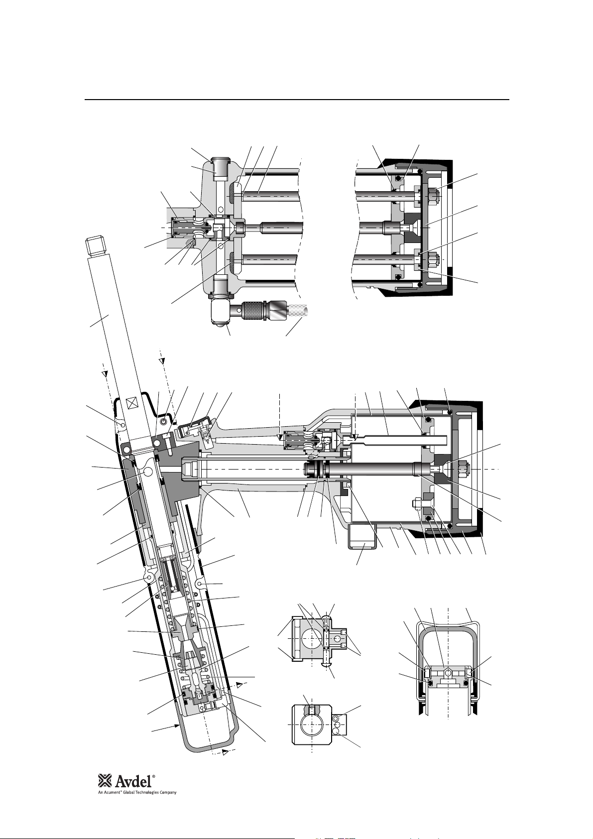
26
General Assembly of 07537-00200 Tool
29
44
2, 7
89
74
76
98
25 12
68
62
17
30
18
18
66
X
65
61
70
24
X
4
97 Ref
55
33
A
74
SECTION 'A'-'A'
32
A
69
89
87
58 Assy
78 9 77 6
14
16
56
43
13
15
38
2, 7
46
36
45
41
34
10
39
2, 7
20
57
59, 60
37
40
W
51
35
54
42
20
11
9291
71
19
96
798081
49
22
3
23
64
72
82
8
5
1
SECTION 'X'-'X'
10
2128
50
75
94
47
889395
73
48
90
67
58
PART SECTION 'W'-'W'
31
W
27

27
Parts List for 07537-00200 Tool
English
-
-
---1---------
1
1
-
21111111311111111
QTY SPARES
MOULD RETAINING NUT
MODIFIED COUNTER
BONDED SEAL
BONDED SEAL
SCREW
PLUG
PISTON
'O' RING
SEAL/WIPER
INTENSIFIER ROD
SPACER
M6x25 C'SK HEAD SCREW
CENTRE POLE MAGNET
M5 NYLOK NUT
71221-20103
71221-20105
07003-00194
07001-00442
07530-00501
71211-03201
07003-00280
07003-00274
71211-03202
07537-00501
07001-00411
07007-01993
07003-0O142
8182838485
ITEM PART Nº DESCRIPTION
-----
12111
QTY SPARES
86878889909192939495969798
-----------------------------------
11111121111111111
07002-00098
2
M5x19 C'SK SCREW
GUIDE RING
M5x6 LONG SKT HD BUTTON SCREW
WASHER
71221-20104
71210-03205
07001-00442
07002-00163
11211111112111212
TAIL JAW CYLINDER
REAR PLUG
CLIP
AIR TAIL JAW SPOOL
END CAP
TAIL JAW PISTON ASSEMBLY
LABEL (NOT SHOWN)
LABEL (NOT SHOWN)
AIR TAIL JAW CONCERTINA TUBE
SWITCH BLOCK
HEAD ASSEMBLY
HANDLE ASSEMBLY
PNEUMATIC PISTON Assembly (87 to 96)
07537 BODY MOULDING ASSEMBLY - RH
07537 BODY MOULDING ASSEMBLY - LH
TRIGGER
VALVE SEAT CLAMP NUT
TRIGGER PIN
SILENCER
RUBBER BOOT
VALVE SPOOL ASSEMBLY
TRANSFER TUBE ASSEMBLY
ON / OFF VALVE ASSEMBLY
INTENSIFIER SEAL ASSEMBLY
BODY MACHINED
JAW HOUSING
BLANKING PLUG
BLEED PLUG Assembly [Items 83 to 86]
BARREL
BARREL PLUG
07530-02207
07530-02213
07530-02220
07530-02302
07530-02603
07530-02800
07537-00201
07537-00202
07537-00203
07537-00204
07537-00300
07537-00400
07537-00500
07537-00600
07537-00700
71210-02008
71210-02009
71210-02014
71210-02024
71210-02031
71210-02055
71210-03400
07530-00208
07530-00310
07530-02201
07530-02205
07530-0O500
41
42
---
2311223222211212131221111
QTY SPARES
M4 x 5 LONG SKT HD GRUB SCREW
M4 x 10 LONG SKT HD CAP SCREW
07001-00223
07001-00401
010203040506070809101112131415161718192021222324252627282930313233343536373839
ITEM PART Nº DESCRIPTION ITEM PART Nº DESCRIPTION
07537-00200 PARTS LIST
4647484950515253545556575859606162636465666768697071727374757677787980
434445
-2---
M5 x 6 LONG SKT HD SET SCREW
M4 X 15 LONG SKT HD CAP SCREW
M4 X 6 LONG SKT HD CAP SCREW
07001-00404
07001-00445
07001-00504
-
M6 NYLOK NUT
M4 HEX NUT
M4 WASHER (PLASTIC)
'O' RING
07002-00108
07002-00134
07002-00153
07003-00027
2
2-1-1
'O' RING
'O' RING
'O' RING
'O' RING
07003-00113
07003-00121
07003-00127
07003-00167
-----------------
'O' RING
LIP SEAL (DYNAMIC)
LIP SEAL (STATIC)
'O' RING
'O' RING
'O' RING
'0' RING
'O' RING - (I/D 3.00 Sec 1.00)
1/8" STARLOCK WASHER CHROME
1/8" STARLOCK WASHER BLACK
TRIGGER VALVE
1/8" BSP PLUG
07003-00418
07003-00236
07003-00237
07003-00271
07003-00281
07003-00287
07003-00288
07003-00383
07004-00058
07004-00059
07005-00088
07005-01274
07537-00810
1112111211111
L TYPE THREADED NIPPLE
NON-RETURN VALVE
DUST CAP
07005-01972
07005-10057
07007-00017
BASE COVER MACHINED
71210-03700
71210-03800
71211-02001
71211-02002
-2-----
DIA 3 x 10 LONG SPIRAL PIN
BOOK SYMBOL LABEL (NOT SHOWN)
CE MARK LABEL (NOT SHOWN)
6" FLEXIBLE HOSE
07007-00224
07007-01503
07007-01504
07008-00010
TIE RODS
CYLINDER LINER
TOP PLATE ASSEMBLY
BASE PLATE
71211-02004
71211-02008
71213-02010
71221-02005
JAWS
SPRING
MECHANICAL CURSOR
BARREL RETURN SPRING
07151-00403
07154-00404
07271-01100
07490-03002
SEALING WASHER
COUNTER MOULDING
SPECIAL M4 SCREW
71221-02006
71221-20101
71221-20102
1
1
PISTON
STROKE LIMITER
RUBBING STRIP
07530-00203
07530-00204
07530-00206
40

28
Oil Details
Hyspin®VG 32 and AWS Oil Safety Data
Priming Pump
Priming
Priming is ALWAYS necessary after the tool has been dismantled and prior to operating. It may also be necessary to restore the full stroke
after considerable use, when the stroke may be reduced and fasteners are not fully placed by one operation of the trigger.
The recommended oil for priming is Hyspin®VG 32 available in 0.5l (part number 07992-00002) or one gallon containers (part number
07992-00006). Please find specific table and safety data below.
To enable you to follow the priming procedure opposite, you will need to obtain a priming pump 07900-00700:
First Aid
SKIN:
Wash thoroughly with soap and water as soon as possible. Casual contact requires no immediate attention. Short term contact requires no
immediate attention.
INGESTION:
Seek medical attention immediately. DO NOT induce vomiting.
EYES:
Irrigate immediately with water for several minutes. Although NOT a primary irritant, minor irritation may occur following contact.
Fire
Flash point: 232°C. Not classified as flammable.
Suitable extinguishing media: CO
2
, dry powder, foam or water fog. DO NOT use water jets.
Environment
WASTE DISPOSAL: Through authorised contractor to a licensed site. May be incinerated. Used product may be sent for reclamation.
SPILLAGE: Prevent entry into drains, sewers and water courses. Soak up with absorbent material.
Handling
Wear eye protection, impervious gloves (e.g. of PVC) and a plastic apron. Use in well ventilated area.
Storage
No special precautions.

29
Priming Procedure
Priming
IMPORTANT
DISCONNECT THE TOOL FROM THE AIR SUPPLY OR SWITCH OFF AT VALVE 70.
All operations should be carried out on a clean bench, with clean hands in a clean area.
Ensure that the new oil is perfectly clean and free from air bubbles.
Care MUST be taken at all times, to ensure that no foreign matter enters the tool, or serious damage may result.
• Remove Bleed Screw 85 and Bonded Seal 84.
• Connect air supply to tool and switch ON/OFF Valve 70 to ‘ON” position.
• Invert tool over suitable container and actuate trigger. Waste oil will be ejected through the bleed screw hole.
CARE SHALL BE TAKEN TO ENSURE THAT THE BLEED HOLE IS NOT DIRECTED TOWARDS THE OPERATOR OR OTHER
PERSONNEL.
• Disconnect air supply to tool or switch ON/OFF Valve 70 to ‘OFF” position.
• Fill the priming pump with oil.
• Screw priming pump 07900-00700 into the bleed screw hole with Bonded Seal 84 in place.
• Actuate the priming pump by pressing down and releasing several times until resistance is felt.
• Remove the priming pump.
• Replace Bleed Screw 85 and Bonded Seal 84.
• Connect air supply to tool and switch ON/OFF valve 70 to ‘ON” position.
• Check that the stroke of the tool meets the minimum specification of 30 millimetres. To check the stroke, measure the distance
between the rear of the tail jaw cylinder and body mouldings, BEFORE pressing the trigger and when the trigger is fully actuated.
The stroke is the difference between the two measurements. If it does not meet the minimum specification, repeat the priming
procedure.
Item numbers in bold refer to the general assembly drawing and parts list on pages 26-27.
English

30
Fault Diagnosis
Tool will not place Low air pressure. Increase air pressure
fastener Lack of lubrication. Lubricate tool at air inlet point
High broach load. Check fastener grip and application
hole size
Check for correct size mandrel.
Worn or broken tail jaws. New tail jaws
Tail jaws switched off. Switch on tail jaws
Air in hydraulic system. See ‘Priming Procedure’ 29
‘Mandrel Slip’ - Worn or dirty tail jaws. Clean or renew as necessary
jaws will not grip ’ Insufficient air pressure/volume. Increase air pressure/volume
mandrel ’ Tail jaw switch inoperable. Replace switch
’ Air leaks to tail jaws. Renew ‘O’ Rings 10 on Piston Assembly 51
Mandrel broken and not reaching tail jaws. Replace mandrel
Defective non-return valve. Replace non-return valve
Jaws will not Dirty tail jaws or jaw housing. Clean and lubricate
release mandrel Faulty tail jaw switch. Replace ‘O’ rings
Fasteners will not Tail jaws not switched on. Switch on tail jaws
feed through nose Worn tail jaws. Renew tail jaws
jaws Cursor orientation incorrect. Refit, ensuring correct orientation
Incorrect nose jaws. Fit correct nose jaws
Mandrel follower spring not fitted. Fit correct mandrel follower spring
Incorrect gap between fastener head Set gap to 1.5mm - 3mm (
1
/16” - 1/8”)
and nose jaws when loaded. See ‘Loading the Tool’ 10
Cursor sticking. Clean and oil cursor
Weak outer spring around cursor. Renew cursor
Incorrect mandrel follower spring fitted. Fit correct mandrel follower spring
Excessive tail jaw High broach load. Check application hole size and thickness
wear and fastener grip capability
Feeding more than Mandrel slip. Check as for ‘Mandrel Slip’, stage 2
one fastener at a Incorrect gap between fastener head Set gap to 1.5mm - 3mm (1/16” - 1/8”)
time and nose jaws when loaded See ‘Loading the Tool’ 10
Other symptoms or failures should be reported to your local Avdel authorised distributor or repair centre.
SYMPTOM POSSIBLE CAUSE REMEDY PAGE REF
Symptom Possible Cause Remedy Page Ref
 Loading...