

Avdel 74405 Instruction Manual
Hydro-Pneumatic Power Tool
74405
Instruction Manual
Original Instruction


3
Contents
Safety Instructions 4
Specifications
Tool Specification for 74405 5
Tool Specification for Intensifier 5
Tool Dimensions 5
Intent of Use 6
Putting into Service
Air Supply 7
Operating Procedure 7
Stroke Adjustment 8
Nose Assemblies
Fitting Instructions 9
Servicing Instructions 10
Nose Assembly Components 10
Servicing the Tool
Servicing 11
Daily / Weekly 11
Service Kit 11
Moly Lithium Grease EP 3753 Safety Data 12
Maintenance 13
Head Assembly 13
Air Motor Assembly 14
Handle and Trigger Assembly 14
Intensifier 15
General Assemblies and Parts Lists
Head Assembly General Assembly 16
Head Assembly Parts List 17
Intensifier General Assembly 18
Intensifier Parts List 19
Hand Tool General Assembly and Parts List 20
Priming
Oil Details 21
Hyspin®VG 32 Oil Safety Data 21
Priming Procedure 22
Fault Diagnosis
Symptom, Possible Cause and Remedy 23-24
LIMITED WARRANTY
Avdel makes the limited warranty that it’s products will be free of defects in workmanship and materials
which occur under normal operating conditions. This Limited Warranty is contingent upon: (1) the product
being installed, maintained and operated in accordance with product literature and instructions, and (2)
confirmation by Avdel of such defect, upon inspection and testing. Avdel makes the foregoing limited
warranty for a period of twelve (12) months following Avdel’s delivery of the product to the direct purchaser
from Avdel. In the event of any breach of the foregoing warranty, the sole remedy shall be to return the
defective Goods for replacement or refund for the purchase price at Avdel’s option. THE FOREGOING
EXPRESS LIMITED WARRANTY AND REMEDY ARE EXCLUSIVE AND ARE IN LIEU OF ALL OTHER WARRANTIES
AND REMEDIES. ANY IMPLIED WARRANTY AS TO QUALITY, FITNESS FOR PURPOSE, OR MERCHANTABILITY
ARE HEREBY SPECIFICALLY DISCLAIMED AND EXCLUDED BY AVDEL.
Avdel UK Limited policy is one of continuous product development and improvement and we reserve the right to change the specification of any product without prior notice.

4
Safety Rules
1 Do not use outside the design intent.
2 Do not use equipment with this tool/machine other than that recommended and supplied by Avdel UK Limited.
3 Any modification undertaken by the customer to the tool/machine, nose assemblies, accessories or any equipment supplied by Avdel
UK Limited or their representatives, shall be the customer’s entire responsibility. Avdel UK Limited will be pleased to advise upon any
proposed modification.
4 The tool/machine must be maintained in a safe working condition at all times and examined at regular intervals for damage and
function by trained competent personnel. Any dismantling procedure shall be undertaken only by personnel trained in Avdel UK
Limited procedures. Do not dismantle this tool/machine without prior reference to the maintenance instructions. Please contact Avdel
UK Limited. with your training requirements.
5 The tool/machine shall at all times be operated in accordance with relevant Health and Safety legislation. In the U.K. the “Health and
Safety at Work etc. Act 1974” applies. Any question regarding the correct operation of the tool/machine and operator safety should
be directed to Avdel UK Limited.
6 The precautions to be observed when using this tool/machine must be explained by the customer to all operators.
7 Always disconnect the airline from the tool/machine inlet before attempting to adjust, fit or remove a nose assembly.
8 Do not operate a tool/machine that is directed towards any person(s) or the operator.
9 Always adopt a firm footing or a stable position before operating the tool/machine.
10 Ensure that vent holes do not become blocked or covered.
11 The operating pressure shall not exceed 7 bar.
12 Do not operate the tool if it is not fitted with a complete nose assembly or swivel head unless specifically instructed otherwise.
13 Care shall be taken to ensure that spent stems are not allowed to create a hazard.
14 If the tool is fitted with a stem collector, it must be emptied when half full.
15 If the tool is fitted with a stem deflector, it should be rotated until the aperture is facing away from the operator and other person(s)
working in the vicinity.
16 When using the tool, the wearing of safety glasses is required both by the operator and others in the vicinity to protect against
fastener ejection, should a fastener be placed ‘in air’. We recommend wearing gloves if there are sharp edges or corners on the
application.
17 Take care to avoid entanglement of loose clothes, ties, long hair, cleaning rags etc. in the moving parts of the tool which should be
kept dry and clean for best possible grip.
18 When carrying the tool from place to place keep hands away from the trigger/lever to avoid inadvertent start up.
19 Excessive contact with hydraulic fluid oil should be avoided. To minimize the possibility of rashes, care should be taken to wash
thoroughly.
20 C.O.S.H.H. data for all hydraulic oils and lubricants is available on request from your tool supplier.
This instruction manual must be read with particular attention to the following safety rules, by any person
installing, operating, or servicing this tool.
Tool Specification for 74405
Specifications
5
Air Pressure Minimum - Maximum 5-7 bar 60 - 100 lbf/in
2
Free Air Volume Required @ 5.5 bar or 75 lbf/in
2
15 litres .525 ft
2
Stroke Maximum 16 mm .63 in
Motor Speed SPIN ON 2000 RPM
SPIN OFF 2000 RPM
Pull Force @ 5.5 bar or 75 lbf/in
2
13.84 kN 3111 lbf
Cycle Time Approximately 3 seconds
Noise Level Less than 75 dB(A)
Weight Without equipment or hose 2 kg 4.4 lb
Vibration Less than 2.5 m/s
2
Tool Specification for Intensifier
Air Pressure Minimum - Maximum 5-7 bar
Free Air Volume Required @ 5.5 bar or 75 lbf/in
2
3.6 litres
Noise Level Less Than 75 dB(A)
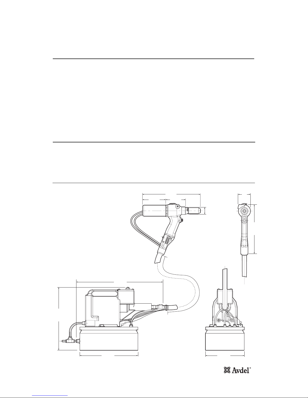
300
445
326
250
35
200
120
102
300 66
Tool Dimensions
Dimensions in millimetres

6
Intent of Use
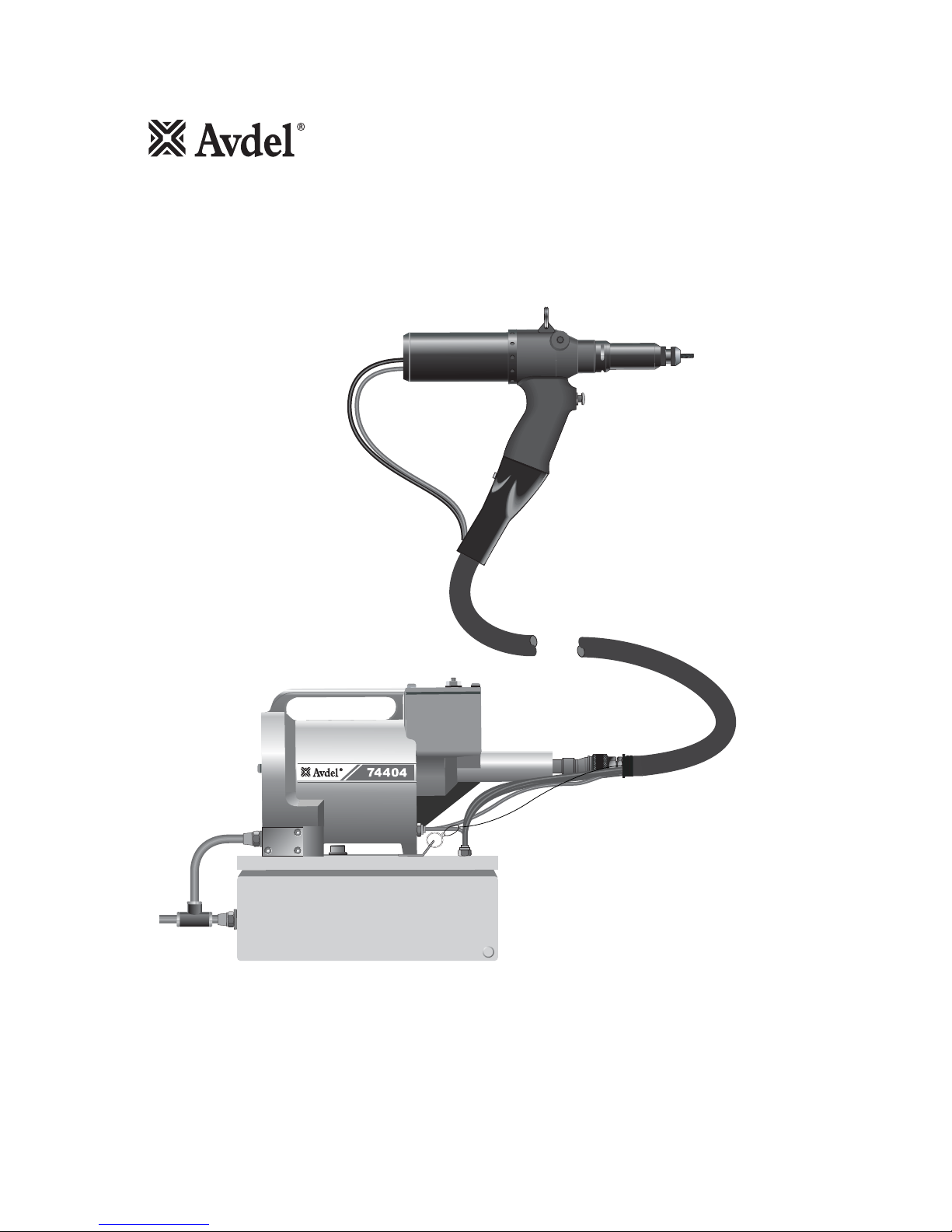
The hydro-pneumatic 74405 tool is designed to place Avdel® Threaded Inserts at high speed making it ideal for batch or flow-line
assembly in a wide variety of applications throughout all industries.
A complete tool is made up of two seperate elements which will be supplied individually:
• Base Tool - 74405-01000
• Nose Assembly - see datasheet 07900-00857

Air Supply
Putting into Service
7
All tools are operated with compressed air at an optimum pressure of 5.5 bar. We recommend the use of pressure regulators and
filtering systems on the main air supply. These should be fitted within 3 metres of the tool (see diagram below) to ensure
maximum tool life and minimum tool maintenance.
Air supply hoses should have a minimum effective working pressure rating of 150% of the maximum pressure produced in the system
or 10 bar, whichever is the highest. Air hoses should be oil resistant, have an abrasion resistant exterior and should be armoured where
operating conditions may result in hoses being damaged. All air hoses MUST have a minimum bore diameter of 6.4 millimetres or
1
/
4
inch.
Read servicing daily details page 11.
Follow the steps below when connecting the tool to the intensifier and main air supply:
• Push the end of the large hydraulic hose from the tool into the quick release connector on the end of the intensifier.
• On the front face of the intensifier (Refer to page 18):
• Push the black pneumatic (4mm OD) line into the reducer fitting which is located in the left hand bulkhead connector.
• Push the blue pneumatic (4mm OD) line into the plastic collet of the right hand bulkhead connector.
• On the top face of the control box (Refer to page 20):
• Push the blue pneumatic (6mm OD) line into the reducer labelled ‘Air Motor Spin On’ on the top face of the control box - LH side.
• Push the black pneumatic (6mm OD) line into the reducer labelled ‘Air Motor Spin Off’ on the top face of the control box - middle.
• Push the black pneumatic (4mm OD) line from the flexible hose assembly into the reducer labelled ‘Aux Spin Off’ on the top face
of the control box - RH side.
• Push the black pneumatic (4mm OD) line from the reducer fitting on the intensifier into the reducer labelled ‘Intensifier Timer’ on
the top face of the control box.
• Fit a pneumatic hose between the male connector at the rear of the intensifier and main air supply.
8
6
4
2
0
1
0
1
2
14
1
6
TAKE OFF POINT
FROM
MAIN SUPPLY
STOP COCK
(USED DURING MAINTENANCE
OF FILTER/REGULATOR OR LUBRICATION UNITS)
MAIN SUPPLY
DRAIN POINT
AIR LUBRICATION
PRESSURE REGULATOR
AND FILTER (DRAIN DAILY)
3 METRES MAXIMUM
Operating Procedure
• Before you use the tool, remove the Screw 3* on top of the oil reservoir of the intensifier to allow venting. Replace screw when
transporting the intensifier.
• Ensure that a nose assembly suitable for the fastener is fitted (see separate nose assembly data sheet 07900-00857).
• Connect the tool to the intensifier and the intensifier to the air supply.
• Offer up insert, lip first to the drive screw. A light pressure will start the motor and automatically thread the insert up against the
nose and stop.
• Insert the fastener into the application squarely.
• Fully depress the trigger. This will both place the insert into the application and reverse it off the drive screw.
* Item number refers to Intensifier general assembly and parts list on pages 18 and 19.
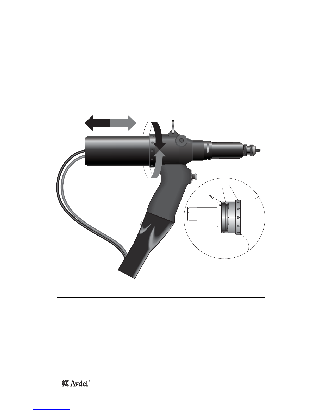
Stroke Adjustment
Putting into Service
8
This adjustment is necessary to insure optimum insert deformation. It is suggested, therefore, that a test plate with the same thickness
and hole size as the workpiece is used.
If deformation is insufficient, the insert willl rotate inside the application.
If deformation is excessive, thread distortion will occur and possibly drive screw fracture.
The stroke is adjusted by the amount the Stroke Adjustment Lock Nut 12, (parts list page 17), is screwed in or out. To shorten the
stroke, screw in; to lengthen the stroke, unscrew the rear casing. Adjust until optimum deformation is obtained.
Item numbers in bold refer to the illustrations on pages 16 and 17.
IMPORTANT
At the correct stroke the rear faces of the Adjustment Ring 47 and the Stroke Adjustment Lock Nut 12 will be
flush.
The Adjustment Ring 47 must not be wound out beyond this point.
Note
47
12
Rear Casing (48)
Removed
Faces Flush
See
Note
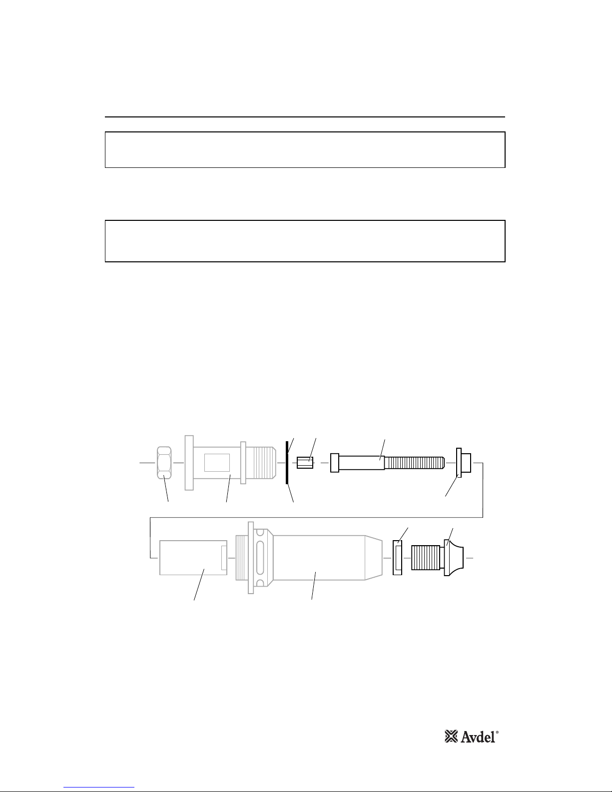
Fitting Instructions
IMPORTANT
The Nose Assembly must be fitted before operating the tool.
It is essential that the correct nose assembly is fitted prior to operating the tool. By knowing your original complete tool part number
or the details of the fastener to be placed, you will be able to order a new complete nose assembly using the datasheet 0790000857 for nose assembly components.
* Item included in the 74405 Service Kit. For complete list see page 11.
9
IMPORTANT
The air supply must be disconnected when fitting or removing nose assemblies unless specifically instructed
otherwise.
• If still fitted remove the nose casing and adaptor nut.
• Insert Drive Shaft 4 into spindle.
• Fit Drive Screw 3 onto Drive Shaft 4.
• Insert Reducing Sleeve 5 (if required) into the adaptor nut.
• Position Friction Ring 51* onto the spindle.
• Screw the adaptor nut onto the spindle.
• Hold the spindle with a spanner*, tighten the lock nut anti-clockwise, ensuring the friction ring is not caught between the faces of the
spindle and the adapter nut.
• Screw on the nose casing together with Nose Tip 1 and nose tip Lock Nut 2.
• The reverse operation is carried out for equipment removal.
• With tool still disconnected from air supply, screw one insert onto the drive screw manually making sure the insert is flush with the end of
the drive screw.
• Set nose tip in exact position and lock nose tip nut clockwise with a spanner*.
• Remove the insert from the drive screw.
(Item numbers in bold refer to illustration below, 51* refers to illustration on page 16).
1
2
3
5
SPINDLE FRICTION RING
LOCK NUT
ADAPTOR NUT
NOSE CASING
4
51
*
*
Items in grey are included in the base tool.
 Loading...