

Avdel 74201 Instruction Manual

Threaded Insert Power Tool
74201
Instruction Manual
Original Instruction


3
Contents
LIMITED WARRANTY
Avdel makes the limited warranty that its products will be free of defects in workmanship and materials
which occur under normal operating conditions. This Limited Warranty is contingent upon: (1) the product
being installed, maintained and operated in accordance with product literature and instructions, and (2)
confirmation by Avdel of such defect, upon inspection and testing. Avdel makes the foregoing limited
warranty for a period of twelve (12) months following Avdel’s delivery of the product to the direct purchaser
from Avdel. In the event of any breach of the foregoing warranty, the sole remedy shall be to return the
defective Goods for replacement or refund for the purchase price at Avdel’s option. THE FOREGOING
EXPRESS LIMITED WARRANTY AND REMEDY ARE EXCLUSIVE AND ARE IN LIEU OF ALL OTHER WARRANTIES
AND REMEDIES. ANY IMPLIED WARRANTY AS TO QUALITY, FITNESS FOR PURPOSE, OR MERCHANTABILITY
ARE HEREBY SPECIFICALLY DISCLAIMED AND EXCLUDED BY AVDEL.
Avdel UK Limited policy is one of continuous product development and improvement and we reserve the right to change the specification of any product without prior notice.
Safety Rules 4
Specifications
Tool Specification 5
Tool Dimensions 5
Intent of Use 6
Putting into Service
Air Supply 7
Force Adjustment 7
Operating Procedure 7
Nose Assemblies
Fitting Instructions 8
Servicing Instructions 8
Selection 9
Servicing the Tool
Daily / Weekly 10
Molykote®55m Lithium Grease Safety Data 10
Service Kit 11
Maintenance
Tool Servicing 12
Pneumatic Cylinder 12
Rod Guide 12
Trigger 12
Swivel Air Inlet 12
Differential Valve 13
Head Assembly 13
Rear Casing 13
Distributor 13
Hydraulic Piston and Air Motor Assembly 13
General Assembly of Base Tool
General Assembly of Base Tool 74201 - 12000 14
Parts List for 74201 - 12000 15
Pressure Switch Assembly 16
Pressure Switch Removal 16
Priming
Oil Details 17
Hyspin®VG 32 Oil Safety Data 17
Priming Procedure 17
Fault Diagnosis
Symptom, Possible Cause and Remedy 18-19

4
Safety Rules
1 Do not use outside the design intent.
2 Do not use equipment with this tool/machine other than that recommended and supplied by Avdel UK Limited.
3 Any modification undertaken by the customer to the tool/machine, nose assemblies, accessories or any equipment supplied by
Avdel UK Limited or their representatives, shall be the customer’s entire responsibility. Avdel UK Limited will be pleased to advise
upon any proposed modification.
4 The tool/machine must be maintained in a safe working condition at all times and examined at regular intervals for damage and
function by trained competent personnel. Any dismantling procedure shall be undertaken only by personnel trained in Avdel UK
Limited procedures. Do not dismantle this tool/machine without prior reference to the maintenance instructions. Please contact
Avdel UK Limited with your training requirements.
5 The tool/machine shall at all times be operated in accordance with relevant Health and Safety legislation. In the U.K. the “Health
and Safety at Work etc. Act 1974” applies. Any question regarding the correct operation of the tool/machine and operator safety
should be directed to Avdel UK Limited.
6 The precautions to be observed when using this tool/machine must be explained by the customer to all operators.
7 Always disconnect the air line from the tool/machine inlet before attempting to adjust, fit or remove a nose assembly.
8 Do not operate a tool/machine that is directed towards any person(s) or the operator.
9 Always adopt a firm footing or a stable position before operating the tool/machine.
10 Ensure that vent holes do not become blocked or covered.
11 The operating pressure shall not exceed 7 bar.
12 Do not operate the tool if it is not fitted with a complete nose assembly or swivel head unless specifically instructed otherwise.
13 Care shall be taken to ensure that spent stems are not allowed to create a hazard.
14 If the tool is fitted with a stem collector, it must be emptied when half full.
15 If the tool is fitted with a stem deflector, it should be rotated until the aperture is facing away from the operator and other
person(s) working in the vicinity.
16 When using the tool, the wearing of safety glasses is required both by the operator and others in the vicinity to protect against
fastener ejection, should a fastener be placed ‘in air’. We recommend wearing gloves if there are sharp edges or corners on the
application.
17 Take care to avoid entanglement of loose clothes, ties, long hair, cleaning rags etc. in the moving parts of the tool which should
be kept dry and clean for best possible grip.
18 When carrying the tool from place to place keep hands away from the trigger/lever to avoid inadvertent start up.
19 Excessive contact with hydraulic fluid oil should be avoided. To minimize the possibility of rashes, care should be taken to wash
thoroughly.
20 C.O.S.H.H. data for all hydraulic oils and lubricants is available on request from your tool supplier.
This instruction manual must be read with particular attention to the following safety rules, by any person
installing, operating, or servicing this tool.
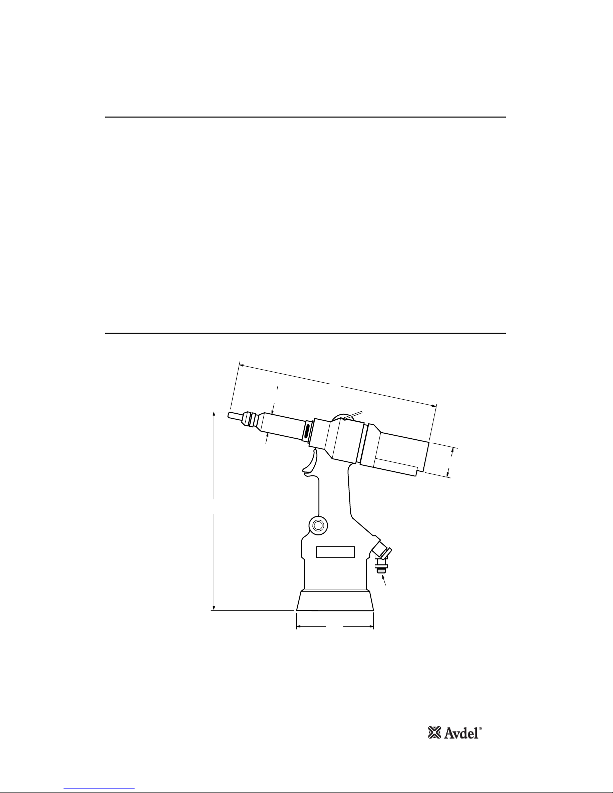
Tool Specification
Tool Dimensions
Specifications
5
Air Pressure Minimum - Maximum 5-7 bar (75-100 lbf/in2)
Free Air Volume Required @ 5 bar/75 lbf/in
2
7.5 litres (0.26 ft3)
Stroke Maximum 7 mm (0.276 in)
Motor Speed Spin On 2000 rpm
Spin Off 2000 rpm
Pull Force @ 5 bar/75 lbf/in
2
17.65 kN (3967.20 lbf)
Cycle Time Approximately 2.5 seconds
Noise Level Less than 75 dB(A)
Weight Without nose equipment 2.1 kg (4.63 lb)
Vibration Less than 2.5 m/s2(8 ft/s2)
Placing Features Inserts M3 - M8
100Ø
3.94Ø
1/4 GAS
295
11.61
11.81
300
45
Ø
1.77Ø
25Ø
0.98Ø
Dimensions shown in bold are millimetres. Other dimensions are in inches.

6
Intent of Use
The 74201 hydro-pneumatic tool is designed for placing Avdel®threaded inserts and is ideal for batch or flow-line assembly in a wide
variety of applications throughout all industries.
The tool works on the principle of adjustment of the force rather than the stroke. The advantage lies in the fact that it is possible to
place the same insert (of the specified tightening thickness) in materials of different thicknesses, after setting the tool for the greatest
thickness.
The tool is available in the basic configuration using code 74201-12000. In addition there are nose assembly kits available to match
the type and size of the insert which is to be placed. (see selection tables on page 9). The tables also give the complete tool code
(basic tool plus nose assembly kits).
Nose assemblies must be fitted as described on page 8.
• Connect the tool to the air supply. Adjust the pull force.
• Offer up insert, lip first, to the drive screw. A slight pressure on the trigger will start the motor and automatically thread the insert
up against the nose tip and stop.
• Insert fastener squarely into application.
• Fully depress the trigger. This will both place the insert into the application and disengage it from the drive screw.
Do not connect the tool to the air supply until all the components are in place, as indicated in the drawing on page 14.
Item numbers in bold refer to the General Assembly drawing and Parts List (pages 14-15).
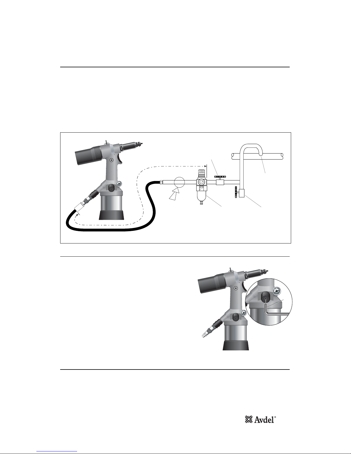
Air Supply
Force Adjustment
Operating Procedure
Putting into Service
7
All tools are operated with compressed air at an optimum pressure of 5.5 bar. We recommend the use of pressure regulators and
automatic cooling/filtering systems on the main air supply. These should be mounted within 3 metres of the tool (see diagram below) to
ensure maximum tool life with minimum tool maintenance.
The flexible hoses should have a minimum effective working pressure rating of 150% of the maximum pressure produced in the system
or 10 bar, whichever is the highest. Air hoses should be oil resistant, have an abrasion resistant exterior and should be armoured
where operating conditions may result in hoses being damaged. All air hoses MUST have a minimum bore diameter of 6.4 millimetres
or
1
/4 inch.
Read servicing daily details page 10.
8
6
4
2
0
1
0
1
2
14
1
6
TAKE OFF POINT
FROM MAIN SUPPLY
STOP COCK
(USED DURING MAINTENANCE
OF FILTER/REGULATOR
OR LUBRICATION UNITS)
MAIN SUPPLY
DRAIN POINT
PRESSURE REGULATOR
AND FILTER
(DRAIN DAILY)
3
M
E
T
R
E
S
M
A
X
I
M
U
M
AIR LUBRICATION
PERMISSABLE
Allen
Key
After fitting the appropriate nose assembly for the insert to be placed,
connect the tool to the air supply hose.
Using the 3mm allen key, unscrew the Regulator 93* a few turns until
pressing the Trigger 40produces no pull on the spindle.
To confirm this, screw an insert onto the spindle and press the trigger. The
insert will not deform and the tool will begin to spin off.
To adjust the pull force, screw in the Regulator 93*approximately half a turn
and repeat the operation with the same insert (for each trial operation, screw
in the Regulator 93* until deformation of the insert takes place without any
change in thickness). When this stage is reached, this will be the minimum
force required to deform the insert .
After a successful trial insert deformation, check the thickness and increase
the force if the insert is not sufficiently formed.
Usually, this last adjustment requires a slight increase in the tightening of
Regulator 93*.
The tool is now ready to operate.
When dealing with different thicknesses, set it for the greatest thickness.
93* See page 16 Pressure Switch Assembly.

8
Fitting Instructions
Servicing Instructions
Nose Assemblies
It is essential that the correct nose assembly is fitted prior to operating the tool. If you know the code for your complete, original tool,
or the details of the fastening systems which are to be used, you will be able to order a new complete nose assembly using the
selection tables on page 9.
IMPORTANT
The air supply must be disconnected when fitting or removing nose assemblies
unless specifically instructed otherwise.
IMPORTANT
Do not press against the drive screw when tool is connected to the air supply with no
insert in as the drive screw will start to run axially.
Nose assemblies should be serviced at weekly intervals (see page 10).
• Remove the complete nose assembly using the reverse procedure to the ‘Fitting Instructions’.
• Any worn or damaged parts should be replaced with new parts.
• Particularly check wear on the Drive Screw 3.
• Assemble according to fitting instructions (see above).
* Refers to items included in the 74200 Service Kit. For complete list see page 11.
Item numbers in bold refer to illustration below:
• If still fitted, remove the nose casing and the adaptor nut.
• Insert Drive Shaft 4 into spindle.
• Fit Drive Screw 3 onto Drive Shaft 4.
• Insert Reducing Sleeve 5 (if specified) into the adaptor nut.
• Screw the adaptor nut onto the spindle.
• Hold the spindle with a spanner* and tighten the adaptor nut clockwise.
• While holding the adaptor nut with the spanner*, tighten the lock nut anti-clockwise.
• Screw on the nose casing and Nose Tip 1 with the nose tip Lock Nut 2.
• The reverse operation is carried out for equipment removal.
1
2
3
5
SPINDLE
LOCK NUT
ADAPTOR NUT
NOSE CASING
4
Items in grey are included in the base tool.
Items in black make up the nose assembly.
• With the tool still disconnected from the air supply, screw an insert onto the drive screw manually. Position Nose Tip 1 on the nose
casing and lock it with Lock Nut 2 so that the insert lines up with the end of Drive Screw 3.
• Lock the nose tip lock nut by turning clockwise with a spanner*.
• Remove the insert from drive screw.
 Loading...