

Avdel 74100 Instruction Manual
Instruction Manual
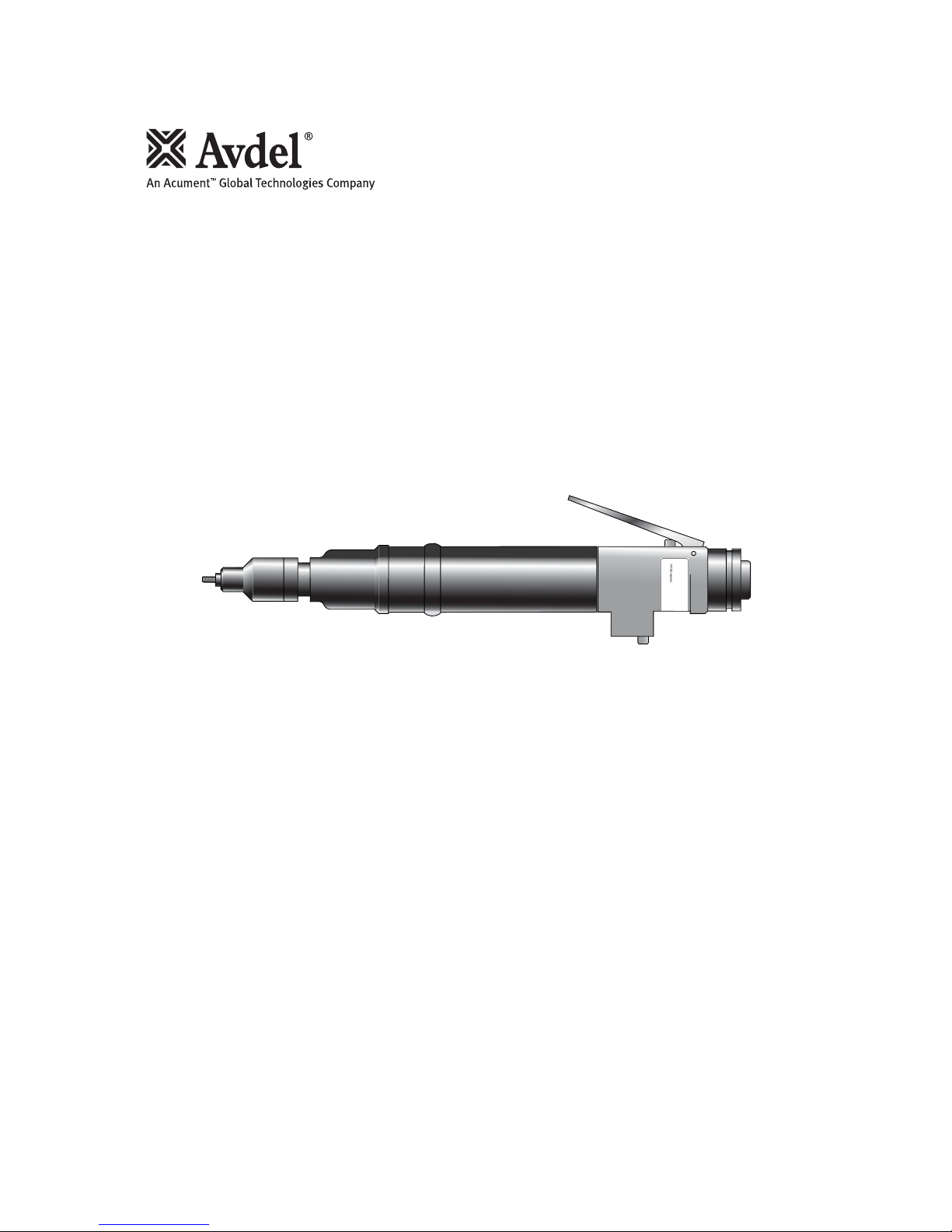
Threaded Insert Power Tool
74100


3
Contents
Safety Rules 4
Tool Specifications 5
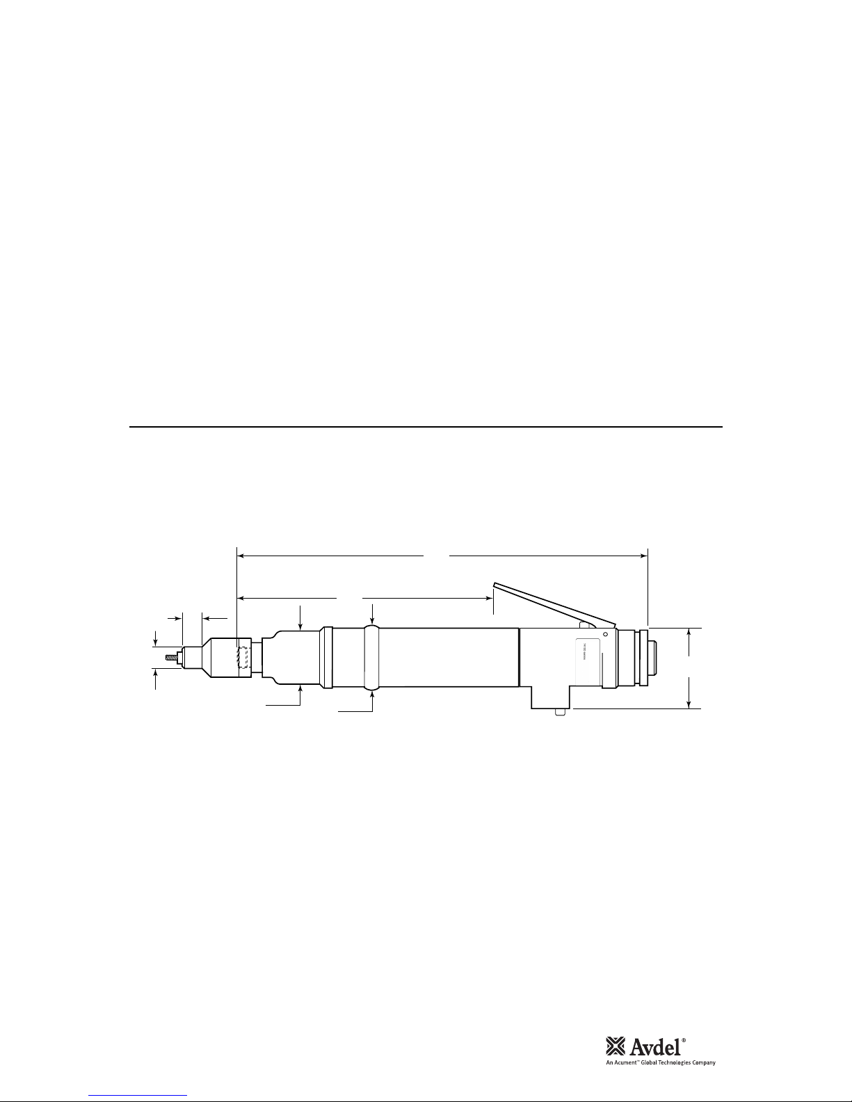
Tool Dimensions 5
Intent of Use
Tool Selection 6
Putting into Service
Air supply 7
Operating Procedure 7
Clutch Adjustment 8
Accessories 8
Nose Assemblies
Fitting Instructions 9
Servicing Instructions 9
Nose Assembly Components 10
Servicing the Tool
Daily Servicing 11
Weekly Servicing 11
Safety Data (Grease) 12
Maintenance
Control Valve Assembly 13
Clutch Assembly 14 & 15
Motor Assembly 16
Gearbox Assembly 17
Setting the Push Rod 18
General Assembly of Base Tool 20
Parts List 21
Troubleshooting 22 & 23
Avdel UK Limited policy is one of continuous product development and improvement and we reserve the right to change the specification of any product without prior notice.
Warranty
Avdel installation tools carry a 12 month warranty against defects caused by faulty materials or
workmanship, the warranty period commencing from the date of delivery confirmed by invoice or delivery
note.
The warranty applies to the user/purchaser when sold through an authorised outlet, and only when used for
the intended purpose. The warranty is invalidated if the installation tool is not serviced, maintained and
operated according to the instructions contained in the Instruction and Service Manuals.
In the event of a defect or failure, and at its sole discretion, Avdel undertakes only to repair or replace faulty
components.

4
Safety Rules
1 Do not use outside the design intent.
2 Do not use equipment with this tool other than that recommended and supplied by Avdel UK Limited.
3 Any modification undertaken by the customer to the tool/machine, nose assemblies, accessories or any equipment
supplied by Avdel UK Limited or their representatives, shall be the customer’s entire responsibility. Avdel UK Limited
will be pleased to advise upon any proposed modification.
4 The tool/machine must be maintained in a safe working condition at all times and examined at regular intervals for
damage and function by trained competent personnel. Any dismantling procedure shall be undertaken only by
personnel trained in Avdel UK Limited procedures. Do not dismantle this tool/machine without prior reference to the
maintenance instructions. Please contact Avdel UK Limited with your training requirements.
5 The tool/machine shall at all times be operated in accordance with relevant Health and Safety legislation. In the U.K.
the “Health and Safety at Work etc. act 1974” applies. Any question regarding the correct operation of the
tool/machine and operator safety should be directed to Avdel UK Limited.
6 The precautions to be observed when using this tool/machine must be explained by the customer to all operators.
7 Always disconnect the airline from the tool/machine inlet before attempting to adjust, fit or remove a nose
assembly.
8 Do not operate a tool/machine that is directed towards any person(s).
9 Ensure that vent holes do not become blocked or covered and that hoses are always in good condition.
10 The operating pressure shall not exceed 6.3 bar - 94.5 lbf/in
2
.
11 Do not operate the tool without full nose equipment in place.
12 When using the tool, the wearing of safety glasses is required both by the operator and others in the vicinity to
protect against fastener projection, should a fastener be placed ‘in air’. We recommend wearing gloves if there are
sharp edges or corners on the application.
13 Take care to avoid entanglement of loose clothes, ties, long hair, cleaning rags etc. in the moving parts of the tool
which should be kept dry and clean for best possible grip.
14 When carrying the tool from place to place keep hands away from the trigger/lever to avoid inadvertent start up.
15 Always adopt a firm footing or a stable position before operating the tool and be aware of a torque reaction on the
hands when the tool is operating, particularly during the reversing sequence. Grip the tool firmly to be able to
counter the torque reaction, but not too tightly.
16 Keep hands away from the rotating drive screw and the nose end of the tool. If a fastener becomes jammed on the
drive screw, shut off the air supply and drain the supply line to the tool before attempting to dislodge it.
17 The tool is not electrically insulated.
18 This tool is not designed for use in combustible or explosive atmospheres.
This instruction manual must be read with particular attention to the following safety rules, by any
person installing, operating, or servicing this tool.
5
Tool Specification
Tool Dimensions
Specifications
Air Pressure Minimum - Maximum 4-6.3 bar (60-94.5 lbf/in2)
Free Air Volume Required @ 6.3 bar / 94 lbf/in
2
7.5 litres/sec
Motor Speed @ 75 lb/in2minimum 1100 rpm (clockwise)
Cycle time Approx 3 seconds
Noise Level 75 dB(A)
Weight Without nose equipment 1.076 kg (2.37 lb)
Vibration Less than 2.5 m/s2(8 ft/s2 )
35.6
1.401
40
1.575
A
B
49
1.929
180
7.086
273
10.75
Dimensions shown in bold are millimetres. Other dimensions are in inches

6
Intent of Use
Tool Selection
The pneumatic 74100 type tool is designed to place Avdel®threaded inserts at high speed making it ideal for batch or
flow-line assembly in a wide variety of applications throughout all industries.
Use the selection table below to select a complete tool which will be fitted with the correct nose assembly for the
threaded insert selected. ‘A’ and ‘B’ dimensions will help you assess the accessibility of your application.
It is also possible to order the base tool only (part number 74100-12000). For details of Nose Assemblies see page 10.
4 UNC 7 - 9 84100-15020 13 111/27/16 07556-09954 74100-01054
6 UNC 16 - 18 84100-15010 13 111/27/16 07556-09956 74100-01056
8 UNC 16 - 18 84100-15010 13 121/215/32 07556-09958 74100-01058
4 UNF 7 - 9 84100-15020 13 111/27/16 07556-09974 74100-01074
6 UNF 16 - 18 84100-15010 13 111/27/16 07556-09976 74100-01076
8 UNF 16 - 18 84100-15010 13 121/215/32 07556-09978 74100-01078
6 BA 7 - 9 84100-15020 13 111/27/16 07556-09936 74100-01036
4 BA 16 - 18 84100-15010 13 111/27/16 07556-09934 74100-01034
M3 7 - 9 84100-15020 13 111/27/16 07556-09983 74100-01083
M4 16 - 18 84100-15010 13 111/27/16 07556-09984 74100-01084
8 UNC 16 - 18 84100-15010 13 101/213/32 07552-09558 74100-02058
8 UNF 16 - 18 84100-15010 13 101/213/32 07552-09578 74100-02078
M3 16 - 18 84100-15010 13 191/23/4 07552-09583 74100-02083
M4 16 - 18 84100-15010 13 171/221/32 07552-09584 74100-02084
M4 16 - 18 84100-15010 13 151/219/32 07556-09184 74100-04084
3
/16 BSW 20 - 25 84100-15000 13 121/215/32 07556-09816 74100-00016
4 UNC 5 - 7 84100-15020 13 121/215/32 07556-09854 74100-00054
6 UNC 9 - 11 84100-15010 13 121/215/32 07556-09856 74100-00056
8 UNC 13 - 15 84100-15010 13 101/213/32 07556-09858 74100-00058
10 UNC 20 - 25 84100-15000 13 121/215/32 07556-09850 74100-00050
6 UNF 9 - 11 84100-15010 13 121/215/32 07556-09876 74100-00076
8 UNF 13 - 15 84100-15010 13 101/213/32 07556-09878 74100-00078
10 UNF 20 - 25 84100-15000 13 121/215/32 07556-09870 74100-00070
6 BA 5 - 7 84100-15020 13 121/215/32 07556-09836 74100-00036
4 BA 9 - 11 84100-15010 13 121/215/32 07556-09834 74100-00034
2 BA 20 - 25 84100-15000 13 121/215/32 07556-09832 74100-00032
M3 5 - 7 84100-15020 13 121/215/32 07556-09883 74100-00083
M4 13 - 15 84100-15010 13 101/213/32 07556-09884 74100-00084
M5 20 - 25 84100-15000 13 121/215/32 07556-09885 74100-00085
M4 16 - 18 84100-15010 13 151/219/32 07556-09184 74100-04084
M4 16 - 18 84100-15010 13 181/223/32 07556-09284 74100-06084
74100 TOOL SELECTION
NOSE (see drawing opposite for A & B)
TORQUE
SETTING (lbf ins)
Ø
COMPLETE
TOOL PART Nº
NOSE ASSY PART N º
A (mm)
INSERT
NAME & SERIES
B (mm) A (in) B (in)
UNSET
CLUTCH PART Nº
THIN SHEET
NUTSERT
®
(9650)
SUPERSERT
®
(FB00)
LG. FLANGE
HEXSERT® (9498)
STANDARD
NUTSERT
®
(9500)
(9538)
L/F THIN SHEET
NUTSERT® (9698)
HEXSERT
®
(9688)
7
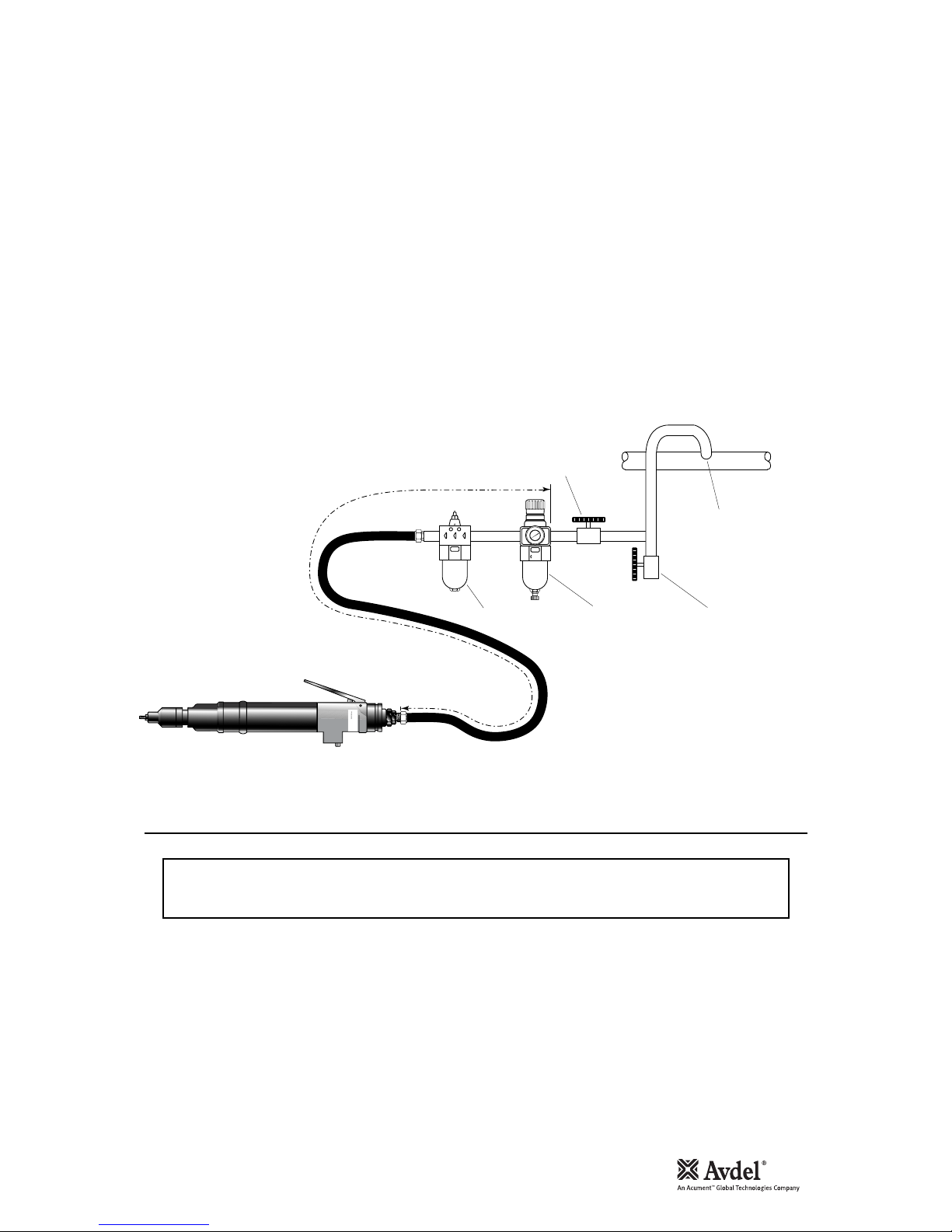
Air Supply
Operating Procedure
Putting into Service
All tools are operated with compressed air at an optimum pressure of 5.5 bar. We recommend the use of pressure regulators and
automatic oiling/filtering systems on the main air supply. These should be fitted within 3 metres of the tool (see diagram below) to
ensure maximum tool life and minimum tool maintenance.
Air supply hoses should have a minimum working effective pressure rating of 150% of the maximum pressure produced in the system
or 10 bar, whichever is the highest. Air hoses should be oil resistant, have an abrasion resistant exterior and should be armoured
where operating conditions may result in hoses being damaged. All air hoses MUST have a minimum bore diameter of 6.4 millimetres
or 1/4 inch.
Read servicing daily details page 11.
8
6
4
2
0
10
12
14
16
TAKE OFF POINT
FROM MAIN SUPPLY
STOP COCK
(USED DURING MAINTENANCE
OF FILTER/REGULATOR
OR LUBRICATION UNITS)
MAIN SUPPLY
DRAIN POINT
PRESSURE REGULATOR
AND FILTER
(DRAIN DAILY)
LUBRICATOR
3
M
E
T
R
E
S
IMPORTANT
When placing Standard Nutserts, lubricate the drive screw of the tool every 25 placings. This is best
achieved by wiping the drive screw with a sponge soaked with STP Lubricant part number 07992-00013.
OPTION 1
• Ensure that the correct nose equipment is fitted.
• Connect the tool to the air supply.
• Place the insert into the prepared hole of the application.
• Locate the drive screw of the tool into the insert.
• Operate the lever. The drive screw will screw into and
collapse the insert, then automatically reverse out.
OPTION 2
• Ensure that the correct nose equipment is fitted.
• Connect the tool to the air supply.
• Screw the insert lip first onto the drive screw of the tool.
• With the insert on the tool, locate it into the prepared
hole of the application.
• Operate the lever. The drive screw will screw into and
collapse the insert, then automatically reverse out.
8
Clutch Adjustment
Accessories
Putting into Service
If you have ordered a complete tool the clutch will be set for the specified insert.
When purchased as a spare part, the clutch is supplied unset.
Correct clutch setting is necessary to ensure optimum deformation of the insert. If the deformation is insufficient (clutch
torque too low) the insert will rotate in the application. If the deformation is excessive (clutch torque too high) thread distortion
will occur and extensive wear on the drivescrew, may lead to fracture.
For details on how to adjust the clutch refer to maintenance instructions referring to the clutch on page 15.
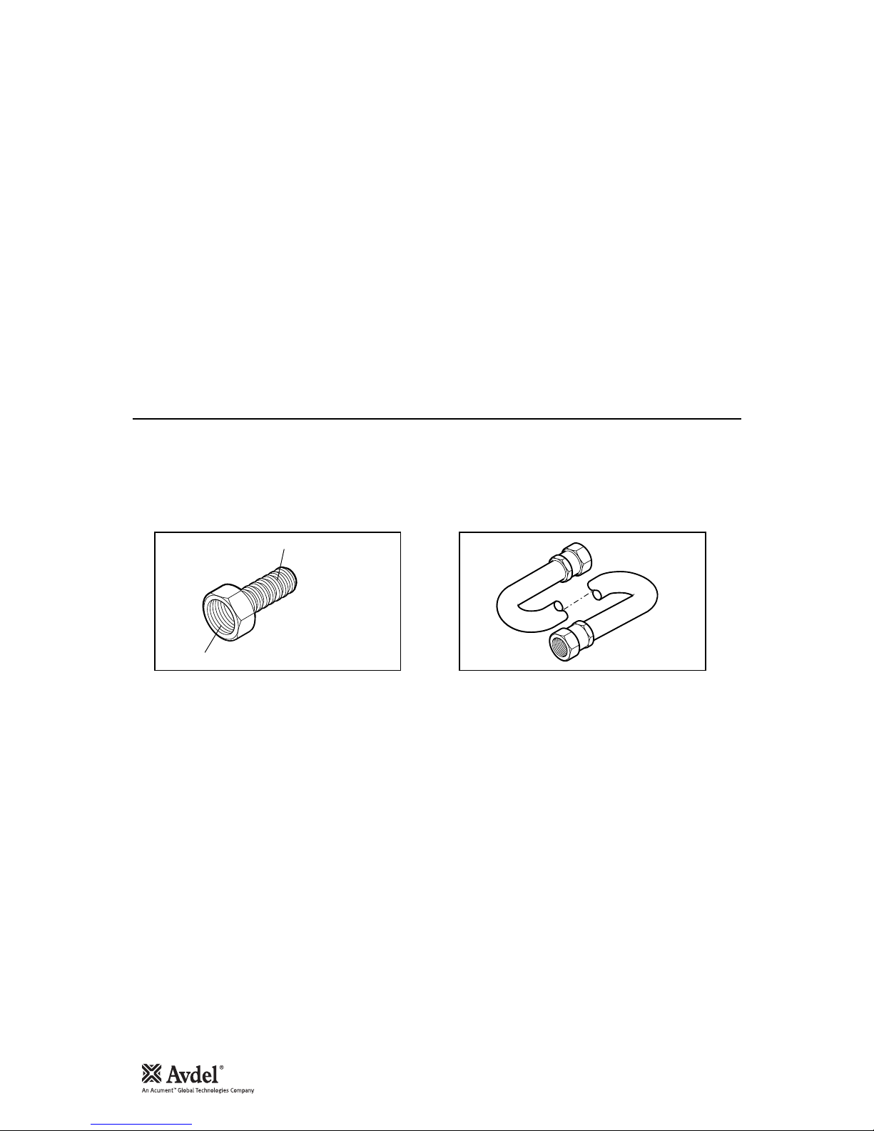
Two different accessories are available to make the connection to your air supply:
Hose Connector
part nº 07005-00276
Hose Assembly
part nº 07008-000324
TO FIT 6.4 mm (1/4") BORE PIPE
1/4" BSP
L = 137 cm

9
Fitting Instructions
Servicing Instructions
Nose Assemblies
Nose assemblies are specifically designed for each size and type of insert. If you have purchased a complete tool, it will already be
fitted with the correct nose assembly for your insert.
It is essential that the correct nose assembly is fitted prior to operating the tool. By knowing your original complete tool part number
or the details of the insert to be placed, you will be able to order a new complete nose assembly using the selection table page 10.
IMPORTANT
The air supply must be disconnected when fitting or removing nose assemblies unless specifically instructed
otherwise.
Before fitting the nose equipment, ensure the clutch on the tool is set to the correct torque for the insert being placed. (Torque values
are on page 6.)
• Where applicable, insert sleeve 8 and thrust spring 9 into nose housing 2.
• Coat thrust washers 3 and thrust bearing 4 with high pressure grease (eg. Shell Alvania E.P.I.) and locate them in the order shown
below into the nose housing 2.
• Where applicable, fit spacer 5 through thrust washers and thrust bearings.
• Insert drive screw 1 through the above assembly.
• Fit drive shaft 6 into the hexagon hole in the drive screw head.
• Insert stop 11 and spring 10 into the front of the base tool.
• Screw adaptor 7 into clutch housing of the base tool (left hand thread).
• Offer up the nose assembly to the adaptor. It will be necessary to rotate the drive screw by hand to line up the hexagon on the
drive shaft 6 with the hexagonal hole in the front jaw of the base tool.
• Screw the nose housing 2 onto the adaptor 7 and tighten with a spanner (left hand thread).
2
8
9
1
6
10
34 3
5
11
7
Nose assemblies should be serviced at weekly intervals.
• Remove the complete nose assembly using the reverse procedure to the ‘Fitting Instructions’.
• Any worn or damaged part should be replaced.
• Particularly check wear on drivescrew, thrust washers and thrust bearing.
• Lubricate thrust washers and thrust bearings with high pressure grease (eg Shell Alvania E.P.I.)
• Check springs are not distorted.
• Assemble according to fitting instructions.
 Loading...