

Avdel 73435-02000 Instruction Manual
a
Avder
Instruction Manual
Original Instruction
Alrm50 Installation Tool 73435-02000
Hydro-Electric Power Tool
Instruction Manual
Original Instruction
AV™50 Installation Tool – 73435-02000
Hydro-Electric Power Tool

Contents
Safety Instructions
3
to
4
Specification
5
Intent of Use
5
Placing Tool Specification
5
Placing Tool Dimensions
6
Putting Into Service
7
Principle of Operation
7
Preparation for Use
8
Operating Instructions
9
Servicing the Tool
10
Daily / Weekly / Annually
10
Service Kit
10
Dismantling Instructions
11 to 15
General Assembly of Installation Tool 73435-02000
16
General Assembly Drawing
16 to 17
Parts List
178
Safety Data
19
Enerpac® HF Hydraulic Oil - Safety Data
19
MolyLithium Grease EP 3753 - Safety Data
19
Molykote
®
111 Grease - Safety Data
20
Fault Diagnosis
21
Symptom / Possible Cause / Remedy
21 to 22
Declaration of Conformity
24
LIMITED WARRANTY
Avdel makes the limited warranty that its products will be free of defects in workmanship and materials which
occur under normal operating conditions. This Limited Warranty is contingent upon: (1) the product being
installed, maintained and operated in accordance with product literature and instructions, and (2) confirmation by
Avdel of such defect, upon inspection and testing. Avdel makes the foregoing limited warranty for a period of one
hundred and eighty (180) days following Avdel's delivery of the product to the direct purchaser from Avdel. In the
event of any breach of the foregoing warranty, the sole remedy shall be to return the defective Goods for
replacement or refund for the purchase price at Avdel's option. THE FOREGOING EXPRESS LIMITED WARRANTY
AND REMEDY ARE EXCLUSIVE AND ARE IN LIEU OF ALL OTHER WARRANTIES AND REMEDIES. ANY
IMPLIED WARRANTY AS TO QUALITY, FITNESS FOR PURPOSE, OR MERCHANTABILITY ARE HEREBY
SPECIFICALLY DISCLAIMED AND EXCLUDED BY AVDEL.
Avdel UK Limited
policy is one of continuous product development and improvement and we reserve the right to change the
specification of any product without prior notice.
2
4
Avdel®
2
Contents
Safety Instructions 3 to 4
Specification 5
Intent of Use 5
Placing Tool Specification 5
Placing Tool Dimensions 6
Putting Into Service 7
Principle of Operation 7
Preparation for Use 8
Operating Instructions 9
Servicing the Tool 10
Daily / Weekly / Annually 10
Service Kit 10
Dismantling Instructions 11 to 15
General Assembly of Installation Tool 73435-02000 16
General Assembly Drawing 16 to 17
Parts List 178
Safety Data 19
Enerpac® HF Hydraulic Oil - Safety Data 19
MolyLithium Grease EP 3753 - Safety Data 19
Molykote® 111 Grease - Safety Data 20
Fault Diagnosis 21
Symptom / Possible Cause / Remedy 21 to 22
Declaration of Conformity 24
LIMITED WARRANTY
Avdel makes the limited warranty that its products will be free of defects in workmanship and materials which
occur under normal operating conditions. This Limited Warranty is contingent upon: (1) the product being
installed, maintained and operated in accordance with product literature and instructions, and (2) confirmation by
Avdel of such defect, upon inspection and testing. Avdel makes the foregoing limited warranty for a period of one
hundred and eighty (180) days following Avdel’s delivery of the product to the direct purchaser from Avdel. In the
event of any breach of the foregoing warranty, the sole remedy shall be to return the defective Goods for
replacement or refund for the purchase price at Avdel’s option. THE FOREGOING EXPRESS LIMITED WARRANTY
AND REMEDY ARE EXCLUSIVE AND ARE IN LIEU OF ALL OTHER WARRANTIES AND REMEDIES. ANY
IMPLIED WARRANTY AS TO QUALITY, FITNESS FOR PURPOSE, OR MERCHANTABILITY ARE HEREBY
SPECIFICALLY DISCLAIMED AND EXCLUDED BY AVDEL.
Avdel UK Limited policy is one of continuous product development and improvement and we reserve the right to change the
specification of any product without prior notice.

Safety Instructions
This instruction manual must be read with particular attention to the following safety rules, by any person
installing or operating this tool.
1
Do not use outside the design intent.
2
Do not use equipment with this tool/machine other than that recommended by Avdel
®
UK Limited.
3
Any modification undertaken by the customer to the tool/machine shall be the customer's entire responsibility.
4
Always fully disconnect the tool from the hydraulic pump unit before attempting to adjust, remove or fit the nose
assembly.
5
Do not operate a tool/machine that is directed towards any person(s).
6
Always adopt a firm footing or a stable position before operating the tool/machine.
7
It is recommended that ear and eye protection be worn by the operator and those in the vicinity.
8
Do not fit flexible hoses rated at less than 700bar (10,000 PSI) working pressure.
9
Avoid damaging hydraulic hoses. Avoid sharp bends and kinks when routing hydraulic hoses. Using a bent or
kinked hose will cause severe back-pressure. Sharp bends and kinks will internally damage the hose leading to
premature hose failure.
10
Do not drop heavy objects on hoses. A sharp impact may cause internal damage to hose wire strands and lead
to premature hose failure.
11
Do not lift the placing tool by the hoses. Always use the placing tool handle.
12
Do not pull or move the hydraulic pump unit using the hoses. Always use the pump unit handle or roll cage.
13
The operating pressure shall not exceed 550bar (8,000 PSI).
14
Care shall be taken to ensure that spent pintails are not allowed to create a hazard.
15
The flexible pintail deflector must always be attached to the tool and in good condition.
16
Take care to avoid entanglement of loose clothes, ties, long hair, cleaning rags etc. in the moving parts of the
tool.
17
The tool should be kept clean and dry for the best possible grip.
18
When carrying the tool from place to place keep hands away from the trigger to avoid inadvertent start up.
19
The machine must be maintained in a safe working condition at all times and examined at regular intervals for
damage and function by trained competent personnel. Any dismantling procedure shall be undertaken only by
personnel trained in Avdel
®
procedures. Do not dismantle the machine without prior reference to the
maintenance instructions. Contact Avdel
®
with your training requirements.
20
The machine shall at all times be operated in accordance with relevant Health & Safety legislation. In the UK
the "Health & Safety at Work etc Act 1974" applies. Any question regarding the correct operation of the
machine must be directed to Avdel®.
nAvder
3
3
Safety Instructions
This instruction manual must be read with particular attention to the following safety rules, by any person
installing or operating this tool.
1 Do not use outside the design intent.
2 Do not use equipment with this tool/machine other than that recommended by Avdel® UK Limited.
3 Any modification undertaken by the customer to the tool/machine shall be the customer’s entire responsibility.
4 Always fully disconnect the tool from the hydraulic pump unit before attempting to adjust, remove or fit the nose
assembly.
5 Do not operate a tool/machine that is directed towards any person(s).
6 Always adopt a firm footing or a stable position before operating the tool/machine.
7 It is recommended that ear and eye protection be worn by the operator and those in the vicinity.
8 Do not fit flexible hoses rated at less than 700bar (10,000 PSI) working pressure.
9 Avoid damaging hydraulic hoses. Avoid sharp bends and kinks when routing hydraulic hoses. Using a bent or
kinked hose will cause severe back-pressure. Sharp bends and kinks will internally damage the hose leading to
premature hose failure.
10 Do not drop heavy objects on hoses. A sharp impact may cause internal damage to hose wire strands and lead
to premature hose failure.
11 Do not lift the placing tool by the hoses. Always use the placing tool handle.
12 Do not pull or move the hydraulic pump unit using the hoses. Always use the pump unit handle or roll cage.
13 The operating pressure shall not exceed 550bar (8,000 PSI).
14 Care shall be taken to ensure that spent pintails are not allowed to create a hazard.
15 The flexible pintail deflector must always be attached to the tool and in good condition.
16 Take care to avoid entanglement of loose clothes, ties, long hair, cleaning rags etc. in the moving parts of the
tool.
17 The tool should be kept clean and dry for the best possible grip.
18 When carrying the tool from place to place keep hands away from the trigger to avoid inadvertent start up.
19 The machine must be maintained in a safe working condition at all times and examined at regular intervals for
damage and function by trained competent personnel. Any dismantling procedure shall be undertaken only by
personnel trained in Avdel® procedures. Do not dismantle the machine without prior reference to the
maintenance instructions. Contact Avdel® with your training requirements.
20 The machine shall at all times be operated in accordance with relevant Health & Safety legislation. In the UK
the "Health & Safety at Work etc Act 197 4" appl ies. Any question regarding the correct operation of the
machine must be directed to Avdel®.

Safety Instructions
AVDEL® RECOMMENDS THAT ONLY AVDEL®/ENERPAC® HYDRAULIC PUMP UNITS BE USED TO DRIVE
INSTALLATION TOOLS, AS OTHER MAKES OF HYDRAULIC POWER UNITS MAY NOT OPERATE AT THE SAFE
DESIGNED WORKING PRESSURES.
ENSURE THAT THERE IS ADEQUATE CLEARANCE FOR THE TOOL OPERATORS HANDS BEFORE PROCEEDING.
DO NOT ABUSE THE TOOL BY DROPPING OR USING IT AS A HAMMER.
KEEP DIRT AND FOREIGN MATTER OUT OF THE HYDRAULIC SYSTEM OF THE TOOL AS THIS WILL CAUSE THE
TOOL AND PUMP UNIT TO MALFUNCTION.
4
0
Avder
4
Safety Instructions
AVDEL® RECOMMENDS THAT ONLY AVDEL®/ENERPAC® HYDRAULIC PUMP UNITS BE USED TO DRIVE
INSTALLATION TOOLS, AS OTHER MAKES OF HYDRAULIC POWER UNITS MAY NOT OPERATE AT THE SAFE
DESIGNED WORKING PRESSURES.
ENSURE THAT THERE IS ADEQUATE CLEARANCE FOR THE TOOL OPERATOR'S HANDS BEFORE PROCEEDING.
DO NOT ABUSE THE TOOL BY DROPPING OR USING IT AS A HAMMER.
KEEP DIRT AND FOREIGN MATTER OUT OF THE HYDRAULIC SYSTEM OF THE TOOL AS THIS WILL CAUSE THE
TOOL AND PUMP UNIT TO MALFUNCTION.
Specification
Intent of Use
The AV"'50 Installation Tool is principally a piston and cylinder assembly. When coupled hydraulically and electrically to
a compatible hydraulic power source and the relevant nose assembly is attached, it is then used to install 7/8" to 1 1/8"
Infalok® in Industrial Environments.
The placing tool and hydraulic pump unit may only be used in accordance with the operating instructions for placing
Avdel® fasteners.
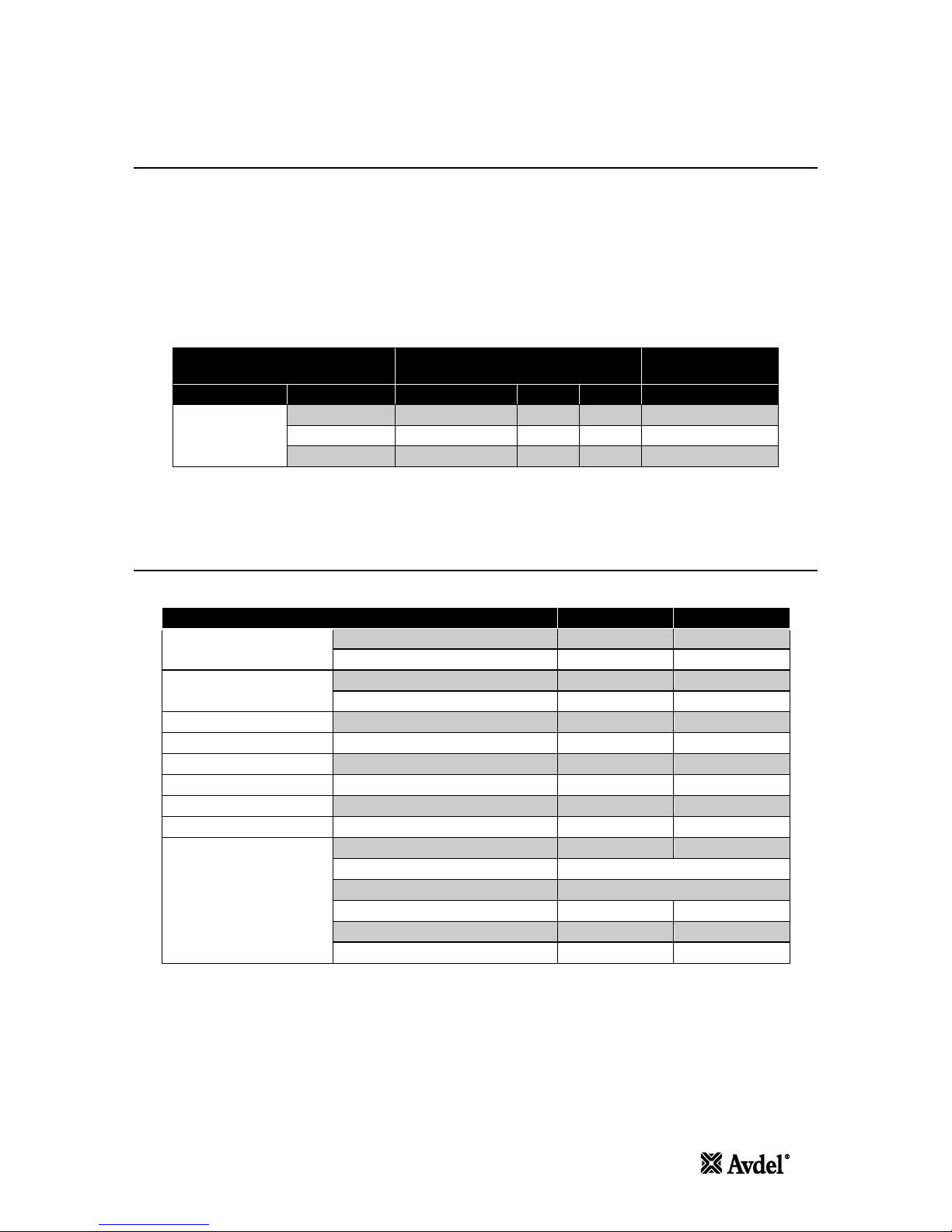
Refer to the table below for the list of applicable fasteners and associated nose equipment.
Refer to the datasheets listed in the table for the relevant nose assembly instructions.
FASTENER
NOSE ASSEMBLY
NOSE ASSEMBLY
DATASHEET
TYPE
SIZE
PART NUMBER DIM. 'A' DIM. 'B'
PART NUMBER
INFALOK®
7/8"
73410-03200
148 mm
70 mm
07900-00919
1"
73410-03100
152 mm
83 mm
07900-00919
1 1/8"
73410-03300
158 mm
83 mm
07900-00919
Refer to the illustration on page 6 for the identification of the nose assembly dimensions 'A' and 'B'.
The safety instructions must be followed at all times.
Placing Tool Specification
SPECIFICATION
METRIC
IMPERIAL
Force.
Pull at stated pull pressure
340.0 kN
76435.0 lbf
Push Off at stated return pressure
140.0 kN
31473.0 lbf
Pressure.
Pull
510 bar
7397 PSI
Return
200 bar
2901 PSI
Stroke:
Piston Stroke
55.0 mm
2.17 in
Weight:
Without nose equipment
13.5 kg
29.8 lb
Noise Level:
Less than
127 dB(A)
Vibration:
Less than
8.6 m/s2
27.5 it/s2
Hydraulic Oil:
Enerpac® Hydraulic Oil — HF-95X
Product Range:
Infalok®
22.2 to 28.6 mm
7/8 to 1-1/8 in
Additional Features.
Stem Ejection — Front or Rear
Front
Seal Arrangement
Lip and Wiper Seals
Hydraulic Bearing Rings
Yes — Front
Protective Handle / Hose Gator
Yes
Protective Hose Guard
Yes
Hose / Cable Retention Clamps
Yes
nAvder
5
5
Specification
Intent of Use
The AV™50 Installation Tool is principally a piston and cylinder assembly. When coupled hydraulically and electrically to
a compatible hydraulic power source and the relevant nose assembly is attached, it is then used to install 7/8” to 1 1/8”
Infalok® in Industrial Environments.
The placing tool and hydraulic pump unit may only be used in accordance with the operating instructions for placing
Avdel® fasteners.
Refer to the table below for the list of applicable fasteners and associated nose equipment.
Refer to the datasheets listed in the table for the relevant nose assembly instructions.
FASTENER
NOSE ASSEMBLY
NOSE ASSEMBLY
DATASHEET
TYPE
SIZE
PART NUMBER
DIM. ‘A’
DIM. ‘B’
PART NUMBER
INFALOK®
7/8”
73410-03200
148 mm
70 mm
07900-00919
1”
73410-03100
152 mm
83 mm
07900-00919
1 1/8”
73410-03300
158 mm
83 mm
07900-00919
Refer to the illustration on page 6 for the identification of the nose assembly dimensions ‘A’ and ‘B’.
The safety instructions must be followed at all times.
Placing Tool Specification
SPECIFICATION
METRIC
IMPERIAL
Force:
Pull at stated pull pressure
340.0 kN
76435.0 lbf
Push Off at stated return pressure
140.0 kN
31473.0 lbf
Pressure:
Pull
510 bar
7397 PSI
Return
200 bar
2901 PSI
Stroke:
Piston Stroke
55.0 mm
2.17 in
Weight:
Without nose equipment
13.5 kg
29.8 lb
Noise Level:
Less than
127 dB(A)
Vibration:
Less than
8.6 m/s²
27.5 ft/s²
Hydraulic Oil:
Enerpac® Hydraulic Oil – HF-95X
Product Range:
Infalok®
22.2 to 28.6 mm
7/8 to 1-1/8 in
Additional Features:
Stem Ejection – Front or Rear
Front
Seal Arrangement
Lip and Wiper Seals
Hydraulic Bearing Rings
Yes – Front
Protective Handle / Hose Gator
Yes
Protective Hose Guard
Yes
Hose / Cable Retention Clamps
Yes
HYDRAULIC HOSE ASSEMBLY
PART NUMBER
HOSE LENGTH
07008-00448
5 Metre
07008-00449
10 Metre
07008-00450
15 Metre
Specification
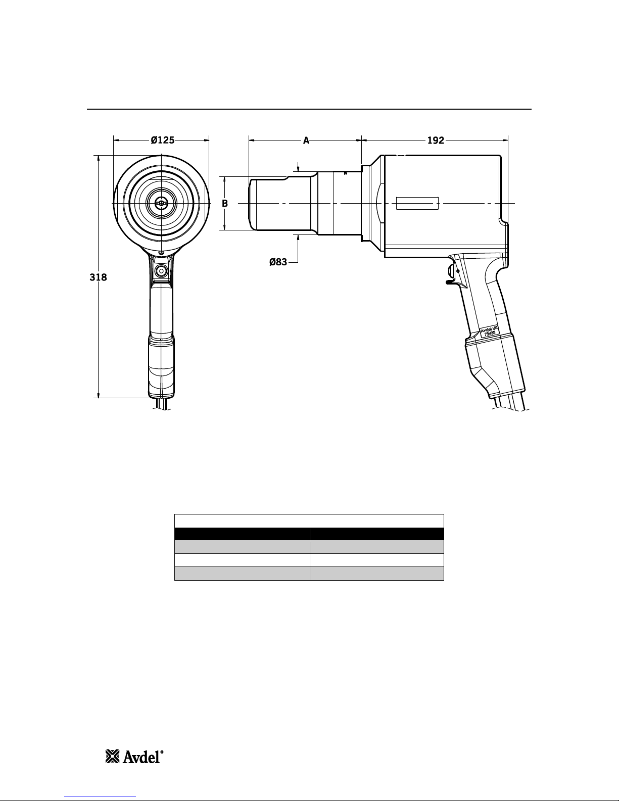
Placing Tool Dimensions
All dimensions are shown in millimetres.
Refer to the table on page 5 for the nose assembly dimensions 'A' and 'B'.
The tool is fitted with two Hydraulic Hoses and an electrical Control Cable, 0.6m in length. Additional hydraulic hose and
cable extension lengths are available to order separately as required. Refer to the table below for the available hose
assembly lengths and associated part numbers.
6
0
Avder
6
Specification
Placing Tool Dimensions
All dimensions are shown in millimetres.
Refer to the table on page 5 for the nose assembly dimensions ‘A’ and ‘B’.
The tool is fitted with two Hydraulic Hoses and an electrical Control Cable, 0.6m in length. Additional hydraulic hose and
cable extension lengths are available to order separately as required. Refer to the table below for the available hose
assembly lengths and associated part numbers.
HYDRAULIC HOSE ASSEMBLY
PART NUMBER
HOSE LENGTH
07008-00448
5 Metre
07008-00449
10 Metre
07008-00450
15 Metre

Putting Into Service
Principle of Operation
IMPORTANT - READ BOTH THE SAFETY INSTRUCTIONS ON PAGE 3 AND 4 AND THE PUMP UNIT INSTRUCTION
MANUAL CAREFULLY BEFORE PUTTING INTO SERVICE
When both hoses and control cable are connected to the Avder/Enerpac
®
hydraulic pump unit, the pull and return cycles
of the tool are controlled by depressing and releasing the trigger located in the handle.
When the switch is depressed the solenoid valve, located in the hydraulic pump unit, is energised and directs the
pressurised oil flow to the pull side of the piston in the placing tool. This also allows the oil in the return side of the
placing tool to return to the reservoir.
During the pull cycles the piston/collet assembly moves towards the rear of the tool allowing the 0-ring type cushion to
push the follower and jaws forward. If a fastener pin has been inserted in the nose assembly, the jaw set will clamp onto
the pintail and assembly will commence.
For Infalok® the cycle of installation will first clamp the joint to be fastened and then as the anvil continues to move
forward the collar will be swaged into the locking grooves of the pin. At the end of the swaging cycle the anvil will come
up against the joint and as movement continues the pintail will be broken off.
The trigger switch should be released immediately after pin break occurs.
If the trigger is not released, the piston will continue move towards the rear of the tool until it contacts the inner rear face.
When the piston reaches the end of the pull stroke, it uncovers flats on the rear end of a pressure relief valve rod. These
flats are designed to provide a passage for hydraulic fluid between the pull and return side of the piston. Thus allowing
pressurised fluid to be 'unloaded' or 'dumped' back to the reservoir, preventing unnecessary loading to the rear of the tool
body. The placing tool piston will be held in this position until the trigger is released.
Releasing the trigger switch will cause the solenoid to de-energise and reverse the flow of pressurised oil.
However, if during installation the pressure in the pull side achieves a preset 'High Pressure' value set at the pump. At
this point the solenoid valve will automatically de-energise and reverse the flow of pressurised oil to the return side of the
placing tool.
In either case, pressurised oil will now flow into the return side of the placing tool, with the oil in the pull side returning
to the reservoir.
The forward movement of the piston/collet assembly will eject the installed fastener from the anvil.
At the point of releasing the trigger or when the 'High Pressure' value is achieved, the solenoid valve will de-energise and
activate a preset 'Return Timer'. This controls the time that the pump motor will continue run before switching to the idle
mode. The timer can be manually set between 5 and 20 seconds to ensure that the placing tool piston always fully
returns to the forward position (refer to pump manual 07900-01030, pages 10 and 13).
When the piston returns to the fully forward position, the pressure will increase to preset low pressure value - c200bar.
The pump motor will continue to run until the Return Timer has expired. After this time period the motor will stop
automatically and valve will switch to the idle position. The solenoid valve will then automatically cycle to release
pressurised oil to the reservoir from both the pull and return side of the placing tool.
This keeps the installation tool in the forward position. No pressure will be present in the hydraulic system at this point.
The hydraulic pump unit will automatically start up on depression of the tool trigger switch.
nAvder
7
7
Putting Into Service
Principle of Operation
IMPORTANT - READ BOTH THE SAFETY INSTRUCTIONS ON PAGE 3 AND 4 AND THE PUMP UNIT INSTRUCTION
MANUAL CAREFULLY BEFORE PUTTING INTO SERVICE
When both hoses and control cable are connected to the Avdel®/Enerpac® hydraulic pump unit, the pull and return cycles
of the tool are controlled by depressing and releasing the trigger located in the handle.
When the switch is depressed the solenoid valve, located in the hydraulic pump unit, is energised and directs the
pressurised oil flow to the pull side of the piston in the placing tool. This also allows the oil in the return side of the
placing tool to return to the reservoir.
During the pull cycles the piston/collet assembly moves towards the rear of the tool allowing the O-ring type cushion to
push the follower and jaws forward. If a fastener pin has been inserted in the nose assembly, the jaw set will clamp onto
the pintail and assembly will commence.
For Infalok® the cycle of installation will first clamp the joint to be fastened and then as the anvil continues to move
forward the collar will be swaged into the locking grooves of the pin. At the end of the swaging cycle the anvil will come
up against the joint and as movement continues the pintail will be broken off.
The trigger switch should be released immediately after pin break occurs.
If the trigger is not released, the piston will continue move towards the rear of the tool until it contacts the inner rear face.
When the piston reaches the end of the pull stroke, it uncovers flats on the rear end of a pressure relief valve rod. These
flats are designed to provide a passage for hydraulic fluid between the pull and return side of the piston. Thus allowing
pressurised fluid to be ‘unloaded’ or ‘dumped’ back to the reservoir, preventing unnecessary loading to the rear of the tool
body. The placing tool piston will be held in this position until the trigger is released.
Releasing the trigger switch will cause the solenoid to de-energise and reverse the flow of pressurised oil.
However, if during installation the pressure in the pull side achieves a preset ‘High Pressure’ value set at the pump. At
this point the solenoid valve will automatically de-energise and reverse the flow of pressurised oil to the return side of the
placing tool.
In either case, pressurised oil will now flow into the return side of the placing tool, with the oil in the pull side returning
to the reservoir.
The forward movement of the piston/collet assembly will eject the installed fastener from the anvil.
At the point of releasing the trigger or when the ‘High Pressure’ value is achieved, the solenoid valve will de-energise and
activate a preset ‘Return Timer’. This controls the time that the pump motor will continue run before switching to the idle
mode. The timer can be manually set between 5 and 20 seconds to ensure that the placing tool piston always fully
returns to the forward position (refer to pump manual 07900-01030, pages 10 and 13).
When the piston returns to the fully forward position, the pressure will increase to preset low pressure value - c200bar.
The pump motor will continue to run until the Return Timer has expired. After this time period the motor will stop
automatically and valve will switch to the idle position. The solenoid valve will then automatically cycle to release
pressurised oil to the reservoir from both the pull and return side of the placing tool.
This keeps the installation tool in the forward position. No pressure will be present in the hydraulic system at this point.
The hydraulic pump unit will automatically start up on depression of the tool trigger switch.

Putting Into Service
Preparation for Use
CAUTION - CORRECT PULL AND RETURN PRESSURES ARE IMPORTANT FOR PROPER FUNCTION OF THE
ISTALLATION TOOL. PERSONAL INJURY OR DAMAGE TO EQUIPMENT MAY OCCUR WITHOUT CORRECT
PRESSURES. THE PULL AND RETURN PRESSURES SUPPLIED BY THE HYDRAULIC PUMP UNIT MUST NOT
EXCEED THOSE PRESSURES LISTED IN THE PLACING TOOL SPECIFICATION
IMPORTANT — BEFORE PUTTING THE PLACING TOOL AND HYDRAULIC HOSE SET INTO SERVICE:
ENSURE THAT THE PUMP PRESSURE RELIEF VALVES HAVE BEEN SET IN ACCORDANCE WITH THE PUMP
INSTRUCTIONS AND THE MAXIMUM PRESSURES SPECIFIED FOR THE PLACING TOOL AND HOSES.
ENSURE THAT THE HOSE KIT IS PRIMED WITH HYDRAULIC FLUID IN ACCORDANCE WITH THE PROCEDURE IN
THE PUMP INSTRUCTION MANUAL 07900-01030.
•
Ensure the mains power supply to the hydraulic pump unit is switched off.
•
Connect the placing tool hydraulic hose quick couplers directly to the pump unit before connecting the electrical
control cable. Hoses and control cable must be connected in this order and disconnected in reverse order.
•
Switch on the mains supply to the hydraulic pump unit. Wait 5 seconds for the pump unit to complete the boot
sequence, before pressing the trigger switch. When all set the LCD screen on the pump unit will display
'AVDEL'.
•
During the boot sequence the pump control system identifies any trigger operation as a potential malfunction
and prevents the motor from starting. The LCD screen will display 'BUTTON FAULT' in this instance. Reset by
switching off the power supply for 10 seconds.
•
Ensure that the placing tool is positioned below the pump reservoir tanks. Depress the placing tool trigger
switch and allow the tool to achieve full stroke. Continue to depress the trigger to hold the tool in this position
for 30 seconds to circulate hydraulic fluid and expel any air from the tool. Repeat the process three times.
•
Observe action of tool. Check for fluid leaks and ensure that in the idler mode the piston is in the fully forward
position. The placing tool will now be primed.
•
Switch off the mains power supply to the hydraulic pump unit and then disconnect the placing tool from the
pump unit in reverse order to that described above.
•
Now connect the placing tool to the primed hydraulic hose kit and electrical control cable. Then connect
hydraulic hose kit quick couplers and the electrical control cable to the pump unit.
•
Attach the nose assembly to the tool as per the instructions in the relevant nose assembly datasheet.
•
Switch on the mains supply to the hydraulic pump unit as described above.
•
Depress and release the placing tool trigger switch a few times to the full stroke of the tool to circulate hydraulic
fluid.
•
The placing tool is now ready for use.
8
0
Avder
8
Putting Into Service
Preparation for Use
CAUTION - CORRECT PULL AND RETURN PRESSURES ARE IMPORTANT FOR PROPER FUNCTION OF THE
ISTALLATION TOOL. PERSONAL INJURY OR DAMAGE TO EQUIPMENT MAY OCCUR WITHOUT CORRECT
PRESSURES. THE PULL AND RETURN PRESSURES SUPPLIED BY THE HYDRAULIC PUMP UNIT MUST NOT
EXCEED THOSE PRESSURES LISTED IN THE PLACING TOOL SPECIFICATION
IMPORTANT – BEFORE PUTTING THE PLACING TOOL AND HYDRAULIC HOSE SET INTO SERVICE:
ENSURE THAT THE PUMP PRESSURE RELIEF VALVES HAVE BEEN SET IN ACCORDANCE WITH THE PUMP
INSTRUCTIONS AND THE MAXIMUM PRESSURES SPECIFIED FOR THE PLACING TOOL AND HOSES.
ENSURE THAT THE HOSE KIT IS PRIMED WITH HYDRAULIC FLUID IN ACCORDANCE WITH THE PROCEDURE IN
THE PUMP INSTRUCTION MANUAL 07900-01030.
Ensure the mains power supply to the hydraulic pump unit is switched off.
Connect the placing tool hydraulic hose quick couplers directly to the pump unit before connecting the electrical
control cable. Hoses and control cable must be connected in this order and disconnected in reverse order.
Switch on the mains supply to the hydraulic pump unit. Wait 5 seconds for the pump unit to complete the boot
sequence, before pressing the trigger switch. When all set the LCD screen on the pump unit will display
‘AVDEL’.
During the boot sequence the pump control system identifies any trigger operation as a potential malfunction
and prevents the motor from starting. The LCD screen will display ‘BUTTON FAULT’ in this instance. Reset by
switching off the power supply for 10 seconds.
Ensure that the placing tool is positioned below the pump reservoir tanks. Depress the placing tool trigger
switch and allow the tool to achieve full stroke. Continue to depress the trigger to hold the tool in this position
for 30 seconds to circulate hydraulic fluid and expel any air from the tool. Repeat the process three times.
Observe action of tool. Check for fluid leaks and ensure that in the idler mode the piston is in the fully forward
position. The placing tool will now be primed.
Switch off the mains power supply to the hydraulic pump unit and then disconnect the placing tool from the
pump unit in reverse order to that described above.
Now connect the placing tool to the primed hydraulic hose kit and electrical control cable. Then connect
hydraulic hose kit quick couplers and the electrical control cable to the pump unit.
Attach the nose assembly to the tool as per the instructions in the relevant nose assembly datasheet.
Switch on the mains supply to the hydraulic pump unit as described above.
Depress and release the placing tool trigger switch a few times to the full stroke of the tool to circulate hydraulic
fluid.
The placing tool is now ready for use.
 Loading...