

Page 1

Title page
Nortel Communication Server 1000
Nortel Communication Server 1000 Release 4.5
IP Phones
Description, Installation, and Operation
Document Number: 553-3001-368
Document Release: Standard 7.00
Date: August 2005
Year Publish FCC TM
Copyright © Nortel Networks Limited 2005
All Rights Reserved
Produced in Canada
Information is subject to change without notice. Nortel Networks reserves the right to make changes in design
or components as progress in engineering and manufacturing may warrant.
Nortel, Nortel (Logo), the Globemark, This is the Way, This is Nortel (Design mark), SL-1, Meridian 1, and
Succession are trademarks of Nortel Networks.
Page 2

Page 3

4
Page 3 of 430
Revision history
August 2005
Standard 7.00. This document is up-issued to support CS 1000 Release 4.5.
April 2005
Standard 6.00. This document is up-issued to support the addition of the
IP Phone 2007.
April 2005
Standard 5.00. This document is up-issued to support the addition of the
IP Audio Conference Phone 2033.
February 2005
Standard 4.00. This document is up-issued to support the 8.x Firmware
Upgrade for IP Phones.
September 2004
June 2004
October 2003
Standard 3.00. This document is up-issued to support Communication Server
1000 Release 4.0.
Standard 2.00. This document is up-issued to include the Nortel Networks
Mobile Voice Client 2050.
Standard 1.00. This document is a new NTP for Succession 3.0 Software. It
was created to support a restructuring of the Documentation Library. This
document contains information previously contained in the following legacy
document, now retired: Internet Terminals Description (553-3001-217).
IP Phones Description, Installation, and Operation
Page 4

Page 4 of 430 Revision history
553-3001-368 Standard 7.00 August 2005
Page 5

12
Page 5 of 430
Contents
List of procedures . . . . . . . . . . . . . . . . . . . . . . . . . . 13
About this document . . . . . . . . . . . . . . . . . . . . . . . 21
Subject .. . . . . . . . . . . . . . . . . . . . . . . . . . . . . . . . . . . . . . . . . . . . . . . . . 21
Applicable systems . . . . . . . . . . . . . . . . . . . . . . . . . . . . . . . . . . . . . . . . 22
Intended audience . . . . . . . . . . . . . . . . . . . . . . . . . . . . . . . . . . . . . . . . . 23
Conventions .. . . . . . . . . . . . . . . . . . . . . . . . . . . . . . . . . . . . . . . . . . . . . 23
Related information .. . . . . . . . . . . . . . . . . . . . . . . . . . . . . . . . . . . . . . . 24
Nortel IP Phone 2001 . . . . . . . . . . . . . . . . . . . . . . . . 27
Contents .. . . . . . . . . . . . . . . . . . . . . . . . . . . . . . . . . . . . . . . . . . . . . . . . 27
Introduction . . . . . . . . . . . . . . . . . . . . . . . . . . . . . . . . . . . . . . . . . . . . . . 27
Description . . . . . . . . . . . . . . . . . . . . . . . . . . . . . . . . . . . . . . . . . . . . . . 28
Supported features .. . . . . . . . . . . . . . . . . . . . . . . . . . . . . . . . . . . . . . . . 32
Features not currently supported . . . . . . . . . . . . . . . . . . . . . . . . . . . . . . 32
Display characteristics .. . . . . . . . . . . . . . . . . . . . . . . . . . . . . . . . . . . . . 33
Key number assignments . . . . . . . . . . . . . . . . . . . . . . . . . . . . . . . . . . . 35
Package components . . . . . . . . . . . . . . . . . . . . . . . . . . . . . . . . . . . . . . . 37
Before you begin . . . . . . . . . . . . . . . . . . . . . . . . . . . . . . . . . . . . . . . . . . 38
First-time installation . . . . . . . . . . . . . . . . . . . . . . . . . . . . . . . . . . . . . . 40
Start-up sequence . . . . . . . . . . . . . . . . . . . . . . . . . . . . . . . . . . . . . . . . . 52
Full Duplex mode . . . . . . . . . . . . . . . . . . . . . . . . . . . . . . . . . . . . . . . . . 53
Gratuitous Address Resolution Protocol Protection . . . . . . . . . . . . . . . 55
IP Phones Description, Installation, and Operation
Page 6

Page 6 of 430 Contents
Extensible Authentication Protocol . . . . . . . . . . . . . . . . . . . . . . . . . . . 55
Reinstalling an IP Phone 2001 . . . . . . . . . . . . . . . . . . . . . . . . . . . . . . . 55
Replacing an IP Phone 2001 . . . . . . . . . . . . . . . . . . . . . . . . . . . . . . . . 57
Removing an IP Phone 2001 from service . . . . . . . . . . . . . . . . . . . . . . 57
Nortel IP Phone 2002 . . . . . . . . . . . . . . . . . . . . . . . 59
Contents . . . . . . . . . . . . . . . . . . . . . . . . . . . . . . . . . . . . . . . . . . . . . . . . 59
Introduction .. . . . . . . . . . . . . . . . . . . . . . . . . . . . . . . . . . . . . . . . . . . . . 60
Description . . . . . . . . . . . . . . . . . . . . . . . . . . . . . . . . . . . . . . . . . . . . . . 60
Supported features . . . . . . . . . . . . . . . . . . . . . . . . . . . . . . . . . . . . . . . . 65
Features not currently supported .. . . . . . . . . . . . . . . . . . . . . . . . . . . . . 66
Display characteristics . . . . . . . . . . . . . . . . . . . . . . . . . . . . . . . . . . . . . 67
Key number assignments . . . . . . . . . . . . . . . . . . . . . . . . . . . . . . . . . . . 69
Package components .. . . . . . . . . . . . . . . . . . . . . . . . . . . . . . . . . . . . . . 70
Before you begin .. . . . . . . . . . . . . . . . . . . . . . . . . . . . . . . . . . . . . . . . . 72
First-time installation . . . . . . . . . . . . . . . . . . . . . . . . . . . . . . . . . . . . . . 73
Startup sequence . . . . . . . . . . . . . . . . . . . . . . . . . . . . . . . . . . . . . . . . . . 87
Full Duplex mode . . . . . . . . . . . . . . . . . . . . . . . . . . . . . . . . . . . . . . . . . 88
Gratuitous Address Resolution Protocol Protection . . . . . . . . . . . . . . . 90
Extensible Authentication Protocol . . . . . . . . . . . . . . . . . . . . . . . . . . . 90
Reinstalling an IP Phone 2002 . . . . . . . . . . . . . . . . . . . . . . . . . . . . . . . 90
Replacing an IP Phone 2002 . . . . . . . . . . . . . . . . . . . . . . . . . . . . . . . . 91
Removing an IP Phone 2002 from service . . . . . . . . . . . . . . . . . . . . . . 92
Nortel IP Phone 2004 . . . . . . . . . . . . . . . . . . . . . . . 93
Contents . . . . . . . . . . . . . . . . . . . . . . . . . . . . . . . . . . . . . . . . . . . . . . . . 93
Introduction .. . . . . . . . . . . . . . . . . . . . . . . . . . . . . . . . . . . . . . . . . . . . . 94
Description . . . . . . . . . . . . . . . . . . . . . . . . . . . . . . . . . . . . . . . . . . . . . . 94
Supported features . . . . . . . . . . . . . . . . . . . . . . . . . . . . . . . . . . . . . . . . 99
Features not currently supported .. . . . . . . . . . . . . . . . . . . . . . . . . . . . . 100
Display characteristics . . . . . . . . . . . . . . . . . . . . . . . . . . . . . . . . . . . . . 101
553-3001-368 Standard 7.00 August 2005
Page 7

Contents Page 7 of 430
Key number assignments . . . . . . . . . . . . . . . . . . . . . . . . . . . . . . . . . . . 103
Package components . . . . . . . . . . . . . . . . . . . . . . . . . . . . . . . . . . . . . . . 105
Before you begin . . . . . . . . . . . . . . . . . . . . . . . . . . . . . . . . . . . . . . . . . . 107
First-time installation . . . . . . . . . . . . . . . . . . . . . . . . . . . . . . . . . . . . . . 108
Startup sequence . . . . . . . . . . . . . . . . . . . . . . . . . . . . . . . . . . . . . . . . . . 122
Full Duplex mode . . . . . . . . . . . . . . . . . . . . . . . . . . . . . . . . . . . . . . . . . 123
Gratuitous Address Resolution Protocol Protection . . . . . . . . . . . . . . . 125
Extensible Authentication Protocol . . . . . . . . . . . . . . . . . . . . . . . . . . . 125
Reinstalling an IP Phone 2004 . . . . . . . . . . . . . . . . . . . . . . . . . . . . . . . 125
Replacing an IP Phone 2004 . . . . . . . . . . . . . . . . . . . . . . . . . . . . . . . . 126
Removing an IP Phone 2004 from service . . . . . . . . . . . . . . . . . . . . . . 127
Nortel IP Phone 2007 . . . . . . . . . . . . . . . . . . . . . . . . 129
Contents .. . . . . . . . . . . . . . . . . . . . . . . . . . . . . . . . . . . . . . . . . . . . . . . . 129
Introduction . . . . . . . . . . . . . . . . . . . . . . . . . . . . . . . . . . . . . . . . . . . . . . 130
Description . . . . . . . . . . . . . . . . . . . . . . . . . . . . . . . . . . . . . . . . . . . . . . 130
Key number assignments . . . . . . . . . . . . . . . . . . . . . . . . . . . . . . . . . . . 145
Package components . . . . . . . . . . . . . . . . . . . . . . . . . . . . . . . . . . . . . . . 147
Before you begin . . . . . . . . . . . . . . . . . . . . . . . . . . . . . . . . . . . . . . . . . . 148
First-time installation . . . . . . . . . . . . . . . . . . . . . . . . . . . . . . . . . . . . . . 150
Startup sequence . . . . . . . . . . . . . . . . . . . . . . . . . . . . . . . . . . . . . . . . . . 165
Full Duplex mode . . . . . . . . . . . . . . . . . . . . . . . . . . . . . . . . . . . . . . . . . 166
Gratuitous Address Resolution Protocol Protection . . . . . . . . . . . . . . . 168
Reinstalling an IP Phone 2007 . . . . . . . . . . . . . . . . . . . . . . . . . . . . . . . 168
Replacing an IP Phone 2007 . . . . . . . . . . . . . . . . . . . . . . . . . . . . . . . . . 170
Removing an IP Phone 2007 from service . . . . . . . . . . . . . . . . . . . . . . 170
IP Phone
Key Expansion Module (KEM) . . . . . . . . . . . . . . . . 171
Contents .. . . . . . . . . . . . . . . . . . . . . . . . . . . . . . . . . . . . . . . . . . . . . . . . 171
Description . . . . . . . . . . . . . . . . . . . . . . . . . . . . . . . . . . . . . . . . . . . . . . 171
IP Phones Description, Installation, and Operation
Page 8

Page 8 of 430 Contents
Features .. . . . . . . . . . . . . . . . . . . . . . . . . . . . . . . . . . . . . . . . . . . . . . . . 172
Display characteristics . . . . . . . . . . . . . . . . . . . . . . . . . . . . . . . . . . . . . 173
Key number assignments . . . . . . . . . . . . . . . . . . . . . . . . . . . . . . . . . . . 173
Package components .. . . . . . . . . . . . . . . . . . . . . . . . . . . . . . . . . . . . . . 173
Configuration . . . . . . . . . . . . . . . . . . . . . . . . . . . . . . . . . . . . . . . . . . . . 174
Installation . . . . . . . . . . . . . . . . . . . . . . . . . . . . . . . . . . . . . . . . . . . . . . 178
IP Phone KEM startup initialization .. . . . . . . . . . . . . . . . . . . . . . . . . . 180
Operating parameters . . . . . . . . . . . . . . . . . . . . . . . . . . . . . . . . . . . . . . 181
Nortel IP Softphone 2050 . . . . . . . . . . . . . . . . . . . . 185
Contents . . . . . . . . . . . . . . . . . . . . . . . . . . . . . . . . . . . . . . . . . . . . . . . . 185
Introduction .. . . . . . . . . . . . . . . . . . . . . . . . . . . . . . . . . . . . . . . . . . . . . 185
Description . . . . . . . . . . . . . . . . . . . . . . . . . . . . . . . . . . . . . . . . . . . . . . 186
System components . . . . . . . . . . . . . . . . . . . . . . . . . . . . . . . . . . . . . . . 187
Operating parameters . . . . . . . . . . . . . . . . . . . . . . . . . . . . . . . . . . . . . . 206
Implementation . . . . . . . . . . . . . . . . . . . . . . . . . . . . . . . . . . . . . . . . . . . 207
Operation . . . . . . . . . . . . . . . . . . . . . . . . . . . . . . . . . . . . . . . . . . . . . . . 209
Installation . . . . . . . . . . . . . . . . . . . . . . . . . . . . . . . . . . . . . . . . . . . . . . 220
Configuration utility . . . . . . . . . . . . . . . . . . . . . . . . . . . . . . . . . . . . . . . 224
Running the IP Softphone 2050 for the first time .. . . . . . . . . . . . . . . . 245
Changing the TN of an existing IP Softphone 2050 . . . . . . . . . . . . . . . 246
Removing an IP Softphone 2050 from service . . . . . . . . . . . . . . . . . . . 246
Nortel Mobile Voice Client 2050 . . . . . . . . . . . . . . 247
Contents . . . . . . . . . . . . . . . . . . . . . . . . . . . . . . . . . . . . . . . . . . . . . . . . 247
Introduction .. . . . . . . . . . . . . . . . . . . . . . . . . . . . . . . . . . . . . . . . . . . . . 247
Description . . . . . . . . . . . . . . . . . . . . . . . . . . . . . . . . . . . . . . . . . . . . . . 248
System components . . . . . . . . . . . . . . . . . . . . . . . . . . . . . . . . . . . . . . . 249
Application software .. . . . . . . . . . . . . . . . . . . . . . . . . . . . . . . . . . . . . . 251
MVC 2050 Call Handling screen . . . . . . . . . . . . . . . . . . . . . . . . . . . . . 252
Operating parameters . . . . . . . . . . . . . . . . . . . . . . . . . . . . . . . . . . . . . . 271
553-3001-368 Standard 7.00 August 2005
Page 9

Contents Page 9 of 430
Operation .. . . . . . . . . . . . . . . . . . . . . . . . . . . . . . . . . . . . . . . . . . . . . . . 272
MVC 2050 installation . . . . . . . . . . . . . . . . . . . . . . . . . . . . . . . . . . . . . 273
MVC 2050 removal .. . . . . . . . . . . . . . . . . . . . . . . . . . . . . . . . . . . . . . . 275
Configuration . . . . . . . . . . . . . . . . . . . . . . . . . . . . . . . . . . . . . . . . . . . . 276
MVC 2050 and WLAN .. . . . . . . . . . . . . . . . . . . . . . . . . . . . . . . . . . . . 293
Nortel WLAN Handset 2210
and WLAN Handset 2211 . . . . . . . . . . . . . . . . . . . . 295
Contents .. . . . . . . . . . . . . . . . . . . . . . . . . . . . . . . . . . . . . . . . . . . . . . . . 295
Introduction . . . . . . . . . . . . . . . . . . . . . . . . . . . . . . . . . . . . . . . . . . . . . . 295
Description . . . . . . . . . . . . . . . . . . . . . . . . . . . . . . . . . . . . . . . . . . . . . . 295
Supported features .. . . . . . . . . . . . . . . . . . . . . . . . . . . . . . . . . . . . . . . . 300
Features not currently supported . . . . . . . . . . . . . . . . . . . . . . . . . . . . . . 300
Display characteristics .. . . . . . . . . . . . . . . . . . . . . . . . . . . . . . . . . . . . . 301
Key number assignments . . . . . . . . . . . . . . . . . . . . . . . . . . . . . . . . . . . 301
Dedicated keys . . . . . . . . . . . . . . . . . . . . . . . . . . . . . . . . . . . . . . . . . . . 302
Package components . . . . . . . . . . . . . . . . . . . . . . . . . . . . . . . . . . . . . . . 304
Before you begin . . . . . . . . . . . . . . . . . . . . . . . . . . . . . . . . . . . . . . . . . . 308
Installation and configuration . . . . . . . . . . . . . . . . . . . . . . . . . . . . . . . . 308
Nortel IP Audio Conference Phone 2033 . . . . . . . . 309
Contents .. . . . . . . . . . . . . . . . . . . . . . . . . . . . . . . . . . . . . . . . . . . . . . . . 309
Introduction . . . . . . . . . . . . . . . . . . . . . . . . . . . . . . . . . . . . . . . . . . . . . . 310
Description . . . . . . . . . . . . . . . . . . . . . . . . . . . . . . . . . . . . . . . . . . . . . . 310
Extension microphones . . . . . . . . . . . . . . . . . . . . . . . . . . . . . . . . . . . . . 311
Diagnostic Utilities . . . . . . . . . . . . . . . . . . . . . . . . . . . . . . . . . . . . . . . . 315
Supported features .. . . . . . . . . . . . . . . . . . . . . . . . . . . . . . . . . . . . . . . . 315
Display characteristics .. . . . . . . . . . . . . . . . . . . . . . . . . . . . . . . . . . . . . 315
Key number assignments . . . . . . . . . . . . . . . . . . . . . . . . . . . . . . . . . . . 318
Package components . . . . . . . . . . . . . . . . . . . . . . . . . . . . . . . . . . . . . . . 319
Before you begin . . . . . . . . . . . . . . . . . . . . . . . . . . . . . . . . . . . . . . . . . . 321
IP Phones Description, Installation, and Operation
Page 10

Page 10 of 430 Contents
First time installation . . . . . . . . . . . . . . . . . . . . . . . . . . . . . . . . . . . . . . 322
Startup sequence . . . . . . . . . . . . . . . . . . . . . . . . . . . . . . . . . . . . . . . . . . 335
Full Duplex mode . . . . . . . . . . . . . . . . . . . . . . . . . . . . . . . . . . . . . . . . . 336
Gratuitous Address Resolution Protocol Protection . . . . . . . . . . . . . . . 337
Replacing an IP Audio Conference Phone 2033 . . . . . . . . . . . . . . . . . 339
Removing an IP Audio Conference Phone 2033 from service . . . . . . . 340
Connecting an extension microphone .. . . . . . . . . . . . . . . . . . . . . . . . . 340
SIP Phone . . . . . . . . . . . . . . . . . . . . . . . . . . . . . . . . 341
Contents . . . . . . . . . . . . . . . . . . . . . . . . . . . . . . . . . . . . . . . . . . . . . . . . 341
Introduction .. . . . . . . . . . . . . . . . . . . . . . . . . . . . . . . . . . . . . . . . . . . . . 341
SIP Phone features . . . . . . . . . . . . . . . . . . . . . . . . . . . . . . . . . . . . . . . . 343
Installation and configuration overview . . . . . . . . . . . . . . . . . . . . . . . . 344
Features overview . . . . . . . . . . . . . . . . . . . . . . . . . 345
Contents . . . . . . . . . . . . . . . . . . . . . . . . . . . . . . . . . . . . . . . . . . . . . . . . 345
Introduction .. . . . . . . . . . . . . . . . . . . . . . . . . . . . . . . . . . . . . . . . . . . . . 345
Corporate Directory . . . . . . . . . . . . . . . . . . . . . . . . . . . . . . . . . . . . . . . 346
Personal Directory . . . . . . . . . . . . . . . . . . . . . . . . . . . . . . . . . . . . . . . . 346
Redial List .. . . . . . . . . . . . . . . . . . . . . . . . . . . . . . . . . . . . . . . . . . . . . . 346
Callers List . . . . . . . . . . . . . . . . . . . . . . . . . . . . . . . . . . . . . . . . . . . . . . 346
Password Administration . . . . . . . . . . . . . . . . . . . . . . . . . . . . . . . . . . . 347
IP Call Recording . . . . . . . . . . . . . . . . . . . . . . . . . . . . . . . . . . . . . . . . . 347
Virtual Office . . . . . . . . . . . . . . . . . . . . . . . . . . . . . . . . . . . . . . . . . . . . 347
Emergency Services for Virtual Office . . . . . . . . . . . . . . . . . . . . . . . . 347
Appendix A: Specifications . . . . . . . . . . . . . . . . . . 349
Contents . . . . . . . . . . . . . . . . . . . . . . . . . . . . . . . . . . . . . . . . . . . . . . . . 349
Environmental specifications . . . . . . . . . . . . . . . . . . . . . . . . . . . . . . . . 351
Appendix B: 802.1Q VLAN description . . . . . . . . 353
Contents . . . . . . . . . . . . . . . . . . . . . . . . . . . . . . . . . . . . . . . . . . . . . . . . 353
553-3001-368 Standard 7.00 August 2005
Page 11

Contents Page 11 of 430
Introduction . . . . . . . . . . . . . . . . . . . . . . . . . . . . . . . . . . . . . . . . . . . . . . 353
Description . . . . . . . . . . . . . . . . . . . . . . . . . . . . . . . . . . . . . . . . . . . . . . 354
IP Phone support . . . . . . . . . . . . . . . . . . . . . . . . . . . . . . . . . . . . . . . . . . 354
IP Softphone 2050 support . . . . . . . . . . . . . . . . . . . . . . . . . . . . . . . . . . 356
Three-port switch support . . . . . . . . . . . . . . . . . . . . . . . . . . . . . . . . . . . 356
VLAN IDs . . . . . . . . . . . . . . . . . . . . . . . . . . . . . . . . . . . . . . . . . . . . . . . 357
.. . . . . . . . . . . . . . . . . . . . . . . . . . . . . . . . . . . . . . . . . . . . . . . . . . . . . . . 359
Appendix C: 802.1x Port-based network access
control . . . . . . . . . . . . . . . . . . . . . . . . . . . . . . . . . . . 361
Contents .. . . . . . . . . . . . . . . . . . . . . . . . . . . . . . . . . . . . . . . . . . . . . . . . 361
Introduction . . . . . . . . . . . . . . . . . . . . . . . . . . . . . . . . . . . . . . . . . . . . . . 361
Extensible Authentication Protocol .. . . . . . . . . . . . . . . . . . . . . . . . . . . 361
Appendix D: IP Phone diagnostic utilities . . . . . . 367
Contents .. . . . . . . . . . . . . . . . . . . . . . . . . . . . . . . . . . . . . . . . . . . . . . . . 367
Introduction . . . . . . . . . . . . . . . . . . . . . . . . . . . . . . . . . . . . . . . . . . . . . . 367
IP Phone Diagnostics . . . . . . . . . . . . . . . . . . . . . . . . . . . . . . . . . . . . . . 367
Using CLI Commands .. . . . . . . . . . . . . . . . . . . . . . . . . . . . . . . . . . . . . 397
Configure IP Phone 2007 Local Options . . . . . . . . . . . . . . . . . . . . . . . 400
Appendix E: TFTP Server . . . . . . . . . . . . . . . . . . . . 409
Introduction . . . . . . . . . . . . . . . . . . . . . . . . . . . . . . . . . . . . . . . . . . . . . . 409
TFTP Server planning . . . . . . . . . . . . . . . . . . . . . . . . . . . . . . . . . . . . . . 409
Appendix F: Active Call Failover . . . . . . . . . . . . . . 417
Index . . . . . . . . . . . . . . . . . . . . . . . . . . . . . . . . . . . . . 419
IP Phones Description, Installation, and Operation
Page 12

Page 12 of 430 Contents
553-3001-368 Standard 7.00 August 2005
Page 13

20
Page 13 of 430
List of procedures
Procedure 1
Pre-installation checklist . . . . . . . . . . . . . . . . . . . . . . . . 39
Procedure 2
Installing an IP Phone 2001 for the first time using
manual configuration . . . . . . . . . . . . . . . . . . . . . . . . . . .41
Procedure 3
Installing an IP Phone 2001 for the first time
using DHCP . . . . . . . . . . . . . . . . . . . . . . . . . . . . . . . . . . .47
Procedure 4
Disabling Auto Negotiate and enabling Full Duplex
mode . . . . . . . . . . . . . . . . . . . . . . . . . . . . . . . . . . . . . . . . .54
Procedure 5
Checking Ethernet Statistics . . . . . . . . . . . . . . . . . . . . . 54
Procedure 6
Changing the TN of an existing IP Phone 2001 . . . . . . 56
Procedure 7
Replacing an IP Phone 2001 . . . . . . . . . . . . . . . . . . . . . . 57
Procedure 8
Removing an IP Phone 2001 from service . . . . . . . . . . 57
Procedure 9
Pre-installation checklist . . . . . . . . . . . . . . . . . . . . . . . . 72
IP Phones Description, Installation, and Operation
Page 14

Page 14 of 430 List of procedures
Procedure 10
Installing an IP Phone 2002 for the first time using
manual configuration . . . . . . . . . . . . . . . . . . . . . . . . . . . 75
Procedure 11
Installing an IP Phone 2002 for the first time
using DHCP . . . . . . . . . . . . . . . . . . . . . . . . . . . . . . . . . . . 80
Procedure 12
Disabling Auto Negotiate and enabling Full Duplex
mode . . . . . . . . . . . . . . . . . . . . . . . . . . . . . . . . . . . . . . . . . 89
Procedure 13
Checking Ethernet Statistics . . . . . . . . . . . . . . . . . . . . . 89
Procedure 14
Changing the TN of an existing IP Phone 2002 . . . . . . 90
Procedure 15
Replacing an IP Phone 2002 . . . . . . . . . . . . . . . . . . . . . 91
Procedure 16
Removing an IP Phone 2002 from service . . . . . . . . . . 92
Procedure 17
Pre-installation checklist . . . . . . . . . . . . . . . . . . . . . . . . 107
Procedure 18
Installing an IP Phone 2004 for the first time using
manual configuration . . . . . . . . . . . . . . . . . . . . . . . . . . . 110
Procedure 19
Installing an IP Phone 2004 for the first time
using DHCP . . . . . . . . . . . . . . . . . . . . . . . . . . . . . . . . . . . 116
Procedure 20
Disabling Auto Negotiate and enabling Full Duplex
mode . . . . . . . . . . . . . . . . . . . . . . . . . . . . . . . . . . . . . . . . . 124
553-3001-368 Standard 7.00 August 2005
Page 15

List of procedures Page 15 of 430
Procedure 21
Checking Ethernet Statistics . . . . . . . . . . . . . . . . . . . . . 124
Procedure 22
Changing the TN of an existing IP Phone 2004 . . . . . . 125
Procedure 23
Replacing an IP Phone 2004 . . . . . . . . . . . . . . . . . . . . . 126
Procedure 24
Removing an IP Phone 2004 from service . . . . . . . . . . 127
Procedure 25
Pre-installation checklist . . . . . . . . . . . . . . . . . . . . . . . . 149
Procedure 26
Installing an IP Phone 2007 for the first time using
manual configuration . . . . . . . . . . . . . . . . . . . . . . . . . . .151
Procedure 27
Installing an IP Phone 2007 for the first time
using DHCP . . . . . . . . . . . . . . . . . . . . . . . . . . . . . . . . . . .158
Procedure 28
Disabling Auto Negotiate and enabling Full Duplex
mode . . . . . . . . . . . . . . . . . . . . . . . . . . . . . . . . . . . . . . . . .167
Procedure 29
Checking Ethernet Statistics . . . . . . . . . . . . . . . . . . . . . 167
Procedure 30
Changing the TN of an existing IP Phone 2007 . . . . . . 169
Procedure 31
Replacing an IP Phone 2007 . . . . . . . . . . . . . . . . . . . . . . 170
Procedure 32
Removing an IP Phone 2007 from service . . . . . . . . . . 170
IP Phones Description, Installation, and Operation
Page 16

Page 16 of 430 List of procedures
Procedure 33
Connecting the IP Phone KEM to an IP Phone 2002 or
IP Phone 2004 . . . . . . . . . . . . . . . . . . . . . . . . . . . . . . . . . 179
Procedure 34
Installing an IP Softphone 2050 . . . . . . . . . . . . . . . . . . . 207
Procedure 35
Installing the USB Headset Adapter . . . . . . . . . . . . . . . 221
Procedure 36
Installing the IP Softphone 2050 on your PC
(New installation) . . . . . . . . . . . . . . . . . . . . . . . . . . . . . .222
Procedure 37
Upgrading the IP Softphone 2050 on your PC
(for Windows 2000 and Windows XP users only) . . . . 222
Procedure 38
Upgrading the IP Softphone 2050 on your PC
(for Windows 98 platforms) . . . . . . . . . . . . . . . . . . . . . . 223
Procedure 39
Changing the TN of an existing IP Softphone 2050 . . . 246
Procedure 40
Removing an IP Softphone 2050 from service . . . . . . . 246
Procedure 41
Starting MVC 2050 . . . . . . . . . . . . . . . . . . . . . . . . . . . . . . 272
Procedure 42
Synchronizing a PDA with a desktop PC
using ActiveSync . . . . . . . . . . . . . . . . . . . . . . . . . . . . . . 273
Procedure 43
Installing MVC 2050 . . . . . . . . . . . . . . . . . . . . . . . . . . . . 274
Procedure 44
Removing MVC 2050 from your PDA . . . . . . . . . . . . . . 275
553-3001-368 Standard 7.00 August 2005
Page 17

List of procedures Page 17 of 430
Procedure 45
Enable Auto-Create . . . . . . . . . . . . . . . . . . . . . . . . . . . . .281
Procedure 46
Disabling Automatic Gain Control . . . . . . . . . . . . . . . . . 287
Procedure 47
Pre-installation checklist . . . . . . . . . . . . . . . . . . . . . . . . 321
Procedure 48
Installing an IP Audio Conference Phone 2033
for the first time using manual configuration . . . . . . . . 323
Procedure 49
Installing an IP Audio Conference Phone 2033
for the first time using DHCP . . . . . . . . . . . . . . . . . . . . . 331
Procedure 50
Disabling Auto Negotiate and enabling
Full Duplex mode . . . . . . . . . . . . . . . . . . . . . . . . . . . . . .337
Procedure 51
Changing the TN of an existing
IP Audio Conference Phone 2033 . . . . . . . . . . . . . . . . . 338
Procedure 52
Replacing an IP Audio Conference Phone 2033 . . . . . . 339
Procedure 53
Removing an IP Audio Conference Phone 2033
from service . . . . . . . . . . . . . . . . . . . . . . . . . . . . . . . . . . .340
Procedure 54
Connecting an extension microphone to the
IP Audio Conference Phone 2033 . . . . . . . . . . . . . . . . . 340
Procedure 55
Enable the 802.1x supplicant . . . . . . . . . . . . . . . . . . . . . 362
IP Phones Description, Installation, and Operation
Page 18

Page 18 of 430 List of procedures
Procedure 56
Disabling 802.1x supplicant . . . . . . . . . . . . . . . . . . . . . . 364
Procedure 57
Accessing the Network Diagnostic Tools
menu in Local mode . . . . . . . . . . . . . . . . . . . . . . . . . . . . 372
Procedure 58
Executing Ping . . . . . . . . . . . . . . . . . . . . . . . . . . . . . . . . 372
Procedure 59
Executing TraceRoute . . . . . . . . . . . . . . . . . . . . . . . . . . 373
Procedure 60
Accessing Ethernet Statistics . . . . . . . . . . . . . . . . . . . . 373
Procedure 61
Accessing IP Network Statistics . . . . . . . . . . . . . . . . . . 373
Procedure 62
Accessing IP Set & DHCP Information . . . . . . . . . . . . . 374
Procedure 63
Accessing the Diagnostics submenu
in Remote Mode . . . . . . . . . . . . . . . . . . . . . . . . . . . . . . . 374
Procedure 64
Accessing Diagnostic Tools in Remote mode . . . . . . . 375
Procedure 65
Entering an IP address . . . . . . . . . . . . . . . . . . . . . . . . . . 375
Procedure 66
Changing the number of Pings . . . . . . . . . . . . . . . . . . . 376
Procedure 67
Pinging an IP address . . . . . . . . . . . . . . . . . . . . . . . . . . . 376
Procedure 68
Reviewing the results of the Ping . . . . . . . . . . . . . . . . . 377
553-3001-368 Standard 7.00 August 2005
Page 19

List of procedures Page 19 of 430
Procedure 69
Entering an IP address . . . . . . . . . . . . . . . . . . . . . . . . . .377
Procedure 70
Changing the number of Hops . . . . . . . . . . . . . . . . . . . .378
Procedure 71
Tracing a route . . . . . . . . . . . . . . . . . . . . . . . . . . . . . . . .378
Procedure 72
Reviewing the results of the trace . . . . . . . . . . . . . . . . .378
Procedure 73
Browsing Ethernet Statistics . . . . . . . . . . . . . . . . . . . . .379
Procedure 74
Checking 802.1x Supplicant status . . . . . . . . . . . . . . . . 379
Procedure 75
Checking 802.1x Supplicant Authentication
state . . . . . . . . . . . . . . . . . . . . . . . . . . . . . . . . . . . . . . . . .380
Procedure 76
Checking Device ID . . . . . . . . . . . . . . . . . . . . . . . . . . . . .380
Procedure 77
Checking Authenticator ID . . . . . . . . . . . . . . . . . . . . . . . 380
Procedure 78
Browsing IP Statistics . . . . . . . . . . . . . . . . . . . . . . . . . . . 381
Procedure 79
Browsing RUDP Statistics . . . . . . . . . . . . . . . . . . . . . . .382
Procedure 80
Browsing Quality of Service Statistics . . . . . . . . . . . . . 382
Procedure 81
Accessing NAT information . . . . . . . . . . . . . . . . . . . . . .396
IP Phones Description, Installation, and Operation
Page 20

Page 20 of 430 List of procedures
Procedure 82
Displaying Network Configuration information . . . . . . 401
Procedure 83
Using Network Diagnostic Tools . . . . . . . . . . . . . . . . . . 402
Procedure 84
Using Ethernet Statistics tool . . . . . . . . . . . . . . . . . . . . 404
Procedure 85
Using the IP Network Statistics tool . . . . . . . . . . . . . . . 405
Procedure 86
Using the IPSet&DHCP Information tool . . . . . . . . . . . . 407
Procedure 87
Upgrade the firmware . . . . . . . . . . . . . . . . . . . . . . . . . . . 411
553-3001-368 Standard 7.00 August 2005
Page 21

26
Page 21 of 430
About this document
This document is a global document. Contact your system supplier or your
Nortel representative to verify that the hardware and software described are
supported in your area.
Subject
This document contains description, installation, and administration
information for the following:
• Nortel IP Audio Conference Phone 2033
• Nortel IP Phone 2001, IP Phone 2002, IP Phone 2004, and IP Phone 2007
• Nortel IP Phone Key Expansion Module (KEM)
• Nortel IP Softphone 2050
• Nortel Mobile Voice Client 2050 for Personal Digital Assistants (PDAs)
• Nortel WLAN Handset 2210 and WLAN Handset 2211
Note on legacy products and releases
This NTP contains information about systems, components, and features that
are compatible with Nortel Communication Server 1000 Release 4.5
software. For more information on legacy products and releases, click the
Technical Documentation link under Support & Training on the Nortel
home page:
www.nortel.com
Note:
IP Phones Description, Installation, and Operation
Page 22

Page 22 of 430 About this document
Applicable systems
This document applies to the following systems:
• Communication Server 1000S (CS 1000S)
• Communication Server 1000M Chassis (CS 1000M Chassis)
• Communication Server 1000M Cabinet (CS 1000M Cabinet)
• Communication Server 1000M Half Group (CS 1000M HG)
• Communication Server 1000M Single Group (CS 1000M SG)
• Communication Server 1000M Multi Group (CS 1000M MG)
• Communication Server 1000E (CS 1000E)
• Meridian 1 PBX 11C Chassis (Meridian 1 PBX 11C Chassis)
• Meridian 1 PBX 11C Cabinet (Meridian 1 PBX 11C Cabinet)
• Meridian 1 PBX 51C
• Meridian 1 PBX 61C
•Meridian1 PBX81
• Meridian 1 PBX 81C
Note: When upgrading software, memory upgrades may be required on
the Signaling Server, the Call Server, or both.
System migration
When particular Meridian 1 systems are upgraded to run CS 1000
Release 4.5 software and configured to include a Signaling Server, they
become CS 1000M systems. Table 1 lists each Meridian 1 system that
supports an upgrade path to a CS 1000M system.
Table 1
Meridian 1 systems to CS 1000M systems (Part 1 of 2)
This Meridian 1 system... Maps to this CS 1000M system
Meridian 1 PBX 11C Chassis CS 1000M Chassis
Meridian 1 PBX 11C Cabinet CS 1000M Cabinet
553-3001-368 Standard 7.00 August 2005
Page 23

Table 1
Meridian 1 systems to CS 1000M systems (Part 2 of 2)
This Meridian 1 system... Maps to this CS 1000M system
Meridian 1 PBX 51C CS 1000M Half Group
Meridian 1 PBX 61C CS 1000M Single Group
Meridian 1 PBX 81 CS 1000M Multi Group
Meridian 1 PBX 81C CS 1000M Multi Group
For more information, see one or more of the following NTPs:
• Communication Server 1000M and Meridian 1: Small System Upgrade
Procedures (553-3011-258)
• Communication Server 1000M and Meridian 1: Large System Upgrade
Procedures (553-3021-258)
• Communication Server 1000S: Upgrade Procedures (553-3031-258)
• Communication Server 1000E: Upgrade Procedures (553-3041-258)
Intended audience
About this document Page 23 of 430
Conventions
This document is intended for individuals responsible for maintaining
Internet Enabled systems.
Terminology
In this document, the following systems are referred to generically as
“system”:
• Communication Server 1000S (CS 1000S)
• Communication Server 1000M (CS 1000M)
• Communication Server 1000E (CS 1000E)
•Meridian1
IP Phones Description, Installation, and Operation
Page 24

Page 24 of 430 About this document
The following systems are referred to generically as “Small System”:
• Communication Server 1000M Chassis (CS 1000M Chassis)
• Communication Server 1000M Cabinet (CS 1000M Cabinet)
• Meridian 1 PBX 11C Chassis
• Meridian 1 PBX 11C Cabinet
The following systems are referred to generically as “Large System”:
• Communication Server 1000M Half Group (CS 1000M HG)
• Communication Server 1000M Single Group (CS 1000M SG)
• Communication Server 1000M Multi Group (CS 1000M MG)
• Meridian 1 PBX 51C
• Meridian 1 PBX 61C
•Meridian1 PBX81
• Meridian 1 PBX 81C
Related information
This section lists information sources that relate to this document.
NTPs
The following NTPs and documents are referenced in this document:
• IP Phone 2001 User Guide
• IP Phone 2002 User Guide
• IP Phone 2004 User Guide
• IP Phone 2007 User Guide
• IP Audio Conference Phone 2033 User Guide
• IP Phone Key Expansion Module User Guide
• Mobile Voice Client 2050 User Guide
• WLAN Handset 2210 User Guide
553-3001-368 Standard 7.00 August 2005
Page 25

About this document Page 25 of 430
• WLAN Handset 2211 User Guide
• Converging the Data Network with VoIP (553-3001-160)
• IP Peer Networking: Installation and Configuration (553-3001-213)
• WLAN IP Telephony: Installation and Configuration (553-3001-304)
• Features and Services (553-3001-306)
• Software Input/Output: Administration (553-3001-311)
• IP Line: Description, Installation, and Operation (553-3001-365)
• Software Input/Output: Maintenance (553-3001-511)
Online
To access Nortel documentation online, click the Technical Documentation
link under Support & Training on the Nortel home page:
www.nortel.com
CD-ROM
To obtain Nortel documentation on CD-ROM, contact your Nortel customer
representative.
IP Phones Description, Installation, and Operation
Page 26

Page 26 of 430 About this document
553-3001-368 Standard 7.00 August 2005
Page 27

58
Page 27 of 430
Nortel IP Phone 2001
Contents
This section contains information on the following topics:
Introduction . . . . . . . . . . . . . . . . . . . . . . . . . . . . . . . . . . . . . . . . . . . . . . 27
Description . . . . . . . . . . . . . . . . . . . . . . . . . . . . . . . . . . . . . . . . . . . . . . 28
Supported features. . . . . . . . . . . . . . . . . . . . . . . . . . . . . . . . . . . . . . . . . 32
Features not currently supported . . . . . . . . . . . . . . . . . . . . . . . . . . . . . . 32
Display characteristics. . . . . . . . . . . . . . . . . . . . . . . . . . . . . . . . . . . . . . 33
Key number assignments . . . . . . . . . . . . . . . . . . . . . . . . . . . . . . . . . . . 35
Package components . . . . . . . . . . . . . . . . . . . . . . . . . . . . . . . . . . . . . . . 37
Before you begin . . . . . . . . . . . . . . . . . . . . . . . . . . . . . . . . . . . . . . . . . . 38
First-time installation . . . . . . . . . . . . . . . . . . . . . . . . . . . . . . . . . . . . . . 40
Start-up sequence . . . . . . . . . . . . . . . . . . . . . . . . . . . . . . . . . . . . . . . . . 52
Full Duplex mode . . . . . . . . . . . . . . . . . . . . . . . . . . . . . . . . . . . . . . . . . 53
Gratuitous Address Resolution Protocol Protection . . . . . . . . . . . . . . . 55
Replacing an IP Phone 2001 . . . . . . . . . . . . . . . . . . . . . . . . . . . . . . . . . 57
Removing an IP Phone 2001 from service . . . . . . . . . . . . . . . . . . . . . . 57
Introduction
This section explains how to install and maintain the IP Phone 2001. For
information on using the IP Phone 2001, see the IP Phone 2001 User Guide.
IP Phones Description, Installation, and Operation
Page 28

Page 28 of 430 Nortel IP Phone 2001
This section contains the following procedures:
• Procedure 1, “Pre-installation checklist” on page 39.
• Procedure 2, “Installing an IP Phone 2001 for the first time using manual
configuration” on page 41.
• Procedure 3, “Installing an IP Phone 2001 for the first time using DHCP”
on page 47.
• Procedure 4, “Disabling Auto Negotiate and enabling Full Duplex
mode” on page 54.
• Procedure 5, “Checking Ethernet Statistics” on page 54.
• Procedure 6, “Changing the TN of an existing IP Phone 2001” on
page 56.
• Procedure 7, “Replacing an IP Phone 2001” on page 57.
• Procedure 8, “Removing an IP Phone 2001 from service” on page 57.
Note: After an IP Phone has been installed and configured, if power to
the phone is interrupted, re-entry of the IP parameters, Node Number,
TN, or re-acquisition of firmware is not required.
Description
The IP Phone 2001 brings voice and data to the desktop environment. It
connects directly to the LAN through the Ethernet connection.
The IP Phone 2001 components are shown in Figure 1 on page 29 and
described in Table 2 on page 29.
553-3001-368 Standard 7.00 August 2005
Page 29
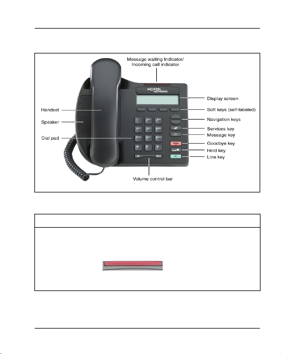
Figure 1
IP Phone 2001
Nortel IP Phone 2001 Page 29 of 430
Table 2
IP Phone 2001 components and functions (Part 1 of 3)
Component Function
Speaker Press the Dial/Line key to activate
the speaker for on-hook dialing and
listening.
Message Waiting/
Incoming Call Indicator
IP Phones Description, Installation, and Operation
The Message Waiting lamp turns ON
to indicate that a message has been
left for the user. This lamp also
flashes when the set ringer is ON.
Page 30
Page 30 of 430 Nortel IP Phone 2001
Table 2
IP Phone 2001 components and functions (Part 2 of 3)
Component Function
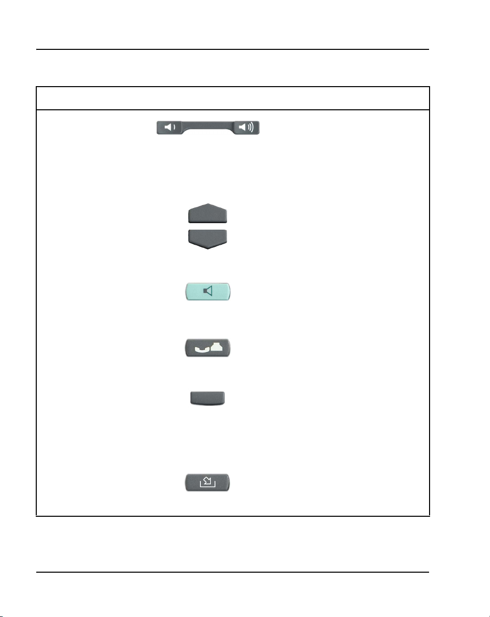
Volume control bar Use the volume control bar to adjust
the volume of the Handset, Ringer,
and On-hook Dialing/Listen tones.
Press the right side of the rocker bar
to increase volume; press the left side
to decrease volume.
Navigation keys Use the navigation keys to scroll
through menus and lists in the display
area.
Dial/Line key Use the Dial/Line key to access the
single line and activate on-hook
dialing. No status icon or LED is
provided.
Hold key Press the Hold key to put an active
call on hold. Press the Dial/Line key
to return to the caller on hold.
Soft keys (self-labeled) Soft keys (self-labeled) are located
below the display area. The LCD
label above the key changes, based
on the active feature.
Note: A triangle before a key label
indicates that the key is active.
Message key Press the Message key to access
your voicemail box.
553-3001-368 Standard 7.00 August 2005
Page 31

Nortel IP Phone 2001 Page 31 of 430
Table 2
IP Phone 2001 components and functions (Part 3 of 3)
Component Function
Goodbye key Press the Goodbye key to terminate
an active call.
Services key Press the Services key to access the
following items:
• Telephone Options (see Notes 1
and 2):
— Volume adjustment
— Contrast adjustment
— Language
— Date/Time
— Local DialPad Tone
— Set Information
— Ring type
• Password Admin:
— Station Control Password
• Virtual Office Login and Virtual
Office Logout (if Virtual Office is
configured)
Press the Services key to exit from
any menu or menu item.
Note 1: If a call is presented while the user is manipulating information, the phone rings.
However, the screen display is not updated with Caller ID and the programming text is not
disturbed.
Note 2: The user can originate a call using Autodial or Last Number Redial while manipulating
an option. However, the display is not updated with the dialed digits or Caller ID, and Autodial
and Last Number Redial intercept the dialpad.
IP Phones Description, Installation, and Operation
Page 32

Page 32 of 430 Nortel IP Phone 2001
Supported features
The IP Phone 2001 supports the following additional features:
• 802.1Q VLAN and 802.1P priority support, industry standards for
managing bandwidth usage
• 802.1x Port-based network access control, industry standard for passing
Extensible Authentication Protocol (EAP) over a LAN
• Extensible Authentication Protocol (EAP)
• Gratuitous Address Resolution Protocol Protection (GARP)
• VLAN filtering
• Virtual office
•Branch Office
• Both the registered and configured TNs are displayed in the Set Info
menu.
• Basic IP User License — for more information, see IP Line: Description,
Installation, and Operation (553-3001-365)
• language support: English, French, Swedish, Danish, Norwegian,
German, Dutch, Portuguese, Czech, Finnish, Hungarian, Italian, Polish,
Spanish, Japanese, Russian, Latvian, Turkish
Features not currently supported
The following features are not supported on the IP Phone 2001:
• External three-port switch to support sharing LAN access with a PC or
other data device is not provided. However, the IP Phone 2001 does
provide 100 Mbps full-duplex support.
• Integrated switch
• Personal Directory, Call Log and Redial List are not supported.
However, if the primary DN on an IP Phone 2001 is an MADN of an IP
Phone 2002, IP Phone 2004, or IP Softphone 2050, Preferred Name
Match and Idle Set Display (new call indication) are supported.
• Corporate Directory
553-3001-368 Standard 7.00 August 2005
Page 33

• Automatic Call Distribution
• IP Key Expansion Modules
• Support of accessory modules
• Live Dialpad
• Group Listening
• Set-to-Set messaging
• Context-sensitive soft keys
• Handsfree operation
• Headset support
• External Applications Server
Display characteristics
An IP Phone 2001 has two display areas:
• information line display
• soft key label display
Nortel IP Phone 2001 Page 33 of 430
Figure 2 on page 34 shows these two display areas.
IP Phones Description, Installation, and Operation
Page 34

Page 34 of 430 Nortel IP Phone 2001
Figure 2
IP Phone 2001 display areas
Cleaning the IP Phone display screen
Gently wipe the IP Phone display screen with a soft, dry cloth.
CAUTION
Do not use any liquids or powders on the IP Phone 2001.
Using anything other than a soft, dry cloth can
contaminate IP Phone components and cause premature
failure.
Information Line display
An IP Phone 2001 has a one-line information display area with the following
information:
• Caller Number
•Caller Name
• Feature prompt strings
553-3001-368 Standard 7.00 August 2005
Page 35

• User-entered digits
• Date and time information (if the IP Phone is in an idle state)
• Set information
The information area changes, according to call processing state and active
features.
Soft key label display
A maximum of ten functions can be assigned to the soft keys. Your system
administrator assigns functions to the soft keys in layers.
Use the More.. soft key to navigate through the layers of functions. If there
are only four functions assigned to the soft keys, the More.. key does not
appear and all four functions are displayed.
The soft key label has a maximum six characters. Each soft key includes the
soft key label and an icon. When a soft key is in use, a flashing icon displays
at the beginning of the soft key label, and the label shifts one character to the
right. (If the label is six characters long, the last or rightmost character is
truncated.) If a feature is enabled, the icon state turns to On. It remains in the
on state until the feature key is pressed again. This cancels the enabled feature
and turns the icon off, returning the soft key label to its original state.
Nortel IP Phone 2001 Page 35 of 430
Key number assignments
The IP Phone 2001 has four soft-labeled, predefined soft keys that are used to
provide up to ten features. Because they are predefined, the user cannot
change the key number assignment.
The Message key is numbered 16. Key numbers 17 to 31 are the four soft key
labels below the display area. See Figure 1 on page 29.
Key numbers 17 to 31 support the features A03, A06, CFW, CHG, CPN,
PRK, PRS, RGA, RNP, SCC, SCU, SSC, SSU and TRN, as listed in Table 3
on page 36.
IP Phones Description, Installation, and Operation
Page 36

Page 36 of 430 Nortel IP Phone 2001
Key number assignments at the Call Server are aligned with that of the
IP Phone 2002. The mappings between IP Phone 2001 soft key numbers and
PBX CPU key numbers are the same as on the IP Phone 2002 and IP Phone
2004.
Table 3 describes the IP Phone assignment functions for each of the soft keys.
Use LD 11 to program keys 16 to 26 on the IP Phone 2001.
Note: If you attempt to configure anything other than the permitted
response, the system generates an error code.
Table 3
IP Phone 2001 soft keys
Key Number Response Description
Key 16 MWK Message Waiting key
Key 17 TRN Call Transfer key
Key 18 A06 Six-party conference key
Alternate: A03 (3-party conference)
Key 19 CFW Call Forward key
Key 20 RGA Ring Again key
Key 21 PRK Call Park key
Key 22 RNP Ringing Number Pickup key
Key 23 Reserved for speed dial Speed dial includes SCU, SCC, SSU,
SSC
Key 24 PRS Privacy Release key
Key 25 CHG Charge Account key
Key 26 CPN Calling Party Number key
Keys 27 - 31 Reserved
553-3001-368 Standard 7.00 August 2005
Page 37

Package components
The following information applies to Phase II IP Phones. Product codes for
Phase II IP Phones are different from previous sets.
See the product code on the back of the phone to confirm whether it is a Phase
II IP Phone. The product code for Phase II IP Phones appears as “IP Phone
200x”. The product code for previous versions of the IP Phones appears with
an “i” in front of the model number; example, “i200x”.
The AC power adapter must be ordered separately if local power using the
AC adapter is required, because Phase II IP Phones include integrated support
for a number of power over LAN options, including support for IEEE 802.3af
standard power.
Nortel IP Phone 2001 Page 37 of 430
Table 4 lists the IP Phone 2001 package components and product codes.
Table 4
IP Phone 2001 components list (Part 1 of 2)
IP Phone 2001 package contents include:
• IP Phone 2001
• Handset
• Handset cord
• Footstand
• 7 ft. Cat5 Ethernet cable
• Getting Started card
IP Phone 2001(Ethergray) with Icon keycaps NTDU90AA16/A0533387
IP Phone 2001 (Ethergray) with English text label keycaps NTDU90BA16/A0533388
IP Phone 2001 (Charcoal) with Icon keycaps NTDU90AA70/A0053389
IP Phone 2001 (Charcoal) with English text label keycaps NTDU90BA70/A0533390
Replacement parts
7 ft. Cat5 Ethernet Cable A0648375
IP Phones Description, Installation, and Operation
Page 38

Page 38 of 430 Nortel IP Phone 2001
Table 4
IP Phone 2001 components list (Part 2 of 2)
Handset, Ethergray A0788874
Handset, Charcoal A0758634
Handset cord, Ethergray; for IP Phone 2004 and IP Phone 2001 A088682
Handset cord, Charcoal; for IP Phone 2004 and IP Phone 2001 N0000764
IP Phone 2001/2002/2004 Power Adapters
Power transformer (117/120 VAC 50/60 Hz) (North America) A0619627
Power transformer 3 prong AC to AC, direct plug-in, 8W, 240
VAC, 50Hz to 16 VAC at 500 mA (Ireland and UK)
Power transformer AC to AC, direct plug-in, 8W, 230 VAC, 50/60
Hz, to 16 VAC at 500 mA (Europe)
Power transformer 2 prong wall plug direct plug-in AC to AC, 8W,
240 VAC, 50 Hz, to 16 VAC at 500 mA (Australia and New
Zealand)
Power transformer AC to AC, direct plug-in, 8W, 100 VAC, 50
Hz, to 16 VAC at 500 mA
For more information, and for information about previous versions of the IP
Phone, contact your Nortel representative.
Before you begin
The following section provides a step-by-step guide through the
IP Phone 2001 installation process. Before installing the IP Phone 2001,
complete the following pre-installation checklist.
A0656598
A0619635
A0647042
A0828858
553-3001-368 Standard 7.00 August 2005
Page 39

Nortel IP Phone 2001 Page 39 of 430
Procedure 1
Pre-installation checklist
1 Ensure there is one IP Phone 2001 boxed package for each IP Phone
2001 being installed. The package contains:
• IP Phone 2001
• Handset
• Handset cord
• Footstand
• 2.3 m (7 foot) Cat5 Ethernet cable
• Getting Started card
2 To install and configure an IP Phone 2001, the host system must be
installed with the Voice Gateway Media Card.
3 If an AC power adapter is required, ensure the correct AC power
transformer is used. The voltage rating of the transformer must match the
wall outlet voltage. Refer to Table 4 on page 37.
4 Understand the three configuration modes that you can choose as you
proceed through the installation of the IP Phone 2001. The three
configuration modes are:
• Static IP address
• Dynamic Partial DHCP – see “Dynamic IP address assignment —
Partial DHCP” on page 40.
• Dynamic Full DHCP – see “Dynamic IP address assignment — Full
DHCP” on page 41.
5 Make sure that a DHCP server and DHCP relay agents, if required, are
installed, configured, and running.
– see “Static IP address assignment” on page 40.
End of Procedure
IP Phones Description, Installation, and Operation
Page 40

Page 40 of 430 Nortel IP Phone 2001
First-time installation
CAUTION — Damage to Equipment
Do not plug your IP Phone 2001 into an ISDN
connection. Severe damage can result. Consult your
system administrator to ensure that you are plugging
your IP Phone into a 10/100BaseT Ethernet jack.
IP address assignments
During the first-time installation, there are IP address parameters that are
entered either manually or automatically depending on the installation
configuration. As well, you are prompted to enable or disable 802.1Q. For
more information, see “802.1Q VLAN description” on page 353.
There are three configuration modes you can choose from to obtain the IP
parameters. Review the following sections for more information on the
configuration mode that you are using.
Static IP address assignment
During the installation, the IP Phone 2001 parameters are entered manually
using the key pad.
Your system administrator provides the following information: IP address,
subnet mask, and default Media Gateway.
You must also enter the Connect Server parameters including: IP address,
port number, action, and retry count.
Go to Procedure 2, “Installing an IP Phone 2001 for the first time using
manual configuration” on page 41.
Dynamic IP address assignment
For a partial DHCP installation, you must provide, through the IP Phone 2001
key pad, the Connect Server parameters including: IP address, port number,
action, and retry count. Other parameters (IP Phone IP address, subnet mask,
and default Gateway) are retrieved from the DHCP server.
553-3001-368 Standard 7.00 August 2005
— Partial DHCP
Page 41

Nortel IP Phone 2001 Page 41 of 430
The IP Phone 2001 password, node ID and TN must be entered manually
from the key pad.
For more information about DHCP servers, see Converging the Data
Network with VoIP (553-3001-160).
Go to Procedure 3, “Installing an IP Phone 2001 for the first time using
DHCP” on page 47.
Dynamic IP address assignment
— Full DHCP
For a full DHCP installation, all parameters (IP Phone IP address, subnet
mask, default Gateway, Connect Server IP address, port number, action, and
retry count) are retrieved from the DHCP server to recognize the IP Phone
2001.
The IP Phone 2001 password, node ID, and TN must be entered manually
from the key pad.
For more information on how to set up DHCP servers for use with the
IP Phones, refer to Converging the Data Network with VoIP (553-3001-160).
Go to Procedure 3, “Installing an IP Phone 2001 for the first time using
DHCP” on page 47.
Procedure 2
Installing an IP Phone 2001 for the first time using
manual configuration
1 Configure a virtual loop on the system using LD 97.
For more information, see Software Input/Output: Administration
(553-3001-311).
2 Configure the IP Phone 2001 on the system using LD 11.
For more information, see Software Input/Output: Administration
(553-3001-311).
3 Connect the IP Phone 2001 components:
a. Connect one end of the handset cord to the handset jack on the back
of the IP Phone identified with a handset icon.
b. Connect the other end of the handset cord to the handset.
IP Phones Description, Installation, and Operation
Page 42

Page 42 of 430 Nortel IP Phone 2001
4 Connect one end of the CAT5 Ethernet cable to the network interface
located on the back of the IP Phone (identified with a LAN icon, see
Figure 3). The other end of the CAT5 Ethernet cable plugs into the IP
network.
Figure 3
IP Phone 2001 rear view
553-3001-368 Standard 7.00 August 2005
Page 43

Nortel IP Phone 2001 Page 43 of 430
5 Power the IP Phone 2001 using either the Power over Ethernet or an AC
power transformer (local power).
If local power is used, plug the AC power transformer into the nearest
power outlet. Make sure you use the correct AC power transformer is
used. The voltage rating of the transformer must match the wall outlet
voltage. Refer to Table 4 on page 37. Connect the transformer to the
AC power jack shown in Figure 3 on page 42. Be sure to thread the
cord around the retaining hook to provide strain relief for a secure
power connection.
IMPORTANT!
Timing information
There are only four seconds between plugging in the IP Phone 2001
power transformer and the appearance of the Nortel logo in the middle
of the display. When you see the logo, you have one second to respond
by pressing the four feature keys at the bottom of the display in
sequence from left to right. If you miss the one-second response time,
the IP Phone 2001 attempts to locate the connect server. Wait until it is
finished, and then begin the power-up sequence again.
6 When the Nortel logo appears in the middle of the display, immediately
press the four feature keys at the bottom of the display in sequence from
left to right.
7 At the prompt EAP enable?, select Yes. Enter DeviceID and Password.
For more information on EAP, refer to
network access control” on page 361
Note: If you select No, you will not be prompted to enter Device ID and
Password.
8 At the prompt DHCP Yes/No?, select No.
9 Enter the following information provided by your system administrator:
Appendix C: “802.1x Port-based
.
Screen prompt Description
set IP A valid IP Phone 2001 IP address
net msk A subnet mask
def gw The default Gateway for the IP Phone 2001 on
the LAN segment to which it is connected
IP Phones Description, Installation, and Operation
Page 44

Page 44 of 430 Nortel IP Phone 2001
10 Enter the information for the primary Connect Server (S1) and the
secondary Connect Server (S2):
Screen prompt Description
S1 IP The node IP address of the IP line
S1 Port This is a fixed value: 4100
S1 action This is a fixed value: 1
S1 retry The number of times the IP Phone
S2 IP Same as S1 in most cases (see
S2 Port Same as S1
S2 action Same as S1
S2 retry Same as S1
Cfg XAS? (0-No,1-Yes) Enter 0 (for No)
node
attempts to connect to the
2001
server. Enter 10.
note below)
External Application Server (XAS)
is not supported on the IP Phone
2001. This prompt exists to support
future implementation of XAS.
VLAN? (0-No, 1-Ma, 2-Au) Default 0 (for No)
553-3001-368 Standard 7.00 August 2005
802.1Q VLAN remains off and
initialization continues.
For more information about VLAN
configuration, refer to Converging
the Data Network with VoIP
(553-3001-160).
Page 45

Nortel IP Phone 2001 Page 45 of 430
1-Ma
Enter a Voice VLAN ID, then press
OK.
The following Voice VLAN ID
displays:
Manual Cfg
VOICE VLAN ID: 1234
Note: The Voice VLAN ID is
entered as an integer. The Voice
VLAN ID is a 12-bit value between
1 and 4095.
The IP Phone 2001 is configured
with 802.1Q enabled, the VOICE
VLAN ID is configured to the
entered value, and the VOICE
VLAN priority = 6.
2-Au
Automatically enter a VLAN ID
using DHCP. DHCP auto discovers
the VLAN ID.
) VLANFiLTER (0-No, 1-Yes)
Default 0 (for No)
You will not be prompted for
VLANFILTER if VLAN? is not
enabled.
Data VLAN? (0-No, 1-Yes) After the value is entered, the DATA
VLAN configuration option appears
on the display.
Select 0-No, since DATA VLAN is
not supported on the IP Phone
2001.
Duplex (0-Auto, 1-Full) Default 0 (for Auto)
GARP Ignore? (0-No,1-Yes) Default 0 (for No)
IP Phones Description, Installation, and Operation
Page 46

Page 46 of 430 Nortel IP Phone 2001
11 The IP Phone 2001 can support primary (S1) and secondary (S2) connect
server. If you require IP Phones to register on multiple nodes, refer to
“Enhanced Redundancy for IP Line Nodes” in IP Line: Description,
Installation, and Operation (553-3001-365).
The IP Phone 2001 searches for the connect server. When the
connection is complete, proceed with step 12.
12 Enter the following information provided by your system administrator:
Screen prompt Description
Password IP Phone Installer Password
Node The node ID.
TN The TN or VTN.
The IP Phone 2001 registers with the Terminal Proxy Server (TPS) and,
if needed, begins the firmware download. This takes several minutes.
When the download is complete, the IP Phone 2001 resets.
Note: The Enhanced UNIStim Firmware Download feature for IP Phones
provides an improved method of delivering new firmware to IP Phones.
For further information on Enhanced UNIStim Firmware Download, refer
to IP Line: Description, Installation, and Operation (553-3001-365).
The current system date and time appear on the top line of the display
when the configuration is complete. Self-labeling keys also appear.
13 Check for dial tone and the correct DN above the display.
14 Secure the IP Phone footstand to the base of the IP Phone. Use the angle
adjustment grip on the top back of the IP Phone to adjust the position.
15 (Optional) Customize the feature keys as required. For more information,
see IP Phone 2001 User Guide.
You are not prompted to enter the IP Phone
Installer Password if it has not been configured
in your system.
553-3001-368 Standard 7.00 August 2005
End of Procedure
Page 47

Nortel IP Phone 2001 Page 47 of 430
Procedure 3
Installing an IP Phone 2001 for the first time
using DHCP
1 Configure a virtual loop on the system using LD 97.
For more information, see Software Input/Output: Administration
(553-3001-311).
2 Configure the IP Phone 2001 on the system using LD 11.
For more information, see Software Input/Output: Administration
(553-3001-311).
3 Connect the IP Phone 2001 components:
a. Connect one end of the handset cord to the handset jack on the back
of the IP Phone identified with a handset icon.
b. Connect the other end of the handset cord to the handset.
4 Connect one end of the CAT5 Ethernet cable to the network interface
located on the back of the IP Phone (identified with a LAN icon, see
Figure 3 on page 42). The other end of the CAT5 Ethernet cable plugs
into the IP network.
IP Phones Description, Installation, and Operation
Page 48

Page 48 of 430 Nortel IP Phone 2001
5 Power the IP Phone 2001 using either the Power over Ethernet or an AC
power transformer (local power).
To use local power, plug the AC power transformer into the nearest
power outlet. Ensure the correct AC power transformer is used. The
voltage rating of the transformer must match the wall outlet voltage.
Refer to Table 4 on page 37. Connect the transformer to the AC power
jack shown in Figure 3 on page 42. Be sure to thread the cord around
the retaining hook to provide strain relief for a secure power
connection.
Timing information
There are only four seconds between plugging in the IP Phone 2001
power transformer and the appearance of the Nortel logo in the middle
of the display area. When you see the logo, you have one second to
respond by pressing the four feature keys at the bottom of the display in
sequence from left to right. If you miss the one-second response time,
the IP Phone 2001 attempts to locate the connect server. Wait until it is
finished, and then begin the power-up sequence again.
6 When the Nortel logo appears in the middle of the display area,
immediately press the four feature keys at the bottom of the display in
sequence from left to right.
7 At the prompt EAP enable?, select Yes. Enter DeviceID and Password.
For more information on EAP, refer to Appendix C: “802.1x Port-based
network access control” on page 361.
Note: If you select No, you will not be prompted to enter Device ID and
Password.
8 At the prompt DHCP Yes/No?, select Yes.
9 Select Partial or Full DHCP.
IMPORTANT!
a. If you select Full DHCP, then the following parameters are retrieved
from the DHCP server:
— a valid IP Phone 2001 IP address
— a subnet mask
553-3001-368 Standard 7.00 August 2005
Page 49

Nortel IP Phone 2001 Page 49 of 430
— the default Media Gateway for the IP Phone 2001 on the LAN
segment to which it is connected
— the S1 node IP address of the IP line node
— the S1 action
— the S1 retry count. This is the number of times the
IP Phone 2001 attempts to connect to the server
— the S2 node IP address of the IP line node
— the S2 action
— the S2 retry count
b. If you select Partial DHCP, then you must enter the following
parameters:
Screen prompt Description
S1 IP the node IP address of the IP line
node
S1 Port this is a fixed value: 4100
S1 action this is a fixed value: 1
S1 retry the number of times the IP Phone
attempts to connect to the
2001
server; enter 10
S2 IP same as S1 in most cases (see note
below)
S2 Port same as S1
S2 action same as S1
S2 retry same as S1
Cfg XAS? (0-No,1-Yes) Enter 0 (for No), since External
Application Server is not supported
on the IP Phone 2001.
This prompt exists to support future
implementation of External
Application Server.
IP Phones Description, Installation, and Operation
Page 50

Page 50 of 430 Nortel IP Phone 2001
VLAN? (0-No, 1-Ma, 2-Au) Default 0 (for No)
802.1Q remains off and initialization
continues.
For more information about VLAN
configuration, refer to Converging the
Data Network with VoIP
(553-3001-160).
1-Ma
Enter a VLAN ID manually, then
press OK.
The following VLAN ID displays:
Manual Cfg
VOICE VLAN ID: 1234
Note: The VOICE VLAN ID is
entered as a decimal. The VOICE
VLAN ID is a 12-bit value between 0
and 4095.
The IP Phone 2001 is configured
with 802.1Q enabled, VOICE VLAN
priority = 6, and the VOICE VLAN ID
set to the entered value.
553-3001-368 Standard 7.00 August 2005
Page 51

Nortel IP Phone 2001 Page 51 of 430
2-Au
Automatically enter a VLAN ID
using DHCP.
DHCP auto discovers the
VLAN ID.
VLANFILTER (0-No, 1-Yes)
Default 0 (for No)
You will not be prompted for
VLANFILTER if VLAN? is not
enabled.
Data VLAN? (0-No, 1-Yes) After the value is entered, the
DATA VLAN configuration option
appears on the display.
Select 0 (for No), since DATA
VLAN is not supported on the IP
Phone 2001.
Duplex (0-Auto, 1-Full) Default 0 (for Auto).
GARP Ignore? (0-No,1-Yes) Default 0 (for No)
Note: The IP Phone 2001 can support a primary (S1) and secondary
(S2) connect server. If you require IP Phones to register on multiple
nodes, refer to “Enhanced Redundancy for IP Line Nodes” in IP Line:
Description, Installation, and Operation (553-3001-365).
The IP Phone 2001 searches for the connect server. When the
connection is complete, proceed to step 10.
10 Enter the following information provided by your system administrator.
Screen prompt Description
Password IP Phone Installer Password
You are not prompted to enter the IP Phone
Installer Password if it has not been
configured in your system.
IP Phones Description, Installation, and Operation
Page 52

Page 52 of 430 Nortel IP Phone 2001
Node The node ID
TN The TN or VTN
The IP Phone 2001 registers with the TPS and, if needed, begins the
firmware download. This takes several minutes. When the download is
complete, the IP Phone 2001 resets.
Note: The Enhanced UNIStim Firmware Download feature for IP Phones
provides an improved method of delivering new firmware to IP Phones.
For further information on Enhanced UNIStim Firmware Download, refer
to IP Line: Description, Installation, and Operation (553-3001-365).
The current system date and time appear on the top line of the display
when the configuration is complete. Self-labeling keys also appear.
11 Check for dial tone and the correct DN above the display.
12 Secure the IP Phone footstand to the base of the IP Phone. Use the angle
adjustment grip on the top back of the IP Phone to adjust the position.
13 (Optional) Customize the feature keys as required. For more information,
see IP Phone 2001 User Guide.
Start-up sequence
End of Procedure
When an IP Phone 2001 is connected to the network, it must perform a startup
sequence. The elements of the startup sequence include:
• obtaining the IP parameters
• finding a default Gateway server
• authenticating the user
See Table 5 on page 53 for a summary of the IP parameters and how they are
obtained.
553-3001-368 Standard 7.00 August 2005
Page 53

Nortel IP Phone 2001 Page 53 of 430
Note: For all static IP address assignments, your system administrator
provides the network information.
Table 5
IP Phone 2001 IP parameters
Parameter Method of Acquisition
IP Address Manually entered or automatically retrieved through
Partial or Full DHCP.
Net Mask Manually entered or automatically retrieved through
Partial or Full DHCP.
Default Address Manually entered or automatically retrieved through
Partial or Full DHCP.
Connect Server (IP address, port,
action and retry count — primary
and secondary)
User ID (Node ID, Node Password
and TN)
Full Duplex mode
In the Configuration menu, Auto Negotiate mode is the default setting for
initial startup. Typically, the IP Phone 2001 is connected to a network that
supports Auto Negotiate, and it selects the best speed and duplex mode
available. There is no intervention required under normal operation.
If the IP Phone is connected to a network configured for Full Duplex mode
only, it is not able to automatically negotiate the proper configuration.
Therefore, in this instance, to allow the IP Phone to work at the optimum
speed and duplex mode, Auto Negotiate must be disabled. Use the following
procedure to disable Auto Negotiate and enable Full Duplex mode.
Manually entered or automatically retrieved through Full
DHCP.
Manually entered for first-time configuration. Retrieved
from local storage on subsequent power cycles.
Provided by your system administrator.
IP Phones Description, Installation, and Operation
Page 54

Page 54 of 430 Nortel IP Phone 2001
Procedure 4
Disabling Auto Negotiate and enabling Full Duplex
mode
1 Reset the phone by disconnecting and re-connecting power.
2 When the Nortel logo appears, press each of the soft keys in sequence.
See Procedure 3 on page 47.
3 If no other configuration changes are required, press OK repeatedly until
the Duplex network option appears.
4 Select 1 to enable Full Duplex mode.
5 When the Speed option appears, select one of the following:
• 0 for 10 Mbps
• 1 for 100 Mbps (default)
6 Select OK to confirm the change.
7 Restart the IP Phone 2001. The firmware reads the new setting, and the
IP Phone operates in Full Duplex mode.
When the IP Phone is restarted, the firmware reads the setting for Full
Duplex mode and sets port 0, the network interface port, accordingly.
End of Procedure
Use the following procedure to confirm activation of Full Duplex mode.
Procedure 5
Checking Ethernet Statistics
1 Double-click the Services key. The Network Diagnostics menu appears.
2 Select Ethernet Statistics.
• If Full Duplex mode is active, the following is displayed:
— Link: UP
— Duplex: Full
— Speed: 10 (Mb) or 100(Mb)
553-3001-368 Standard 7.00 August 2005
Page 55

Nortel IP Phone 2001 Page 55 of 430
— Auto-Nego Capability: N
— Auto-Nego Completed: N
End of Procedure
Gratuitous Address Resolution Protocol Protection
Gratuitous Address Resolution Protocol Protection (GARP) prevents the
IP Phone 2001 from GARP Spoof attacks on the network. In a GARP Spoof
attack, a malicious device on the network takes over an IP address (usually
the default gateway) by sending unsolicited (or Gratuitous) ARP messages,
thus manipulating the ARP table of the victim’s machine. This allows the
malicious device to launch a variety of attacks on the network, resulting in
undesired traffic routing. For example, a GARP attack can convince the
victim machine that the malicious device is the default gateway. In this
scenario, all traffic from the victim’s machine flows through the malicious
device.
To enable GARP Protection during configuration, refer to Procedure 2,
“Installing an IP Phone 2001 for the first time using manual configuration”
on page 41 or Procedure 2, “Installing an IP Phone 2001 for the first time
using DHCP” on page 47.
Extensible Authentication Protocol
Extensible Authentication Protocol (EAP) is a general protocol that fulfills
the protocol requirements defined by 802.1x. For further information on
802.1x, refer to Appendix C: “802.1x Port-based network access control” on
page 361.
Reinstalling an IP Phone 2001
You can reinstall an existing previously configured IP Phone 2001 on the
same system. For example, the IP Phone 2001 can be assigned to a new user
(new TN) or to an existing user who moved to a new subnet by changing the
TN of the IP Phone 2001.
IP Phones Description, Installation, and Operation
Page 56

Page 56 of 430 Nortel IP Phone 2001
Procedure 6
Changing the TN of an existing IP Phone 2001
1 Repower the IP Phone 2001.
Note: During the reboot sequence of a previously configured Internet
Telephone, the IP Phone 2001 displays the existing node number for
approximately five seconds.
2 If node password is enabled and NULL, choose one of the following:
a. Disable password.
b. Set password as non-NULL.
3 Press OK when the node number displays.
If Then
node password is enabled and is
not NULL
node password is disabled a TN screen displays. Go to
4 Enter password at the password screen, and press OK.
A TN screen displays.
5 Select the Clear soft key to clear the existing TN.
End of Procedure
a password screen displays. Go to
step 4.
step 5.
553-3001-368 Standard 7.00 August 2005
Page 57

Nortel IP Phone 2001 Page 57 of 430
Replacing an IP Phone 2001
IMPORTANT!
Two IP Phones cannot share the same TN. You must remove the
IP Phone 2001 that is currently using the TN.
Procedure 7
Replacing an IP Phone 2001
1 Disconnect the IP Phone 2001 that you want to replace.
2 Follow either Procedure 2 on page 41 (static IP assignment) or
Procedure 3 on page 47 (dynamic IP assignment) to install and configure
the IP Phone 2001.
3 Enter the same TN and Node Number as the IP Phone 2001 you
replaced. The system associates the new IP Phone 2001 with the existing
TN.
End of Procedure
Removing an IP Phone 2001 from service
Procedure 8
Removing an IP Phone 2001 from service
1 Disconnect the IP Phone 2001 from the network or turn off the power.
Note: The service to the PC is disconnected as well if the PC is
connected to the IP Phone 2001.
If the IP Phone 2001 was automatically configured, the DHCP lease
expires and the IP address returns to the available pool.
2 In LD 11, OUT the TN.
End of Procedure
IP Phones Description, Installation, and Operation
Page 58

Page 58 of 430 Nortel IP Phone 2001
553-3001-368 Standard 7.00 August 2005
Page 59

92
Page 59 of 430
Nortel IP Phone 2002
Contents
This section contains information on the following topics:
Introduction . . . . . . . . . . . . . . . . . . . . . . . . . . . . . . . . . . . . . . . . . . . . . . 60
Description . . . . . . . . . . . . . . . . . . . . . . . . . . . . . . . . . . . . . . . . . . . . . . 60
Supported features. . . . . . . . . . . . . . . . . . . . . . . . . . . . . . . . . . . . . . . . . 65
Features not currently supported . . . . . . . . . . . . . . . . . . . . . . . . . . . . . . 66
Display characteristics. . . . . . . . . . . . . . . . . . . . . . . . . . . . . . . . . . . . . . 67
Key number assignments . . . . . . . . . . . . . . . . . . . . . . . . . . . . . . . . . . . 69
Package components . . . . . . . . . . . . . . . . . . . . . . . . . . . . . . . . . . . . . . . 70
Before you begin . . . . . . . . . . . . . . . . . . . . . . . . . . . . . . . . . . . . . . . . . . 72
First-time installation . . . . . . . . . . . . . . . . . . . . . . . . . . . . . . . . . . . . . . 73
Startup sequence . . . . . . . . . . . . . . . . . . . . . . . . . . . . . . . . . . . . . . . . . . 87
Full Duplex mode . . . . . . . . . . . . . . . . . . . . . . . . . . . . . . . . . . . . . . . . . 88
Reinstalling an IP Phone 2002 . . . . . . . . . . . . . . . . . . . . . . . . . . . . . . . 90
Replacing an IP Phone 2002 . . . . . . . . . . . . . . . . . . . . . . . . . . . . . . . . . 91
Removing an IP Phone 2002 from service . . . . . . . . . . . . . . . . . . . . . . 92
IP Phones Description, Installation, and Operation
Page 60

Page 60 of 430 Nortel IP Phone 2002
Introduction
This section explains how to install and maintain the IP Phone 2002. For
information on using the IP Phone 2002, see the IP Phone 2002 User Guide.
This section contains the following procedures:
• Procedure 9, “Pre-installation checklist” on page 72.
• Procedure 10, “Installing an IP Phone 2002 for the first time using
manual configuration” on page 75.
• Procedure 11, “Installing an IP Phone 2002 for the first time using
DHCP” on page 80.
• Procedure 12, “Disabling Auto Negotiate and enabling Full Duplex
mode” on page 89.
• Procedure 13, “Checking Ethernet Statistics” on page 89.
• Procedure 14, “Changing the TN of an existing IP Phone 2002” on
page 90.
• Procedure 15, “Replacing an IP Phone 2002” on page 91.
• Procedure 16, “Removing an IP Phone 2002 from service” on page 92.
Note: After an IP Phone has been installed and configured, if power is
to the phone is interrupted, re-entry of the IP parameters, Node Number,
TN, or re-acquisition of firmware is not required.
Description
The IP Phone 2002 brings voice and data to the desktop environment. It
connects directly to the LAN through the Ethernet connection.
The IP Phone 2002 components are shown in Figure 4 on page 61.
553-3001-368 Standard 7.00 August 2005
Page 61

Figure 4
IP Phone 2002
Nortel IP Phone 2002 Page 61 of 430
IP Phones Description, Installation, and Operation
Page 62

Page 62 of 430 Nortel IP Phone 2002
Table 6
IP Phone 2002 components and functions (Part 1 of 4)
Component Function
Speaker Press the Handsfree key to activate the
speaker.
Programmable Line DN/
feature keys
(self-labeled)
Message Waiting light/
Incoming Call Indicator
Soft keys (self-labeled) Soft keys (self-labeled) are located below the
Navigation keys Use the navigation keys to scroll through
Inbox (Message) Press the Inbox (Message) key to access
Four programmable line (DN)/feature keys
(self-labeled) are configured for various
features on the IP Phone. One must be the
prime DN key.
A steady LCD light beside a line (DN) key
indicates the feature or line is active. A
flashing LCD indicates the line is on hold or
the feature is being programmed.
The Message Waiting light turns ON to
indicate that a message has been left for the
user. This light also flashes when the set
ringer is ON.
display area. The LCD label above the key
changes, based on the active feature.
Note: A triangle before a key label indicates
that the key is active.
menus and lists in the display area.
your voicemail box.
Outbox/Shift The Outbox/Shift key is a fixed key that is
Directory Press the Directory key to access Directory
553-3001-368 Standard 7.00 August 2005
reserved for future feature development.
services.
Page 63

Nortel IP Phone 2002 Page 63 of 430
Table 6
IP Phone 2002 components and functions (Part 2 of 4)
Component Function
Services Press the Services key to access the
following items:
• Telephone Options (see Notes 1 and 2):
— Volume Adjustment
— Contrast Adjustment
— Language
— Date/Time Format
— Display diagnostics
— Local Dialpad Tone
— Ring type
— OnHook Default Path
— Change Feature key label
— Set Information
• Virtual Office Login and Virtual Office
Logout (if Virtual Office is configured)
• Test Local Mode and Resume Local Mode
(if Branch Office is configured)
Quit Press the Quit key to end an active
application.
Pressing the Quit key does not affect the
status of the calls currently on your IP Phone.
Expand to PC The Expand to PC key is used to access
external server applications such as External
Application Server (XAS).
Goodbye Press the Goodbye key to terminate an active
call.
IP Phones Description, Installation, and Operation
Page 64

Page 64 of 430 Nortel IP Phone 2002
Table 6
IP Phone 2002 components and functions (Part 3 of 4)
Component Function
Hold Press the Hold key to put an active call on
Headset Press the Headset key to answer a call using
Mute Press the Mute key to listen to the receiving
Volume control bar Use the volume control bar to adjust the
hold. Press the line (DN) key beside the
flashing LCD to return to the caller on hold.
the headset or to switch a call from the
handset or Handsfree to the headset.
party without transmitting.
Press the Mute key again to return to a
two-way conversation.
The Mute key applies to Handsfree, Handset,
and Headset microphones.
The Mute LED flashes when the Mute option
is in use.
volume of the handset, headset, speaker,
ringer, and, Handsfree feature.
553-3001-368 Standard 7.00 August 2005
Press the right side of the rocker bar to
increase volume; press the left side to
decrease volume.
Page 65

Table 6
IP Phone 2002 components and functions (Part 4 of 4)
Component Function
Handsfree key Press the Handsfree key to activate the
Note 1: If a call is presented while the user is manipulating an option, the
IP Phone 2002 rings and the DN key flashes. However, the screen display
is not updated with Caller ID information and programming text is not
disturbed.
Note 2: The user can originate a call using Autodial or Last Number
Redial while manipulating an option. However, the display is not updated
with the dialed digits or the Caller ID information, and Autodial and Last
Number Redial intercept the dialpad.
Supported features
The IP Phone 2002 supports the following additional features:
Nortel IP Phone 2002 Page 65 of 430
Handsfree feature.
The LED lights to indicate when handsfree is
active.
• 802.1Q VLAN and 802.1P priority support, industry standards for
managing bandwidth usage — full VLAN capability, including a
manageable integrated switch in the IP Phone for VLAN and priority
tagging for PC and IP Phone traffic
• 802.1x Port-based network access control, industry standard for passing
Extensible Authentication Protocol (EAP) over a LAN
• integrated hardware to support power over Ethernet, for IEEE 802.3af
standard power; also including support for PowerDsine Power over LAN
Hub powering, and Cisco proprietary powering as tested with specific
Cisco Ethernet switch equipment
• Extensible Authentication Protocol (EAP)
• Gratuitous Address Resolution Protocol Protection (GARP)
• VLAN filtering
• ability to change the feature key labels
IP Phones Description, Installation, and Operation
Page 66

Page 66 of 430 Nortel IP Phone 2002
• Corporate Directory
• Personal Directory
• Redial List
•Callers List
• Password Administration
• Virtual office
•Branch Office
• switch to support sharing LAN access with a PC or other data device
• 10/100 Mbps Full Duplex mode
• Both the registered and configured TNs are displayed in the Set Info
menu.
• language support: English, French, Swedish, Danish, Norwegian,
German, Dutch, Portuguese, Czech, Finnish, Hungarian, Italian, Polish,
Spanish, Japanese, Russian, Latvian, Turkish
• IP Key Expansion modules
• External Application Server (XAS)
Features not currently supported
The following features are not supported on the IP Phone 2002:
• Live Dialpad
• Group Listening
• Set-to-Set messaging
• Context-sensitive soft keys
The three-port switch that is internal to the IP Phone 2002 is an unmanaged
switch. It passes the packets (unmodified) and does not interpret the 802.1Q
header. The three-port switch provides priority based on the port. The IP
Phone port traffic takes priority over the Ethernet.
553-3001-368 Standard 7.00 August 2005
Page 67

Display characteristics
An IP Phone 2002 has three major display areas:
• programmable line (DN) feature key label
• soft key label
• information line
Figure 5 on page 67 shows these three display areas.
Figure 5
IP Phone 2002 display areas
Nortel IP Phone 2002 Page 67 of 430
IP Phones Description, Installation, and Operation
Page 68

Page 68 of 430 Nortel IP Phone 2002
Cleaning the IP Phone display screen
Gently wipe the IP Phone display screen with a soft, dry cloth.
Programmable line (DN)/feature key label display
The feature key label area displays a ten-character string for each of the four
feature keys. Each feature key includes the key label and an icon. The icon
state can be on, off, or flashing. Key labels are left-aligned for keys on the left
side of the screen, and right-aligned for keys on the right side of the screen.
Note: If a label is longer than ten characters, the last ten characters are
displayed and the excess characters are deleted from the beginning of the
string.
CAUTION
Do not use any liquids or powders on the IP Phone.
Using anything other than a soft, dry cloth can
contaminate IP Phone components and cause premature
failure.
Soft key label display
A maximum of ten functions can be assigned to the soft keys. Your system
administrator assigns functions to the soft keys in layers.
Use the More.. soft key to navigate through the layers of functions. If there
are only four functions assigned to the soft keys, the More.. key does not
appear and all four functions are displayed.
The soft key label has a maximum six characters. Each soft key includes the
soft key label and an icon. When a soft key is in use, a flashing icon displays
at the beginning of the soft key label, and the label shifts one character to the
right. (If the label is six characters long, the last or rightmost character is
truncated.) If a feature is enabled, the icon state turns to On. It remains in the
on state until the feature key is pressed again. This cancels the enabled feature
and turns the icon off, returning the soft key label to its original state.
553-3001-368 Standard 7.00 August 2005
Page 69

Information line display
An IP Phone 2002 has a one-line information display area with the following
information:
• Caller number
•Caller name
• Feature prompt strings
• User-entered digits
• Date and time information (if the IP Phone is in an idle state)
The information in the display area changes, according to the call processing
state and active features.
Key number assignments
The IP Phone 2002 has four soft-labeled, predefined soft keys that are used to
provide up to ten features. Because they are pre-defined, the user cannot
change the key number assignment.
The Message key is numbered 16. Key numbers 17 to 31 are the four soft key
labels below the display area. See Figure 4 on page 61.
Nortel IP Phone 2002 Page 69 of 430
Key numbers 17 to 31 support the features A03, A06, CFW, CHG, CPN,
PRK, PRS, RGA, RNP, SCC, SCU, SSC, SSU and TRN, as listed in Table 7
on page 70.
Key number assignments at the Call Server are aligned with that of the
IP Phone 2004. The mappings between IP Phone 2002 soft key numbers and
PBX CPU key numbers are the same as on the IP Phone 2004.
Table 7 describes the IP Phone assignment functions for each of the dedicated
keys. Use LD 11 to program keys 16 to 26 on the IP Phone 2002.
IP Phones Description, Installation, and Operation
Page 70

Page 70 of 430 Nortel IP Phone 2002
Note: If you attempt to configure anything other than the permitted
response, the system generates an error code.
Table 7
IP Phone 2002 soft keys
Key Number Response Description
Key 16 MWK Message Waiting key
Key 17 TRN Call Transfer key
Key 18 A06 Six-party conference key
Alternate: A03 (3-party conference)
Key 19 CFW Call Forward key
Key 20 RGA Ring Again key
Key 21 PRK Call Park key
Key 22 RNP Ringing Number Pickup key
Key 23 Reserved for speed dial Speed dial includes SCU, SCC, SSU,
SSC
Key 24 PRS Privacy Release key
Key 25 CHG Charge Account key
Key 26 CPN Calling Party Number key
Keys 27 - 31 Reserved
Package components
The following information applies to Phase II IP Phones. Product codes for
Phase II IP Phones are different from previous sets.
See the product code on the back of the phone to confirm whether it is a Phase
II IP Phone. The product code for Phase II IP Phones appears as
553-3001-368 Standard 7.00 August 2005
Page 71

“IP Phone 200x”. The product code for previous versions of the IP Phone
appears with an “i” in front of the model number (for example, “i200x”).
The AC power adapter must be ordered separately if local power using the
AC adapter is required, because Phase II IP Phones include integrated support
for a number of power over LAN options, including support for IEEE 802.3af
standard power.
Table 8 lists the IP Phone 2002 package components and product codes.
Table 8
IP Phone 2002 components list (Part 1 of 2)
IP Phone 2002 package contents include:
• IP Phone 2002
• Handset
• Handset cord
• Footstand
• 7ft Cat5 Ethernet cable
• Getting Started card
Nortel IP Phone 2002 Page 71 of 430
IP Phone 2002 (Ethergray) with Icon keycaps NTDU91AA16/A0533404
IP Phone 2002 (Ethergray) with English text label keycaps NTDU91BA16/A0533405
IP Phone 2002 (Charcoal) with Icon keycaps NTDU91AA70/A0533406
IP Phone 2002 (Charcoal) with English text label keycaps NTDU91BA70/A0533407
Replacement parts
7 ft. Cat5 Ethernet cable A0648375
Handset, Ethergray A0788874
Handset, Charcoal A0758634
Handset cord, Ethergray A0897725
Handset cord, Charcoal N0000763
Footstand, Charcoal (used for Ethergray and Charcoal models) A0891619
IP Phones Description, Installation, and Operation
Page 72

Page 72 of 430 Nortel IP Phone 2002
Table 8
IP Phone 2002 components list (Part 2 of 2)
IP Phone 2001/2002/2004 Power Adaptors
Power transformer (117/120 VAC 50/60 Hz) (North America) A0619627
Power transformer 3 prong AC to AC, direct plug-in, 8W, 240
VAC, 50Hz to 16 VAC at 500 mA (Ireland and UK)
Power transformer AC to AC, direct plug-in, 8W, 230 VAC, 50/60
Hz, to 16 VAC at 500 mA (Europe)
Power transformer 2 prong wall plug direct plug-in AC to AC, 8W,
240 VAC, 50 Hz, to 16 VAC at 500 mA (Australia and New
Zealand)
Power transformer AC to AC, direct plug-in, 8W, 100 VAC, 50
Hz, to 16 VAC at 500 mA
For more information, and for information about previous versions of the IP
Phone, contact Nortel.
Before you begin
The following section provides a step-by-step guide through the IP Phone
2002 installation process. Before installing the IP Phone 2002, complete the
following pre-installation checklist.
Procedure 9
Pre-installation checklist
1 Ensure there is one IP Phone 2002 boxed package for each IP Phone
2002 being installed. The package contains:
• IP Phone 2002
A0656598
A0619635
A0647042
A0828858
• Handset
• Handset cord
• Footstand
• 2.3 m (7’) Cat5 Ethernet cable
• Getting Started card
553-3001-368 Standard 7.00 August 2005
Page 73

2 To install and configure an IP Phone 2002, the host system must be
installed with the Voice Gateway Media Card.
3 If an AC power adapter is required, ensure the correct AC power
transformer is used. The voltage rating of the transformer must match the
wall outlet voltage. Refer to Table 8 on page 71.
4 Understand the three configuration modes that you can choose as you
proceed through the installation of the IP Phone 2002. The three
configuration modes are:
• Static IP address (see “Static IP address assignment” on page 73)
• Dynamic Partial DHCP (see “Dynamic IP address assignment —
Partial DHCP” on page 74)
• Dynamic Full DHCP (see “Dynamic IP address assignment — Full
DHCP” on page 74)
5 A DHCP server and DHCP relay agents, if required, must also be
installed, configured, and running.
First-time installation
Nortel IP Phone 2002 Page 73 of 430
End of Procedure
IP address assignments
During the first-time installation, there are IP address parameters that are
entered either manually or automatically depending on the installation
configuration. As well, you are prompted to enable or disable 802.1Q. For
more information, see “802.1Q VLAN description” on page 353.
There are three configuration modes you can choose from to obtain the IP
parameters. Review the following sections for more information on the
configuration mode that you are using.
Static IP address assignment
During the installation, the IP Phone 2002 parameters are entered manually
using the key pad.
IP Phones Description, Installation, and Operation
Page 74

Page 74 of 430 Nortel IP Phone 2002
Your system administrator provides the following information: IP address,
subnet mask, and the default Gateway.
You must also enter the Connect Server parameters including: IP address,
port number, action, and retry count.
Go to Procedure 10, “Installing an IP Phone 2002 for the first time using
manual configuration” on page 75.
Dynamic IP address assignment
For a partial DHCP installation, you must provide, through the IP Phone 2002
key pad, the Connect Server parameters including: IP address, port number,
action, and retry count. Other parameters (IP Phone IP address, subnet mask
and default Gateway) are retrieved from the DHCP server.
The IP Phone 2002 password, node ID and TN must be entered manually
from the key pad.
For more information about DHCP servers, see Converging the Data
Network with VoIP (553-3001-160).
Go to Procedure 11, “Installing an IP Phone 2002 for the first time using
DHCP” on page 80.
Dynamic IP address assignment
For a full DHCP installation, all parameters (IP Phone IP address, subnet
mask, default Gateway, Connect Server IP address, port number, action, and
retry count) are retrieved from the DHCP server to recognize the IP Phone
2002.
The IP Phone 2002 password, node ID, and TN must be entered manually
from the key pad.
— Partial DHCP
— Full DHCP
For more information on how to set up DHCP servers for use with the IP
Phones, refer to Converging the Data Network with VoIP (553-3001-160).
Go to Procedure 11, “Installing an IP Phone 2002 for the first time using
DHCP” on page 80.
553-3001-368 Standard 7.00 August 2005
Page 75

Nortel IP Phone 2002 Page 75 of 430
Procedure 10
Installing an IP Phone 2002 for the first time using
manual configuration
1 Configure a virtual loop on the system using LD 97.
For more information, see Software Input/Output: Administration
(553-3001-311).
2 Configure the IP Phone 2002 on the system using LD 11.
For more information, see Software Input/Output: Administration
(553-3001-311).
3 Connect the IP Phone 2002 components:
a. Connect one end of the handset cord to the handset jack on the back
of the IP Phone (identified with a handset icon).
b. Connect the other end of the handset cord to the handset.
4 Choose one of the following connections:
• For an IP Phone not sharing LAN access with a PC:
Connect one end of the CAT5 Ethernet cable to the network interface
located on the back of the IP Phone (identified with a LAN icon, see
Figure 6). The other end of the CAT5 Ethernet cable plugs into the IP
network.
• For an IP Phone sharing LAN access with a PC:
Connect one end of the CAT5 Ethernet cable to the network interface
located on the back of the IP Phone (identified with a LAN icon, see
Figure 6) and the other end to the IP network. Insert on end of a
second CAT5 Ethernet cable into the PC network interface located
on the back of the IP Phone (identified with a PC icon, see Figure 6)
and the other end into the computer.
CAUTION
Damage to Equipment
Do not plug your IP Phone 2002 into any other port
but the PC Ethernet port. Severe damage can result.
Consult your system administrator to ensure that you
plug your IP Phone into the PC Ethernet port.
IP Phones Description, Installation, and Operation
Page 76

Page 76 of 430 Nortel IP Phone 2002
Figure 6
IP Phone 2002 Ethernet network interface connections
Network
Ethernet
PC
Ethernet
5 Power the IP Phone 2002 using either the Power over Ethernet or an AC
power transformer (local power).
Timing information
There are only four seconds between plugging in the IP Phone 2002
power transformer and the appearance of the Nortel logo in the middle
of the display. When you see the logo, you have one second to respond
by pressing the four feature keys at the bottom of the display in
sequence from left to right. If you miss the one-second response time,
the IP Phone 2002 attempts to locate the connect server. Wait until it is
finished, and then begin the power-up sequence again.
To use local power, plug the AC power transformer into the nearest
power outlet.
553-3001-368 Standard 7.00 August 2005
IMPORTANT!
Page 77

Nortel IP Phone 2002 Page 77 of 430
Ensure the correct AC power transformer is used. The voltage rating of
the transformer must match the wall outlet voltage. Refer to Table 8 on
page 71. Connect the power jack as shown in Figure 6 on page 76. Be
sure to thread the cord around the retaining hook to provide strain relief
for a secure power connection.
6 When the Nortel logo appears in the middle of the display, immediately
press the four feature keys at the bottom of the display in sequence from
left to right.
7 At the prompt EAP enable?, select Yes. Enter DeviceID and Password.
For more information on EAP, refer to Appendix C: “802.1x Port-based
network access control” on page 361.
Note: If you select No, you will not be prompted to enter Device ID and
Password.
8 At the prompt DHCP Yes/No?, select No.
9 Enter the following information provided by your system administrator:
Screen prompt Description
set IP A valid IP Phone 2002 IP address.
net msk A subnet mask.
def gw The default Gateway for the IP Phone 2002 on
the LAN segment to which it is connected.
10 Enter the information for the primary Connect Server (S1) and the
secondary Connect Server (S2):
Screen prompt Description
S1 IP The node IP address of the IP line node.
S1 Port This is a fixed value: 4100
S1 action This is a fixed value: 1
S1 retry The number of times the IP Phone 2002
attempts to connect to the server. Enter
10.
S2 IP Same as S1 in most cases (see note
below).
S2 Port Same as S1
S2 action Same as S1
S2 retry Same as S1
IP Phones Description, Installation, and Operation
Page 78

Page 78 of 430 Nortel IP Phone 2002
Cfg XAS? (0-No,1-Yes) Default 1 (for Yes).
XAS IP: Enter the IP address of the XAS server.
VLAN? (0-No, 1-Ma, 2-Au) Default 0 (for No)
Note: If there is no External Application
Server (XAS), enter 0 (for No). You will
not be prompted to enter the XAS IP
address.
802.1Q VLAN remains off until
initialization continues.
For more information about VLAN
configuration, refer to Converging the
Data Network with VoIP
(553-3001-160).
1-Ma
Enter a Voice VLAN ID, then press OK.
The following Voice VLAN ID displays:
Manual Cfg
VOICE VLAN ID: 1234
553-3001-368 Standard 7.00 August 2005
Note: The Voice VLAN ID is entered as
an integer. The Voice VLAN ID is a
12-bit value between 1 and 4095.
The IP Phone 2002 is configured with
802.1Q enabled, the VOICE VLAN ID is
configured to the entered value, and the
VOICE VLAN priority = 6.
2-Au
Automatically enter a VLAN ID using
DHCP. DHCP auto discovers the VLAN
ID.
Page 79

Data VLAN?
(0 for No, 1 for Yes)
Nortel IP Phone 2002 Page 79 of 430
VLANFILTER (0-No, 1-Yes)
Default 0 (for No)
You will not be prompted for
VLANFILTER if VLAN? is not enabled.
After the value is entered, the DATA
VLAN configuration option appears on
the display.
Enter 0 (for No)
Data VLAN is not present.
Enter 1 (for Yes)
Enter DATA VLAN to set the DATA VLAN
ID, then press OK.
The following DATA VLAN ID displays:
DATA VLAN ID: 1234
Note: The DATA VLAN ID is entered as
an integer. The DATA VLAN ID is a
12-bit value between 0 and 4095, and
should be different from the VOICE
VLAN ID.
The IP Phone 2002 is configured with
802.1Q enabled, the DATA VLAN ID is
configured to the entered value, and the
DATA VLAN priority = 0.
Duplex (0-Auto, 1-Full) Default 0 (for Auto)
GARP Ignore? (0-No,1-Yes) Default 0 (for No)
Note 1: The IP Phone 2002 can support a primary (S1) and secondary
(S2) connect server. If you require IP Phones to register on multiple
nodes, refer to “Enhanced Redundancy for IP Line Nodes” in IP Line:
Description, Installation, and Operation (553-3001-365).
The IP Phone 2002 searches for the connect server. When the
connection is complete, proceed with step 11.
IP Phones Description, Installation, and Operation
Page 80

Page 80 of 430 Nortel IP Phone 2002
11 Enter the following information provided by your system administrator:
Screen prompt Description
Password IP Phone Installer Password
Node The node ID.
TN The TN or VTN.
The IP Phone 2002 registers with the Terminal Proxy Server (TPS) and,
if needed, begins the firmware download. This takes several minutes.
When download is complete, the IP Phone 2002 resets.
Note: The Enhanced UNIStim Firmware Download feature for IP Phones
provides an improved method of delivering new firmware to IP Phones.
For further information on Enhanced UNIStim Firmware Download, refer
to IP Line: Description, Installation, and Operation (553-3001-365).
The current system date and time appear on the top line of the display
when the configuration is complete. Self-labeling keys also appear.
12 Check for dial tone and the correct DN above the display.
13 Secure the IP Phone footstand to the base of the IP Phone. Use the angle
adjustment grip on the top back of the IP Phone to adjust the position.
14 (Optional) Customize the feature keys as required. For more information,
see IP Phone 2002 User Guide.
You are not prompted to enter the IP Phone
Installer Password if it has not been configured
in your system.
Procedure 11
Installing an IP Phone 2002 for the first time
using DHCP
1 Configure a virtual loop on the system using LD 97.
For more information, see Software Input/Output: Administration
(553-3001-311).
2 Configure the IP Phone 2002 on the system using LD 11.
For more information, see Software Input/Output: Administration
(553-3001-311).
553-3001-368 Standard 7.00 August 2005
End of Procedure
Page 81

Nortel IP Phone 2002 Page 81 of 430
3 Connect the IP Phone 2002 components:
a. Connect one end of the handset cord to the handset jack on the back
of the IP Phone (identified with a handset icon).
b. Connect the other end of the handset cord to the handset.
4 Choose one of the following connections:
• For an IP Phone not sharing LAN access with a PC:
Connect one end of the CAT5 Ethernet cable to the network interface
located on the back of the IP Phone (identified with a LAN icon, see
Figure 7 on page 82). The other end of the CAT5 Ethernet cable
plugs into the IP network.
• For an IP Phone sharing LAN access with a PC:
Connect one end of the CAT5 Ethernet cable to the network interface
located on the back of the IP Phone (identified with a LAN icon, see
Figure 7 on page 82) and the other end to the IP network.
Insert one end of a second CAT5 Ethernet cable into the PC network
interface located on the back of the IP Phone (identified with a PC
icon, see Figure 7 on page 82) and the other end into the computer.
IP Phones Description, Installation, and Operation
Page 82

Page 82 of 430 Nortel IP Phone 2002
Figure 7
IP Phone 2002 Ethernet network interface connections
Network
Ethernet
PC
Ethernet
5 Power the IP Phone 2002 using either the Power over Ethernet or an AC
power transformer (local power).
Timing information
There are only four seconds between plugging in the IP Phone 2002
power transformer and the appearance of the Nortel logo in the middle
of the display. When you see the logo, you have one second to respond
by pressing the four feature keys at the bottom of the display in
sequence from left to right. If you miss the one-second response time,
the IP Phone 2002 attempts to locate the connect server. Wait until it is
finished, and then begin the power-up sequence again.
553-3001-368 Standard 7.00 August 2005
IMPORTANT!
Page 83

Nortel IP Phone 2002 Page 83 of 430
a. To use local power, plug the AC power transformer into the nearest
power outlet.
b. Ensure the correct AC power transformer is used. The voltage rating
of the transformer must match the wall outlet voltage. Refer to Table
8 on page 71. Connect the power jack as shown in Figure 6 on
page 76. Be sure to thread the cord around the retaining hook to
provide strain relief for a secure power connection.
6 When the Nortel logo appears in the middle of the display, immediately
press the four feature keys at the bottom of the display in sequence from
left to right.
7 At the prompt EAP enable?, select Yes. Enter DeviceID and Password.
For more information on EAP, refer to Appendix C: “802.1x Port-based
network access control” on page 361.
Note: If you select No, you will not be prompted to enter Device ID and
Password.
8 At the prompt DHCP Yes/No?, select Yes.
9 Select Partial or Full DHCP.
a. If you select Full DHCP, then the following parameters are retrieved
from the DHCP server:
— a valid IP Phone 2002 IP address
— a subnet mask
— the default Gateway for the IP Phone 2002 on the LAN segment
to which it is connected
— the S1 node IP address of the IP line node
— the S1 action
— the S1 retry count (This is the number of times the IP Phone
attempts to connect to the server.)
— the S2 node IP address of the IP line node
— the S2 action
— the S2 retry count
— the External Application Server (XAS) IP address
IP Phones Description, Installation, and Operation
Page 84

Page 84 of 430 Nortel IP Phone 2002
b. If you select Partial DHCP, then you must enter the following
parameters:
Screen prompt Description
S1 IP the node IP address of the IP line node
S1 Port this is a fixed value: 4100
S1 action this is a fixed value: 1
S1 retry the number of times the IP Phone 2002
S2 IP same as S1 in most cases (see note
S2 Port same as S1
S2 action same as S1
S2 retry same as S1
Cfg XAS? (0-No,1-Yes) Default 1 (for Yes).
XAS IP: Enter the IP address of the XAS server.
attempts to connect to the server; enter
10
below)
Note: If there is no External Application
Server (XAS), enter 0 (for No). You will
not be prompted to enter the XAS IP
address.
VLAN? (0-No, 1-Ma, 2-Au) Default 0 (for No)
553-3001-368 Standard 7.00 August 2005
802.1Q VLAN remains off until
initialization continues.
For more information about VLAN
configuration, refer to Converging the
Data Network with VoIP (553-3001-160).
Page 85

Nortel IP Phone 2002 Page 85 of 430
1-Ma
Enter a Voice VLAN ID, then press OK.
The following Voice VLAN ID displays:
Manual Cfg
VOICE VLAN ID: 1234
Note: The Voice VLAN ID is entered as
an integer. The Voice VLAN ID is a 12-bit
value between 1 and 4095.
The IP Phone 2002 is configured with
802.1Q enabled, the VOICE VLAN ID is
configured to the entered value, and the
VOICE VLAN priority = 6.
2-Au
Automatically enter a VLAN ID using
DHCP. DHCP auto discovers the VLAN
ID.
VLANFILTER (0-No, 1-Yes)
Default 0 (for No)
You will not be prompted for
VLANFILTER if VLAN? is not enabled.
IP Phones Description, Installation, and Operation
Page 86

Page 86 of 430 Nortel IP Phone 2002
Data VLAN?
(0 for No, 1 for Yes)
Duplex (0-Auto, 1-Full) Default 0 (for Auto)
GARP Ignore?(0-No,1-Yes) Default 0 (for No)
After the value is entered, the DATA
VLAN configuration option appears on
the display.
Enter 0 (for No)
Data VLAN is not present.
Enter 1 (for Yes)
Enter DATA VLAN to set the DATA VLAN
ID, then press OK.
The following DATA VLAN ID displays:
DATA VLAN ID: 1234
Note: The DATA VLAN ID is entered as
an integer. The DATA VLAN ID is a 12-bit
value between 0 and 4095, and should
be different from the VOICE VLAN ID.
The IP Phone 2002 is configured with
802.1Q enabled, the DATA VLAN ID is
configured to the entered value, and the
DATA VLAN priority = 0.
Note 1: The IP Phone 2002 can support a primary (S1) and secondary
(S2) connect server. If you require IP Phones to register on multiple
nodes, refer to “Enhanced Redundancy for IP Line Nodes” in IP Line:
Description, Installation, and Operation (553-3001-365).
The IP Phone 2002 searches for the connect server. When the
connection is complete, proceed to step 10.
10 Enter the following information provided by your system administrator.
Screen prompt Description
Password IP Phone Installer Password
553-3001-368 Standard 7.00 August 2005
You are not prompted to enter the IP Phone
Installer Password if it has not been
configured in your system.
Page 87

Node the node ID
TN the TN or VTN
The IP Phone 2002 registers with the TPS and, if needed, begins the
firmware download. This takes several minutes. When complete, the
IP Phone 2002 resets.
Note: The Enhanced UNIStim Firmware Download feature for IP Phones
provides an improved method of delivering new firmware to IP Phones.
For further information on Enhanced UNIStim Firmware Download, refer
to IP Line: Description, Installation, and Operation (553-3001-365).
The current system date and time appear on the top line of the display
when the configuration is complete. Self-labeling keys also appear.
11 Check for dial tone and the correct DN above the display.
12 Secure the IP Phone footstand to the base of the IP Phone. Use the angle
adjustment grip on the top back of the IP Phone to adjust the position.
13 (Optional) Customize the feature keys as required. For more information,
see IP Phone 2002 User Guide.
Startup sequence
Nortel IP Phone 2002 Page 87 of 430
End of Procedure
When an IP Phone 2002 is connected to the network, it must perform a startup
sequence. The elements of the startup sequence include:
• obtaining the IP parameters
• finding a default Gateway server
• authenticating the user
See Table 9 for a summary of the IP parameters and how they are obtained.
IP Phones Description, Installation, and Operation
Page 88

Page 88 of 430 Nortel IP Phone 2002
Note: Your system administrator provides the network information for
all static IP address assignments,.
Table 9
IP Phone 2002 IP parameters
Parameter Method of acquisition
IP Address Manually entered or automatically retrieved through
Partial or Full DHCP.
Net Mask Manually entered or automatically retrieved through
Partial or Full DHCP.
Default Address Manually entered or automatically retrieved through
Partial or Full DHCP.
Connect Server (IP address, port,
action and retry count — primary
and secondary)
User ID (Node ID, Node Password
and TN)
Full Duplex mode
In the Configuration menu, Auto Negotiate mode is the default setting for
initial startup. Typically, the IP Phone is connected to a network that supports
Auto Negotiate, and it selects the best speed and duplex mode available.
There is no intervention required under normal operation.
If the IP Phone is connected to a network configured for Full Duplex mode
only, it is not able to automatically negotiate the proper configuration.
Therefore, in this instance, to allow the IP Phone to work at the optimum
speed and duplex mode, Auto Negotiate must be disabled. Use the following
procedure to disable Auto Negotiate and enable Full Duplex mode.
Manually entered or automatically retrieved through Full
DHCP.
Manually entered for first-time configuration. Retrieved
from local storage on subsequent power cycles.
Provided by your system administrator.
553-3001-368 Standard 7.00 August 2005
Page 89

Nortel IP Phone 2002 Page 89 of 430
Procedure 12
Disabling Auto Negotiate and enabling Full Duplex
mode
1 Reset the phone by disconnecting and reconnecting power.
2 When the Nortel logo appears in the middle of the display, press each of
the soft keys in sequence. See Procedure 10 on page 75.
3 If no other configuration changes are required, press the OK soft key
repeatedly until the Duplex network option appears.
4 Select 1 to enable Full Duplex mode.
5 When the Speed option appears, select one of the following:
• 0 for 10 Mbps
• 1 for 100 Mbps (default)
6 Select OK to confirm the change.
7 Restart the IP Phone. The firmware reads the new setting, and the
IP Phone operates in Full Duplex mode.
When the IP Phone is restarted, the firmware reads the setting for Full
Duplex mode and sets both port 0, network interface port, and port 1, PC
interface port, accordingly.
Use the following procedure to confirm activation of Full Duplex mode.
Procedure 13
Checking Ethernet Statistics
1 Double-click the Services key. The Network Diagnostics menu appears.
2 Select Ethernet Statistics.
• If Full Duplex mode is active, the following is displayed:
— Link: UP
— Duplex: Full
— Speed: 10 (Mb) or 100(Mb)
— Auto-Nego Capability: N
— Auto-Nego Completed: N
End of Procedure
IP Phones Description, Installation, and Operation
Page 90

Page 90 of 430 Nortel IP Phone 2002
Gratuitous Address Resolution Protocol Protection
Gratuitous Address Resolution Protocol Protection (GARP) prevents the
IP Phone 2002 from GARP Spoof attacks on the network. In a GARP Spoof
attack, a malicious device on the network takes over an IP address (usually
the default gateway) by sending unsolicited (or Gratuitous) ARP messages,
thus manipulating the ARP table of the victim’s machine. This allows the
malicious device to launch a variety of attacks on the network, resulting in
undesired traffic routing. For example, a GARP attack can convince the
victim machine that the malicious device is the default gateway. In this
scenario, all traffic from the victim’s machine flows through the malicious
device.
To enable GARP Protection during configuration, refer to Procedure 10,
“Installing an IP Phone 2002 for the first time using manual configuration”
on page 75 or Procedure 10, “Installing an IP Phone 2002 for the first time
using DHCP” on page 80.
Extensible Authentication Protocol
Extensible Authentication Protocol (EAP) is a general protocol that fulfills
the protocol requirements defined by 802.1x. For further information on
802.1x, refer to Appendix C: “802.1x Port-based network access control” on
page 361.
Reinstalling an IP Phone 2002
You can reinstall an existing previously configured IP Phone 2002 on the
same system. For example, the IP Phone 2002 can be assigned to a new user
(new TN) or to an existing user who moved to a new subnet by changing the
TN of the IP Phone 2002.
Procedure 14
Changing the TN of an existing IP Phone 2002
1 Repower the IP Phone 2002.
Note: During the reboot sequence of a previously configured IP Phone,
the IP Phone 2002 displays the existing node number for approximately 5
seconds.
553-3001-368 Standard 7.00 August 2005
Page 91

Nortel IP Phone 2002 Page 91 of 430
2 If node password is enabled and NULL, choose one of the following:
a. Disable password.
b. Set password as non-NULL.
3 Press OK when the node number displays.
If Then
node password is enabled and is
not NULL
node password is disabled a TN screen displays. Go to
4 Enter password at the password screen and press OK.
A TN screen displays.
5 Select the Clear soft key to clear the existing TN.
Replacing an IP Phone 2002
Two IP Phones cannot share the same TN. You must remove the
IP Phone 2002 that is currently using the TN.
Procedure 15
Replacing an IP Phone 2002
1 Disconnect the IP Phone 2002 that you want to replace.
a password screen displays. Go to
step 4.
step 5.
End of Procedure
IMPORTANT!
2 Follow either Procedure 10 on page 75 (static IP assignment) or
Procedure 11 on page 80 (dynamic IP assignment) to install and
configure the IP Phone 2002.
IP Phones Description, Installation, and Operation
Page 92

Page 92 of 430 Nortel IP Phone 2002
3 Enter the same TN and Node Number as the IP Phone 2002 you
replaced. The system associates the new IP Phone 2002 with the existing
TN.
End of Procedure
Removing an IP Phone 2002 from service
Procedure 16
Removing an IP Phone 2002 from service
1 Disconnect the IP Phone 2002 from the network or turn off the power.
Note: The service to the PC is disconnected as well if the PC is
connected to the IP Phone 2002.
If the IP Phone 2002 was automatically configured, the DHCP lease
expires and the IP address returns to the available pool.
2 In LD 11, OUT the TN.
End of Procedure
553-3001-368 Standard 7.00 August 2005
Page 93

128
Page 93 of 430
Nortel IP Phone 2004
Contents
This section contains information on the following topics:
Introduction . . . . . . . . . . . . . . . . . . . . . . . . . . . . . . . . . . . . . . . . . . . . . . 94
Description . . . . . . . . . . . . . . . . . . . . . . . . . . . . . . . . . . . . . . . . . . . . . . 94
Supported features. . . . . . . . . . . . . . . . . . . . . . . . . . . . . . . . . . . . . . . . . 99
Features not currently supported . . . . . . . . . . . . . . . . . . . . . . . . . . . . . . 100
Key number assignments . . . . . . . . . . . . . . . . . . . . . . . . . . . . . . . . . . . 103
Package components . . . . . . . . . . . . . . . . . . . . . . . . . . . . . . . . . . . . . . . 105
Before you begin . . . . . . . . . . . . . . . . . . . . . . . . . . . . . . . . . . . . . . . . . . 107
First-time installation . . . . . . . . . . . . . . . . . . . . . . . . . . . . . . . . . . . . . . 108
Startup sequence . . . . . . . . . . . . . . . . . . . . . . . . . . . . . . . . . . . . . . . . . . 122
Full Duplex mode . . . . . . . . . . . . . . . . . . . . . . . . . . . . . . . . . . . . . . . . . 123
Reinstalling an IP Phone 2004 . . . . . . . . . . . . . . . . . . . . . . . . . . . . . . . 125
Replacing an IP Phone 2004 . . . . . . . . . . . . . . . . . . . . . . . . . . . . . . . . . 126
Removing an IP Phone 2004 from service . . . . . . . . . . . . . . . . . . . . . . 127
IP Phones Description, Installation, and Operation
Page 94

Page 94 of 430 Nortel IP Phone 2004
Introduction
This section explains how to install and maintain the IP Phone 2004. For
information on using the IP Phone 2004, see the IP Phone 2004 User Guide.
This section contains the following procedures:
• Procedure 17, “Pre-installation checklist” on page 107.
• Procedure 18, “Installing an IP Phone 2004 for the first time using
manual configuration” on page 110.
• Procedure 19, “Installing an IP Phone 2004 for the first time using
DHCP” on page 116.
• Table 20,”'Disabling Auto Negotiate and enabling Full Duplex mode” on
page 124.
• Table 21, “Checking Ethernet Statistics” on page 124.
• Procedure 22, “Changing the TN of an existing IP Phone 2004” on
page 125.
• Procedure 23, “Replacing an IP Phone 2004” on page 126.
• Procedure 24, “Removing an IP Phone 2004 from service” on page 127.
Note: After an IP Phone has been installed and configured, if power is
to the phone is interrupted, re-entry of the IP parameters, Node Number,
TN, or re-acquisition of firmware is not required.
Description
The IP Phone 2004 brings voice and data to the desktop environment. It
connects directly to the LAN through the Ethernet connection.
The IP Phone 2004 translates voice into data packets for transport using
Internet Protocol. A Dynamic Host Configuration Protocol (DHCP) server
can be used to provide information that enables the IP Phone 2004 network
connection, and connection to the Voice Gateway Media Card. The IP Phone
2004 uses the customer’s IP network to communicate with the Call Server.
The IP Phone 2004 components are shown in Figure 8 and described in
Table 10 on page 95.
553-3001-368 Standard 7.00 August 2005
Page 95

Figure 8
IP Phone 2004
Nortel IP Phone 2004 Page 95 of 430
Table 10
IP Phone 2004 components and functions (Part 1 of 5)
Component Function
Hold Press the Hold key to put an active call on
hold. Press the line (DN) key beside the
flashing LCD to return to the caller on hold.
Goodbye Press the Goodbye key to terminate an active
call.
IP Phones Description, Installation, and Operation
Page 96

Page 96 of 430 Nortel IP Phone 2004
Table 10
IP Phone 2004 components and functions (Part 2 of 5)
Component Function
Message Waiting Light/
Incoming Call Indicator
Programmable line DN/
feature keys
(self-labeled)
Soft keys (self-labeled) Soft keys (self-labeled) are located below the
Fixed feature keys Use these keys to access non-programmable
Expand to PC The Expand to PC key is used to access
The Message Waiting Indicator turns ON to
indicate that a message has been left for the
user. This indicator also flashes when the set
ringer is ON.
Programmable line (DN)/feature keys
(self-labeled) are configured for various
features on the IP Phones.
A steady LCD light beside a line (DN) key
indicates the feature or line is active. A
flashing LCD indicates the line is on hold or
the feature is being programmed.
display area. The LCD label above the key
changes, based on the active feature.
Note: A triangle before a key label indicates
that the key is active.
standard features.
external server applications such as External
Application Server.
Copy A fixed key reserved for future feature
553-3001-368 Standard 7.00 August 2005
development. An audible non-working tone is
generated along with a display message.
Page 97

Nortel IP Phone 2004 Page 97 of 430
Table 10
IP Phone 2004 components and functions (Part 3 of 5)
Component Function
Services Press the Services key to access the
following items:
• Telephone Options (see Notes 1 and 2):
— Volume Adjustment
— Contrast Adjustment
— Language
— Date/Time Format
— Display diagnostics
— Local Dialpad Tone
— Ring type
—Call timer
— OnHook Default Path
— Change Feature key Label
— Set Information
• Virtual Office Login and Virtual Office
Logout (if Virtual Office is configured)
• Test Local Mode and Resume Local Mode
(if Branch Office is configured)
Navigation keys Use the navigation keys to scroll through
menus and lists in the display area.
Shift Press the Shift key to toggle between two
feature key pages and access an additional six
lines/features.
Inbox (Message) Press the Inbox (Message) key to access
your voice mailbox.
IP Phones Description, Installation, and Operation
Page 98

Page 98 of 430 Nortel IP Phone 2004
Table 10
IP Phone 2004 components and functions (Part 4 of 5)
Component Function
Quit Press the Quit key to end an active
Directory Press the Directory key to access Directory
Mute Press the Mute key to listen to the receiving
application.
Pressing the Quit key does not affect the
status of the calls currently on your IP Phone.
services.
party without transmitting.
Press the Mute key again to return to a two
way conversation.
The Mute key applies to Handsfree, Handset,
and Headset microphones.
The Mute LED flashes when the Mute option
is in use.
Headset Press the Headset key to answer a call using
Volume control bar Use the Volume control bar to adjust the
553-3001-368 Standard 7.00 August 2005
the headset or to switch a call from the
handset or Handsfree to the headset.
volume of the handset, headset, speaker,
ringer, and Handsfree feature.
Press the right side of the rocker bar to
increase volume, the left side to decrease
volume.
Page 99

Table 10
IP Phone 2004 components and functions (Part 5 of 5)
Component Function
Handsfree key Press the Handsfree key to activate
Note 1: If a call is presented while the user is manipulating an option, the
IP Phone 2004 rings and the DN key flashes. However, the screen display
is not updated with Caller ID information. The programming text is not
disturbed.
Note 2: The user can originate a call using Autodial or Last Number
Redial while manipulating an option. However, the display is not updated
with the dialed digits or the Caller ID, and Autodial and Last Number
Redial intercept the dialpad.
Supported features
The IP Phone 2004 supports the following additional features:
Nortel IP Phone 2004 Page 99 of 430
handsfree.
The LED lights to indicate when the handsfree
feature is active.
• 802.1Q VLAN and 802.1P priority support, industry standards for
managing bandwidth usage — full VLAN capability, including a
manageable integrated switch in the IP Phone for VLAN and priority
tagging for PC and IP Phone traffic
• 802.1x Port-based network access control, industry standard for passing
Extensible Authentication Protocol (EAP) over a LAN
• integrated hardware to support power over Ethernet, for IEEE 802.3af
standard power; also including support for PowerDsine Power over LAN
Hub powering, and Cisco proprietary powering as tested with specific
Cisco Ethernet switch equipment
• Extensible Authentication Protocol (EAP)
• Gratuitous Address Resolution Protocol Protection (GARP)
• VLAN filtering
• ability to change the feature key labels
IP Phones Description, Installation, and Operation
Page 100

Page 100 of 430 Nortel IP Phone 2004
• Corporate Directory
• Personal Directory
• Redial List
•Callers List
• Password Administration
• Virtual office
•Branch Office
• switch to support sharing LAN access with a PC or other data device
• 10/100 Mbps Full Duplex mode
• External Application Server (XAS)
• Both the registered and configured TNs are displayed in the Set Info
menu.
• language support: English, French, Swedish, Danish, Norwegian,
German, Dutch, Portuguese, Czech, Finnish, Hungarian, Italian, Polish,
Spanish, Japanese, Russian, Latvian, and Turkish
• IP Key Expansion modules
Features not currently supported
The following features are not supported on the IP Phone 2004 :
• Live Dialpad
• Group Listening
• Set-to-Set messaging
• Context-sensitive soft keys
The three-port switch that is internal/external to the IP Phone 2004 is an
unmanaged switch. It passes the packets (unmodified) and does not interpret
the 802.1Q header. The three-port switch provides priority based on the port
(that is, the IP Phone port traffic takes priority over the Ethernet).
553-3001-368 Standard 7.00 August 2005
 Loading...