


INSTR CTION MANUAL
ANUAL DE INSTR UCCIONES
MANUEL D’INSTRUCTIONS
|
20” WIDE |
24” WIDE |
Model Numbers / Nos. de Mo delos: |
D GR20P3S |
DG R24P3S |
Nos d e Modèle |
|
|
GAS RANGE / CO CINA DE GAS / FOURNEAU À GAZ
|
|
|
|
DG R20P3S |
|
DGR2 4P3S |
|
|
|
|
|
BEFORE USE, PLEASE READ AND FOLL OW ALL SAFETY RULE S AND OPE RATING INSTRU CTIONS. A ND SAVE F OR LOCAL GAS AND ELECTRICA INSPECTO R’S USE.
Avanti Pro ducts has a policy of continuo us improvement on its products and reserves the right to cha ge materials a nd specifications without notice.
Ava nti Products LLC
P. O. Box 520604 - Miami, Florida 33152
www.avantiprodu ts.com
TABLE OF CONTENTS
Range Safety |
|
3 |
Important Safe guides |
|
4 |
The Anti-tip Bracket |
|
5 |
Help Us Help You … |
|
6 |
Parts and Features |
7 |
- 8 |
Before Using Your Gas Range |
|
9 |
Important Precautions and Recommendations |
10 |
- 13 |
How to use the top burners |
14 |
- 15 |
How to use the Gas oven / Rotisserie (DGR24P3S - ONLY) |
15 |
- 19 |
Oven light |
19 |
|
Care and Maintenance |
20 |
- 23 |
Troubleshooting Guide |
24 - 25 |
|
Wiring Diagram |
25 |
|
Service for Your Appliance |
25 |
|
Your Avanti Products Warranty |
26 |
|
Instrucciones en Español |
27 |
- 47 |
Instructions en Français |
48 |
- 73 |
Registration Information and Registration Card |
Last |
|
|
Page |
|
2

RANGE SA FETY
Your safety and the s afety of oth ers are very important.
We hav e provided m any important safety messages in this manual an d on your a pliance. Alw ays read an d obey all safety messages.
This is the Safety Alert Symbol.
This symb ol alerts you to potential hazards that can kill or injure you and others. All safety messages will follow th Safety Alert Symbol and either the words “DANGER”, “WARNI NG” or “CAUTION”. The e words mean:
Danger mea ns that failure to heed th is safety statement may result in severe personal injury or death.
Warning means that fail ure to heed this safety statement ma result in extensive product da age, serious personal in jury, or death.
Caution me ans that failure to heed t is safety sta tement may result in minor or moderate perso nal injury, or property or equipment damage.
All safety messages will alert yo u what the p otential hazard is, tell yo u how to reduce the chan ceof injury, and let you kn ow what ca n happen if the instructions are not followed.
IN THE CO MMONWEALTH O F MASSA CHUSETTS
This product must be in stalled by a licensed plumber or gas fitter.
|
When using ball-type gas shut-off valves, they s hall be the -handle typ e. |
|
A flexible gas connector, when use d, must not xceed 3 feet in length. |
BEFO RE YOU BEGIN!
Install ation of this r ange must c onform with all local codes, or in the absence of local codes, withthe National Fuel Gas Code, ANSI Z223.1 / NF PA.54, lates t edition.
In Can ada, installation code, CAN/CGA-B149.1 or the c urrent Prop ane installation code, CAN/CGAB149. 2, and with l cal codes w here applicable.
BEFOR E INSTA LATION
DO NO T use an air curtain or other overhe d range hoo d, which op erates by blo wing a dow nward airflow onto a rang e, in conjunction with a gas range unless the hoo d and range have beendesigned and te ted and list d by an ind pendent lab oratory in a cordance with the Stand ard for Domestic Gas R anges, ANSI Z21.1• CSA 1.1 for combination use. The installation instru ctions for both the
gas ra |
ge and air c urtain range hood shall include statements that t he air curtai or overhead range |
hood is |
permitted t o be used in conjunction with a gas r ange, and that both unit have been designed |
and te ted in accordance with the Standard for Domestic Gas Ranges, ANSI Z21.1 • CSA 1.1 for combin ation use. Purchaser / I staller should review the installation instructions for each uni to ensure their range is acceptabl e for use wit h such ventilation system .
Installation in Manufactu rered (Mo bile) Hom es:
The in tallation must conform w ith the Man ufactured Ho me Construction and Safety standard, Title 24 CF , Part 3280 [formerly th e Federal St andard for M obile Home Constructio n and Safety, Title 24, HUD (Part 280) } or, when such standar d is not applicable, the Standard for Manufacture d Home Installa tions, ANSI/NCSBCS A 25.1, or wit h local code where applicable.
3
IMPORTA NT SAF E GUI DES
Before the applianc is used, it must be prop erly positioned and insta lled as describe d in this manual, so rea d the manual carefully. To reduce the risk of fire, ele trical shock or injury wh en using the appliance, follow basic precaution, including the following:
It is recommended that a se parate circui , serving on y your appli ance be pro ided. Use
rece ptacles that cannot be t rned off by a switch or p ull chain.
Never clean appliance parts with flammable fluids. T hese fumes can create a fire hazard or
explosion. And d o not store this or any other appliance.
or use gasol ne or other lammable v apors and liq uids in the v icinityof The fumes c an create a fire hazard or explosion.
|
Bef re proceedi ng with clea ning and maintenance op erations, m ake sure the power line o f the |
|
unit is disconnec ted. |
Unplug the appliance or disconnect pow er before cleaning or ser vicing. Failure to do so c an result |
|
|
in electrical shoc k or death. |
Do not attempt to repair or r place any part of your appliance unless it is spe ifically
reco mmended i this manual. All other servicing sho uld be referr ed to a qualifiedtechnicia n.
WARNING: If the information in th s manual is not followed exactly, a fire o explosion ma result ca using property damage, person al injury or death.
This appliance shall not be u sed for spac e heating. The surface u nit should not be operat d without cookware. This infor mation is ba sed on safety considerations.
All o penings in the wall behi nd the applia nce and in the floor und er the appliance shall be sealed.
Keep appliance area clear and free from combustible materials, g asoline, and otherflamm able vap ors.
|
Do |
not obstruct the flow of v entilation air. |
|
Disc onnect the lectrical sup ply to the ap pliance bef re servicing |
|
|
Wh |
n removing appliance fo r cleaning and/or service : |
Disconnect AC power su pply.
Carefully re move the ran ge by pullin g outward. CAUTION: Range is he vy. Use care in handling .
The misuse of oven door (e.g. stepping, sitting, or lea ning on the m) can result in potentialhazards and /or injuries.
Wh n installing or removing the range for service, a r olling life jac k should be used. Do no t push aga nst any of th e edges of the range in an attempt t o slide it into or out of the installation. Pushing or pullin g a range (rather than using a lift jack) also increases the po ssibility of be nding the eg spindles or the internal coupling connectors.
It is important for the appliance to be lev eled in order to work pro perly. You may need to m ake sev eral adjustm ents to level it.
Never allow chil dren to oper ate, play wit or crawl in ide the appl ance.
Elec trical Grounding Instructions - The appliance must be installed and grounded by a qu lified technician in ac ordance with the National Electrical Code ANSI/ NFPA No. 7 0 (Latest Edition) and local electri cal code req uirements.
Replacement Pa rts – Only authorized re placement parts may be used in perf orming service on the range. Repla cement part s are availa ble from factory authoriz ed parts dist ributors. Con tact the nearest Avanti service center in your area.
4

TH E ANT I-TIP B RACK ET
The range will not t ip during normal use. However, the range can tip if you a pply toomu ch force or weight to the open door without the anti-tip racket fastened down properly.
To reduce the risk of tipping t e applianc e, the applia nce must be secured b y properly installed anti-tip de vices pack ed with the appliance.
 WA RNING
ALL RANGES CAN TIP
INJURY O PERSON COULD RESULT
INSTALL ANTI-TIP D EVICE PACKED WITH RA NGE
SEE INS ALLATIO N INSTRUC TIONS
Making sure the anti-tip brack et is installed:
|
|
|
Slide range forward . |
|
|
||
|
|
|
Look for the anti-tip bracket securely |
Range Foot Anti-tip Bracket |
|
attached to floor. |
|
|
|
||
Slide range back so rear range foot is under anti-tip brack et.
5

HELP US HELP YOU...
Read this guide carefully.
It is intended to help you operate and maintain your new Gas Range properly.
Keep it handy to answer your questions. If you don't understand something or you need more assistance, please call:
Avanti Customer Service 800-220-5570
Keep proof of original purchase date (such as your sales slip) with this guide to establish the warranty period.
Write down the model and serial numbers.
You'll find them on a plate located on the front bottom wall of the Gas Range.
Please write these numbers here:
Date of Purchase
Model Number
Serial Number
Use these numbers in any correspondence or service calls concerning your Gas Range.
If you received a damaged Gas Range, immediately contact the dealer (or builder) that sold you the Gas Range.
Save time and money. Before you call for service, check the Troubleshooting Guide. It lists causes of minor operating problems that you can correct yourself.
IF YOU NEED SERVICE
We're proud of our service and want you to be pleased. If for some reason you are not happy with the service you receive, here are some steps to follow for further assistance.
FIRST, contact the people who serviced your Gas Range. Explain why you are not pleased. In most cases, this will solve the problem.
NEXT, if you are still not pleased, write all the
details, including your telephone number, and send it to:
Customer Service
Avanti Products
10880 NW 30 Street
Miami, FL 33172
6

PARTS & FEA TURE S
Model: DGR20P3S |
M |
del: DGR 4P3S |
|
1 |
Backsplas h / Oven Vent |
|
1 |
Backsplash / Ove n Vent |
|
|
2 |
Cast Iron P an Supports |
|
2 |
Cast Iron Pan Sup ports |
|
|
|
|
|
|
|
|
|
3 |
Sealed Bu ners (Tota l 4) |
3 |
Sealed Burners (T otal 4) |
|
|
|
|
|
|
|
|
|
|
4 |
Control Panel with Digital Clock |
4 |
Control Panel with Digital Clock |
|
|
|
|
|
|
|
|
|
|
5 |
Oven Door with Han le |
5 |
Oven Door with H andle |
|
|
|
|
|
|
|
|
|
|
6 |
Storage Drawer with Handle |
6 |
Storage Drawer with Handle |
|
|
|
|
|
|
|
|
|
Digital Clock / Timer
C NTROL PANEL
|
|
BACK LIGHT |
HOUR |
CLOC K |
|
MIN |
TIMER |
SET |
1 |
|
2 |
3 |
4 |
|
5 |
6 |
7 |
||
|
|
|
|
|
|
|
|
|
|
|
|
|
1 |
|
|
Front Left Burner Cont |
ol Knob |
|
|
|
|
|
|
|
|
|
|
|
|
|
|
|
|
|
2 |
|
Rear Left |
urner Contr |
ol Knob |
|
|
|
|
|
|
|
|
|
||||||
3Oven Temperature Co ntrol Knob
4Digital Timer and Clock
5Lamp/Roti sserie Contr ol Knob
6Front Right Burner Co trol Knob
7Rear Righ Burner Control Knob
7
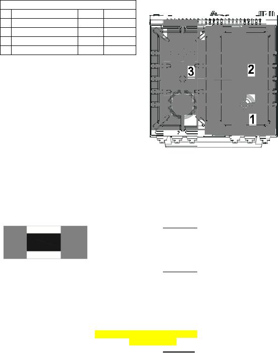
|
COOKTOP |
|
|
|
|
BTU/ hr Ratings |
|
|
|
|
|
20 |
24” |
|
1 |
Aux iliary |
2500 |
2500 |
|
2 |
Right Semi-rapid |
4300 |
4300 |
|
3 |
Left Semi-rapid |
4300 |
4300 |
|
4 |
Ra id |
8000 |
8000 |
|
Note: |
|
|
|
|
-The electric gas-ligh ting device is incorporat ed |
|
|||
into the knobs. |
|
|
|
|
CAUTION: |
|
|
|
|
If the bu rner is accidentally ext inguished, |
|
|||
turn the gas off at the control k nob and wa it |
|
|||
at least 1 minute be fore attemp ting to |
4 |
|||
relight. |
|
|
||
CAUTION: |
|
|
|
|
Gas app liances produce heat a nd humidity |
|
|||
in the e nvironment in which they are |
|
|||
installe . |
|
|
|
|
Ensure that the coo king area i s well |
|
Not : |
||
ventilat d following national/local codes. |
Line drawing above may vary from your actual unit. |
|||
Digital Kitchen Timer
|
|
|
|
When you first plug in t |
he range or |
power has returned after 10 |
|||||
|
|
|
|
hours you w ill see 12:00 in the dis play and hear an alarm tone. |
|||||||
|
|
|
|
Clock: |
|
|
|
|
|||
|
|
|
|
To set |
the clock, press SET button once, the h our position will |
||||||
|
|
|
|
flash. Adjust the hour b y pressing the up or d own button, when |
|||||||
|
|
|
|
done press SET and re peat the steps for the m inutes. To confirm |
|||||||
|
|
|
|
the setting imply wait approximately 5 seconds and the set time |
|||||||
|
|
|
|
will show in the LED di splay. |
|||||||
|
|
|
|
Cook Timer : |
|
|
|
|
|
||
|
|
|
|
Press and hold the SET button for approximately 3 seconds. The |
|||||||
|
Digital Display |
|
|
display will show 00:00. Press the up or down buttons to choose |
|||||||
|
Up (+) Button |
|
|
||||||||
|
|
|
the desired cook-time (1 – 99 minutes, default is 0 minutes). After 5 |
||||||||
|
Down (-) Button |
|
|
||||||||
|
|
|
seconds, the setting will be confir med and the countdow n will |
||||||||
|
Set Button |
|
|
||||||||
|
Back L ight ON/OFF Button |
|
|
begin. |
|||||||
|
|
|
|
The display will return o the CLOC K display, to see the countdown |
|||||||
|
|
|
|
press the S ET button 3 times. |
|||||||
|
|
|
|
Once the selected time |
has elapse |
d, the alarm will sound 15 times |
|
||||
|
|
|
|
or until a bu |
tton is pressed. |
|
|
|
|||
|
|
|
|
Backlight: ( |
Knob indic |
ator lights) |
|
||||
|
|
|
|
To turn the indicator lig |
hts behind the control panel knobs ON or |
||||||
|
|
|
|
OFF simply press the B ACKLIGHT button. |
|||||||
|
|
|
|
|
|
|
|
|
|
|
|
8

B EFOR E USING YOUR GAS RANGE
WARNING!!
HAVE THIS RANGE IN STALLED BY A QUALIF IED INSTA LLER.
Improper in stallation, a djustment, alteration, services, or maintenance can caus e injury or property damage. C onsult a qu alified insta ller, servic e agency, o r the gas supplier.
Before Using Yo ur Gas Range
√Remove the exterior and interior packing.
√Remove the protective film on steel and aluminum parts √Check to be sure you ha ve all of the parts listed below
●1 Backspl sh
●LP Gas C onversion Pa cket(injectors for LP gas , 6pcs)
●1 Anti-tip b racket
●2 Pan supports
●2 Oven ra cks
●4 Caps and bases in t e burner assembly
●1 Broiler G rid
●1 Broiler Tray
●1 Regulato r(Pre-installed)
●5 Screws for Backsplash
●1 Instructi on Manual
●1 Installation Manual
●1 Turnspit Kit(DGR24 P3S -ONLY)
√Clean the interior surface with lukewa rm water using a soft cloth
√ Have the installer show you the location of the ra |
ge’s gas shut-off valve |
nd how to shut it |
||
off if necessary. |
|
and properly grounded by a qualified installer in accordance with |
||
√ Have your range installe |
||||
the nstallation in structions. |
|
|
|
|
√ Do not attempt to repair |
r replace an y part of yo |
r range unl ss it is specifically |
||
reco mmended i |
this manual. |
|
r installer for the |
|
√ Be sure your range is cor rectly adjusted by a qua ified service technician |
||||
type of gas (nat |
ral or LP) th at is being used. |
|
|
|
√ Do not remo ve permane |
tly affixed la bels, warnin gs, or plates from the product. This may |
|||
void the warranty. |
|
|
|
|
√ The installer should leav |
these instr uctions with the consume r who should retain for l ocal |
|||
inspector’s use |
and for futur e reference. |
|
|
|
√ Please obse ve all local |
nd national codes and |
ordinances. |
|
|
9
 Loading...