

Avalon RF OTX627 User's Manual & Operating Manual
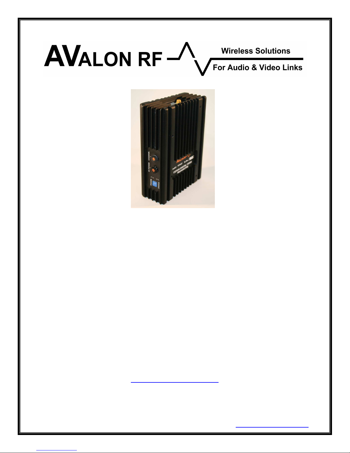
OTX627
COFDM Digital Video Transmitter
User's Guide & Operating Manual
REV. A – 14 Jan 2009
Avalon RF, Inc. • 344 Coogan Way • El Cajon, CA 92020
Phone: (619) 401-1969 • Fax: (619) 401-1971 • Email: sales@avalonrf.com
http://www.avalonrf.com/

AVALON RF, INC. Page ii
OTX627 Series User’s Guide & Operating Manual

AVALON RF, INC. Page iii
OTX627 Series User’s Guide & Operating Manual
Table of Contents
1. General................................................................................................1
Figure A – OTX Series Controls and Connectors.................................3
Video...................................................................................................4
Audio...................................................................................................4
Meta Data............................................................................................4
Talk Back Audio Channel (Optional)....................................................4
Two Way Digital Data Link (DDL) (Optional)........................................4
RF Outputs..........................................................................................4
2. Specifications & Interfaces...................................................................5
RF Specifications..........................................................................5
Video Specifications .....................................................................5
Audio Specifications .....................................................................5
Meta Data (Telemetry/User Data) (Option)...................................6
Control Interface...........................................................................6
Power...........................................................................................6
Connector/ Interface.....................................................................6
Physical........................................................................................6
User Interface......................................................................................7
Setup...................................................................................................7
Electrical Interface...............................................................................7
Table 2 – Current Consumption...........................................................8
Interconnecting..................................................................................10
Figure C – Power...............................................................................10
Figure D – Video................................................................................10
Figure E – Audio................................................................................11
Figure F – Data/Programming Input...................................................11
Mounting............................................................................................12
Mechanical Data................................................................................12
Figure G – OTX Series Mechanical Outline.......................................13
Environmental Conditions..................................................................14
3. Operating the transmitter. ..................................................................15
Operater Controls & Indicators...........................................................15
General Guidelines............................................................................17
Table 4 – Minimum Safe Distance.....................................................18
Warranty............................................................................................19

AVALON RF, INC. Page 1
OTX627 Series User’s Guide & Operating Manual
1. General
The OTX series rugged transmitters are intended for use in military,
homeland security, mobile security, broadcast and motion picture
production.
The OTX Series is a digital video transmitter using COFDM for robust
wireless video. The unit has 16 channels within a frequency range of
2.4GHz-2.483GHz and an optional extended range of 2.05GHz-
2.5GHz (for defense or licensed users only).
The transmitter carries video, stereo audio & data over the wireless
link. The data channel can be used for telemetry in UAV applications.
Some models have dual video inputs that can be used conveniently
with standard & night vision cameras. This is particularly useful for
robotic & UAV applications.
All transmitters offer the following features:
• A single broadcast quality video channel.
• Stereo audio.
• Meta-data @ 38.4kbps
• 4 power levels
Optional features (each ordered individually).
• Two-way UHF Wireless Data Link (WDL) to a ODX series receiver.
• Talk back audio channel.
AVALON RF, INC. Page 2
OTX627 Series User’s Guide & Operating Manual
1
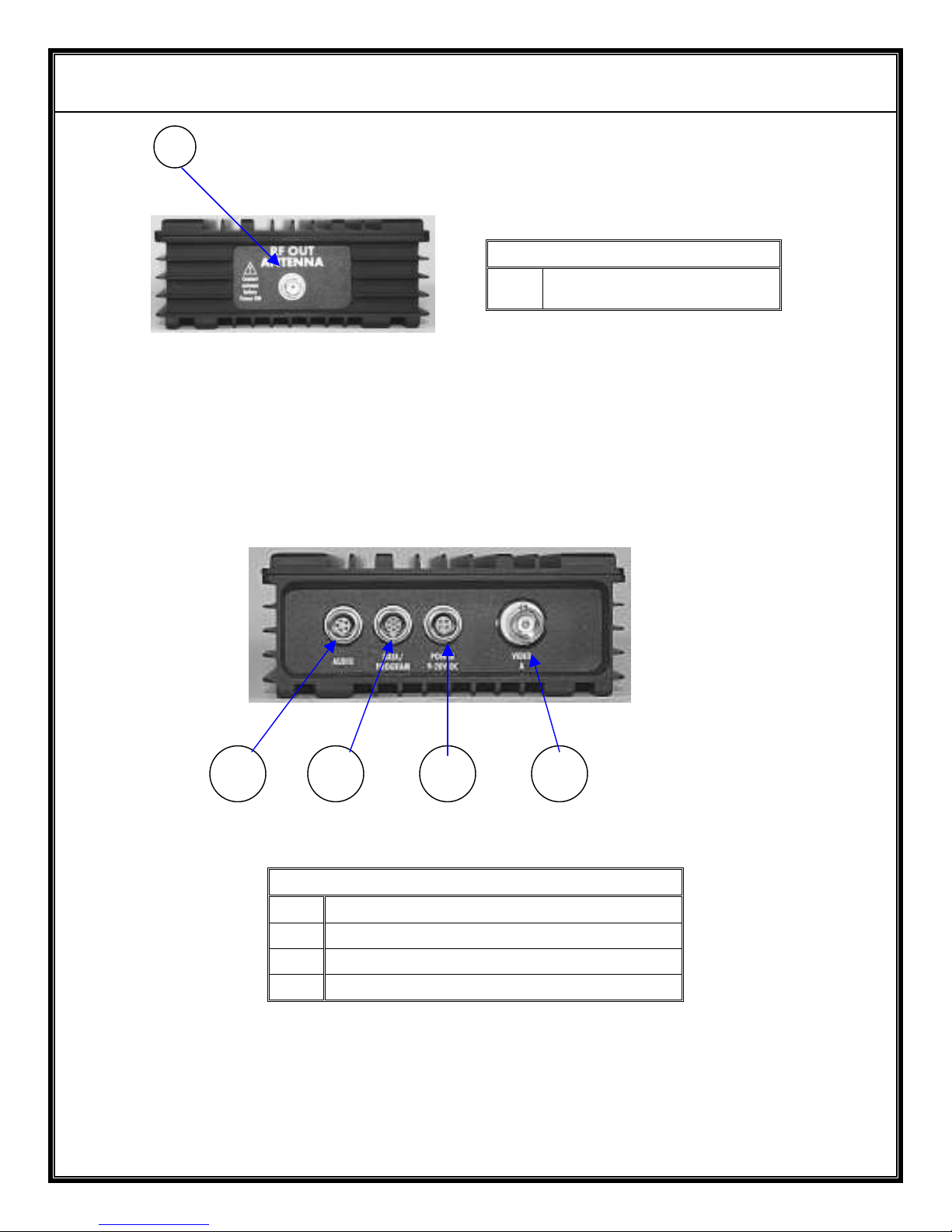
1 Main Antenna
Top View
5 3 2 4
2 Power/Video Input – see Figure C
3 Data Input – see Figures F
4 Video Input – see Figure D
5 Audio Input – see Figure E
Bottom View
Figure A – OTX Series Controls and Connectors
AVALON RF, INC. Page 3
OTX627 Series User’s Guide & Operating Manual
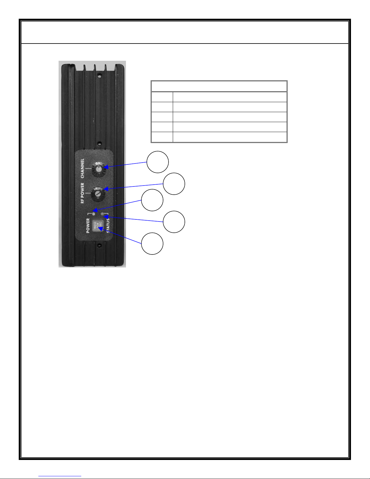
6 Power Switch
7 Power LED Indicator
8 Status Indicator
9 RF Power Switch
10 Channel Select Switch
Side Views
10
9
7
8
6
Figure A – OTX Series Controls and Connectors (contd)

AVALON RF, INC. Page 4
OTX627 Series User’s Guide & Operating Manual
1.1 Video.
Depending on the model, the unit features either 1 or 2 video inputs.
The video inputs are standard 75 ohm impedance and accept
composite video with negative sync tips.
In case of dual video inputs, the switchover between Video A & Video
B can be made via a serial mode command.
1.2 Audio.
The audio interface is stereo. Both left & right channels are balanced
line level inputs. The input impedance is high – 100K.
1.3 Meta Data.
The transmitter also carries digital meta data with the video. The
standard baud rate is 38.4K with a 8N1 format.
1.4 Talk Back Audio Channel (optional).
The talk back audio channel allows the transmit side (e.g camera
operator on the transmit side) to receive instructions from the
operator at the receiver’s side. It drives an earpiece or the output can
be used with a PA system.
1.4 Two Way Wireless Digital Link (WDL) (optional).
The WDL serves as a Pan-Tilt-Zoom (PTZ) / general-purpose twoway RS422/RS485 digital link.
1.5 RF Outputs.
The transmitters have two RF outputs (Only 1 for a standard unit,
without WDL or Talk Back Audio Option). A female SMA connector
for the main transmitter and a BNC for the WDL.
Both outputs feed antennas, either directly or through a cable.
 Loading...