

Page 1
GS-S/ GS-L
S-Band/ L-Band Ground Station
for UAV/ UGV/ USV
User's Guide & Operating Manual
REV. X0 - 21 April 2007
http://www.avalonrf.com/
Avalon RF, Inc. • 344 Coogan Way • El Cajon, CA 92020
Phone: (619) 401-1967 • Fax: (619) 401-1971 • Email: [email protected]
Page 2

AVALON RF, INC. Page ii
GS Series User’s Guide & Operating Manual
Table of Contents
1. General................................................................................................1
Figure A – GS-S-20 Controls and Connectors .....................................3
Radio Reception..................................................................................4
Video Output........................................................................................4
Telemetry Downlink (optional)..............................................................4
Control Uplink (optional) ......................................................................4
Power..................................................................................................4
2. Specifications.......................................................................................5
Electrical Specifications.......................................................................5
Interconnecting....................................................................................7
Figure B – IO Connector pinout ...........................................................7
Mounting..............................................................................................8
Mechanical Data..................................................................................9
Environmental Conditions..................................................................10
3. Operating the GS-S. ..........................................................................11
General Guidelines............................................................................11
4. Error Conditions.................................................................................12
5. Ordering information..........................................................................13
Base models......................................................................................13
Options..............................................................................................13
Recommended Accessories..............................................................14
6. Connection Diagrams.........................................................................15
Appendix A: Interface Cable diagram.................................................15
Page 3

AVALON RF, INC. Page 1
GS Series User’s Guide & Operating Manual
1. General
The Avalon RF GS series Ground Stations for Unmanned vehicles
currently has 4 modelsGS-L-13 L-Band 13 dBi receive gain
GS-L-18 L-Band 18 dBi receive gain
GS-S-15 S-Band 15 dBi receive gain
GS-S-20 S-Band 20 dBi receive gain
The GS is a complete radio Ground Station for use in military,
homeland security, mobile security etc. for reception of wireless video
from an airplane transmitter (e.g. a UAV/ Helicopter). It comprises of
a video and telemetry downlink and a UHF control uplink. The unit is
completely self-contained and requires no setup or connections of
antennas, cables etc. All accessories have been supplied to setup a
link within a few minutes.
The GS features a patented design that allows for excellent reception
of wireless video with our unique diversity mechanism. With the GSS-20 and the Avalon RF TX630 Video transmitter (higher power rf
amplifier also available) a wireless video link of more than 17-18
miles is possible. The GS does not have any moving parts, which
facilitates its usage in harsh weather including dusty/ saline/ icy
environments. It is weatherproof and all I/O including power is made
available through a robust 12-pin LEMO connector. The operating
distance depends on a variety on factors such as transmit antenna
gain, transmitter power etc.
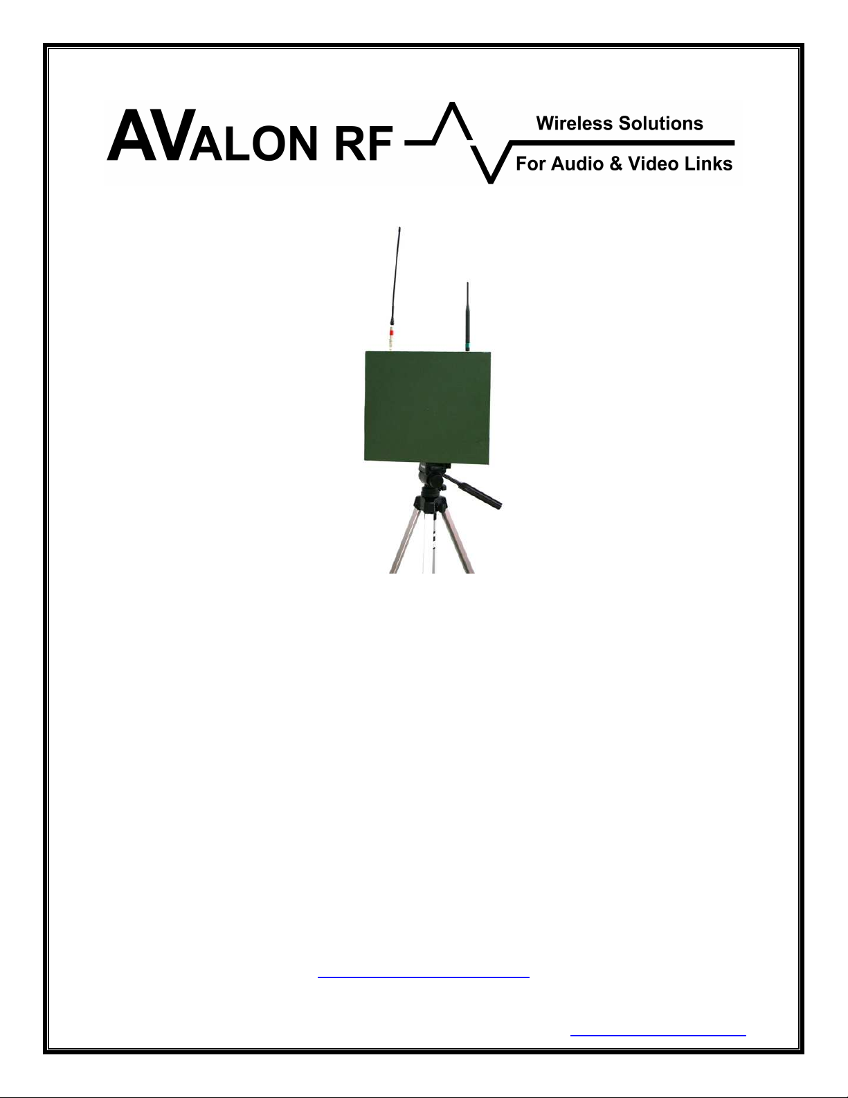
The GS-S looks like a picture frame with the front face actually a high
gain directional flat panel antenna. The diversity mechanism works
with this directional antenna and an omni directional antenna to give
the best video signal reception. The control uplink is an independent
UHF data link and has a separate antenna.
It has the following features:
• A single high quality video channel with no delay.
• Very easy setup with 16 channels for video downlink frequencies and
16 channels of UHF uplink frequencies
• RSSI signal outputs to set up a tracking system
Page 4
AVALON RF, INC. Page 2
GS Series User’s Guide & Operating Manual
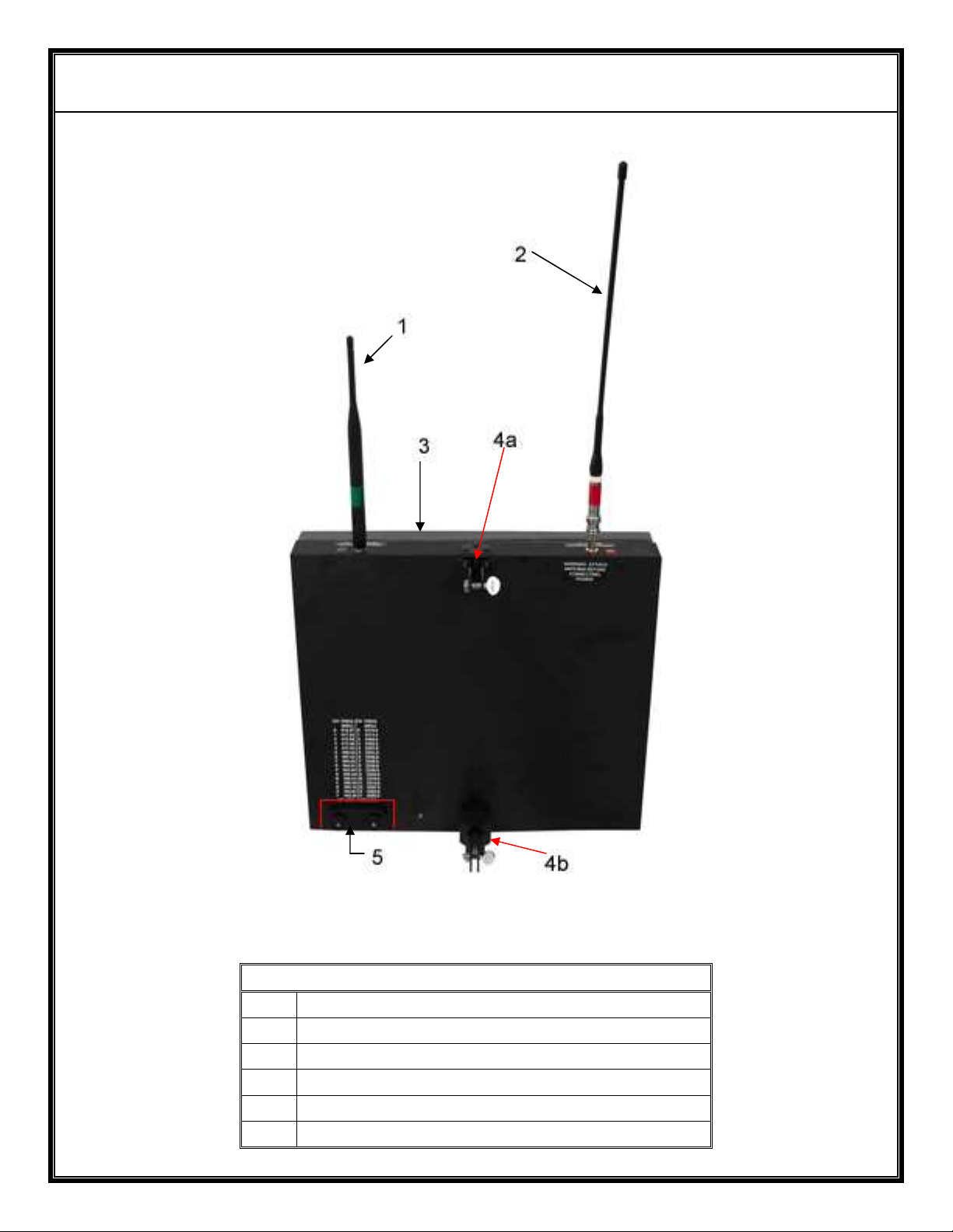
Rear View
1 Downlink Omni Antenna (Green Band)
2 Uplink Omni Antenna (Red Band)
3 High Gain Directional Flat Panel Antenna
4a Top Mounting Clamp
4b Bottom Mounting Clamp
5 Switch Cover
Page 5
AVALON RF, INC. Page 3
GS Series User’s Guide & Operating Manual
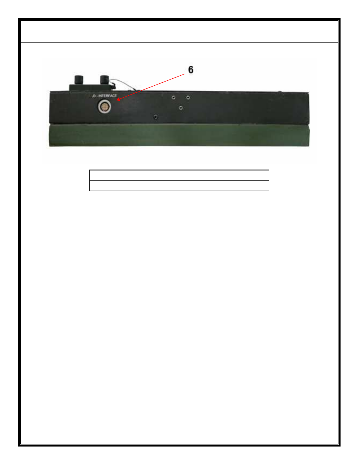
6 Interface Connector – 12 Pin LEMO
Bottom View
Figure A – GS-S-20 Controls and Connectors
Any reference to the GS-S-20 in this manual is applicable to all the
GS models except where explicitly stated.
Page 6

AVALON RF, INC. Page 4
GS Series User’s Guide & Operating Manual
1.1 RF Reception.
The GS-S-20 has a high gain 20 dBi flat panel antenna and a
detachable omni antenna (via a SMA connector) that works with our
advanced diversity electronics to yield excellent wireless video
reception. The video receiver is allowed to determine the best video
signal and the analog RSSI signals of both inputs are used to set up
a tracking mechanism.
1.2 Video Output.
The intelligent electronics in the GS-S-20 performs diversity both on
the rf signal and on the video signal. The final output is available dc
restored to ground and continuously corrected for optimum level (1V
p-p).
1.3 Telemetry Downlink.
With this feature, the audio sub-carrier on the rf signal is configured to
receive digital data at 4.8Kb/s. This received digital information is
then processed for timing recovery and made available at RS232
levels for direct connection to a serial port of a pc.
1.4 Control Uplink.
This data link is used as an uplink for camera control (typically PTZ)
and works on UHF frequencies. A separate (detachable) omni
directional antenna is installed on the GS-S-20 for communication
with a companion receiver on the airplane. The input data is RS232
compatible at 4.8Kb/s and is transmitted wirelessly with error
correction for accurate reception.
The combination of this uplink and the telemetry downlink gives a full
duplex data communication with the bird (UAV/ Helicopter).
1.5 Power.
The GS-S-20 works off a standard 12V power source. The load is
approx 1.2A or less. Please ensure that the power supply is capable
of at least 4-5A current output to allow for the turn-on current surge.
Page 7

AVALON RF, INC. Page 5
GS Series User’s Guide & Operating Manual
2. Specifications
2.1 Electrical Specifications.
Frequency Range:
GS-S 2300 – 2500 MHz (standard)
GS-L 1700 – 1850 MHz (standard)
Tuning: 16 channels (determined by user defined
frequencies) via rotary switch
RF Sensitivity: typ better than - 84 dBm
Bandwidth: 16 MHz
Antennas: 1 x 5 dBi omni antenna (detachable)
GS-S-20 1 x 20 dBi flat panel (HBW= 15; VBW= 16) on front
face
GS-S-15 1 x 15 dBi flat panel (HBW= 20; VBW= 33) on front
face
GS-L-18 1 x 18 dBi flat panel (HBW= 20; VBW= 20) on front
face
GS-L-13 1 x 13 dBi flat panel (HBW= 30; VBW= 30) on front
face
Video Output: NTSC or PAL (depending on system ordered)
Video level: 1 Vp-p into 75 ohm, Negative Sync Tip, dc restored
to ground.
Telemetry Downlink (optional)
Telemetry output: RS232 compatible signal levels with 8 data bits, No
Parity, 1 stop bit
Baud Rate: 4800 Baud
Page 8
AVALON RF, INC. Page 6
GS Series User’s Guide & Operating Manual
Control Uplink (optional)
Frequency Range: 392-420 MHz standard; any 40 MHz band in the
frequency range 350 MHz – 800 MHz possible
No of Channels: 16 via rotary switch (user determined channel
frequencies)
RF Impedance: 50 ohm
RF Output: 1W
Antenna: Half wave Omni directional (2.2 dBi gain),
detachable
Data Input: RS232 compatible signal with 8 data bits, No Parity,
1 stop bit
Data Rate: 4800 Baud
Power: 12V unregulated DC nominal; 10 -17V DC input
Consumption: < 1.3A
Page 9
AVALON RF, INC. Page 7
GS Series User’s Guide & Operating Manual
2.2 Interconnecting.
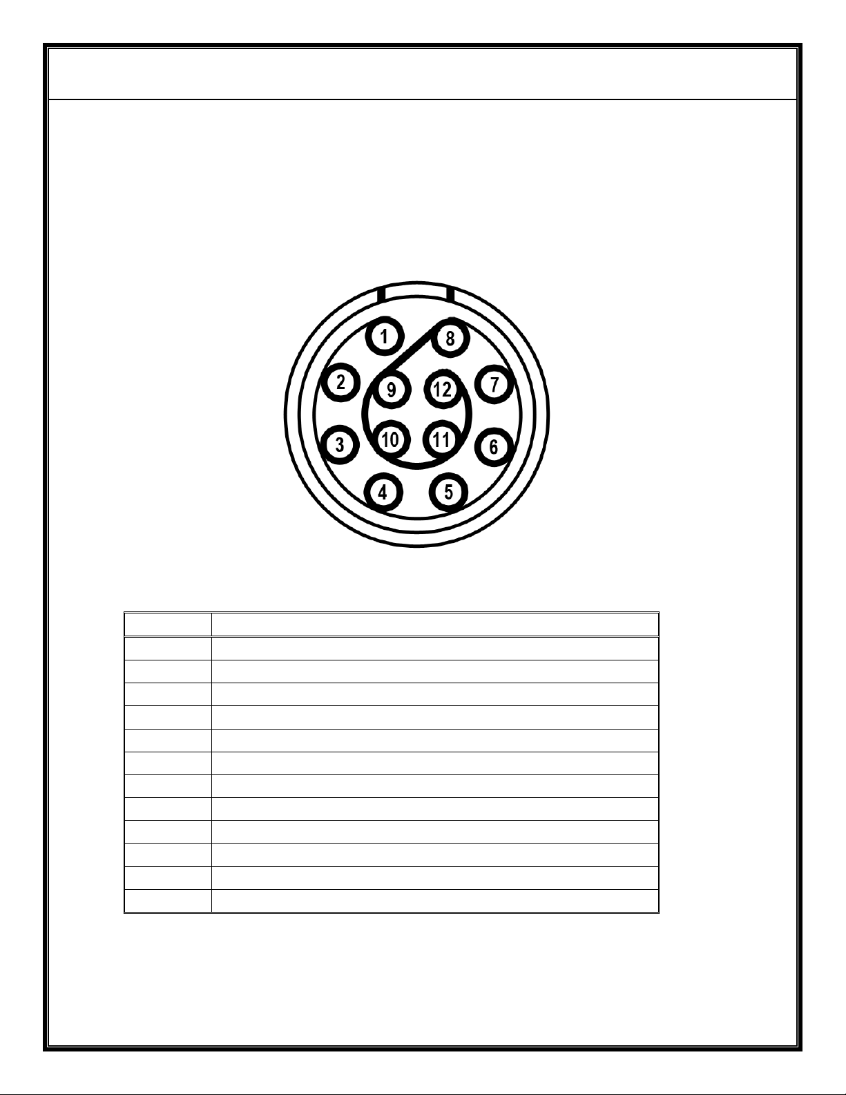
All input/ output signal connections to the GS-S-20 are available
through the 12-pin connector on the bottom of the unit.
The pin out of the 12-pin connector is as shown in figure B.
Figure B – IO Connector pinout
Pin # Function
1 Power Input (10 Vdc to 17Vdc)
2 Power Return
3 Video Output
4 Video Return/ground
5 RSSI- Antenna 1
6 RSSI- Antenna 2
7 Program Tx (RS232)
8 Program Rx (RS232)
9 Signal ground
10 Uplink Enable
11 Downlink/ Telemetry data (RS232 level)
12 Control / Uplink data (RS232 level)
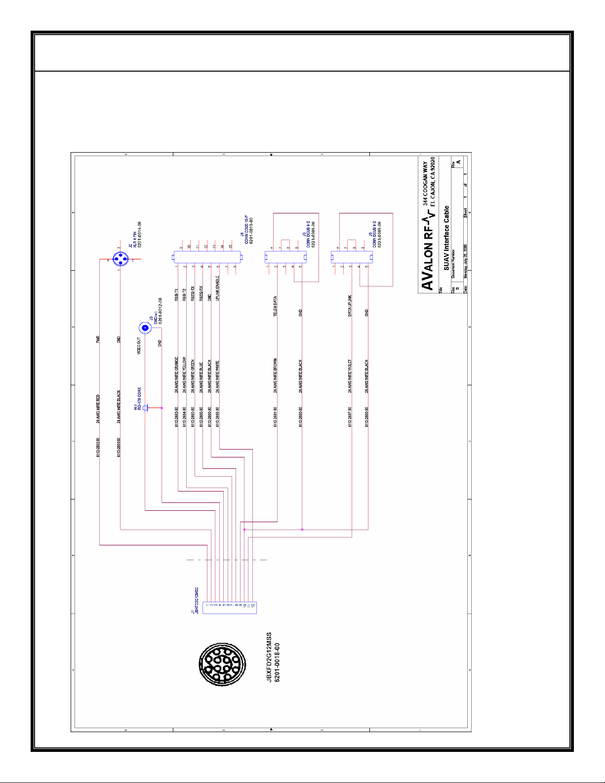
Avalon RF has supplied a 12-pin cable that breaks out into separate
connections for power, video, telemetry and control uplink data. The RSSI
signals and the programming RS232 signals are also brought out on this
cable.
Page 10

AVALON RF, INC. Page 8
GS Series User’s Guide & Operating Manual
2.5 Mechanical
2.5.1 Mounting/ Installation.
The GS-S-20 is light enough to be carried in a backpack. The
mounting brackets have been designed to tilt the antenna correctly
for a target UAV at a distance of about 5miles or more and flying at
an altitude of > 500 ft. It is designed to be mounted to a pole with a
tripod mount. The user can use other mounting methods to suit their
specific applications.
As a general rule, the GS-S-20 should be placed as high as is
practically possible to maximize the operating range/ distance. The
GS-S-20 should be mounted/ installed with the 2 detachable
antennas upright. Also, ensure that there is a clear radio line-of-sight
between the UAV/ transmitter and the GS-S-20 and that there are no
high power transmitters in close proximity (even though they maybe
known to be on other frequencies/ frequency bands.
As with any portable equipment, please exercise care and ensure
safety of personnel. Do not place the unit at a location where if
accidentally knocked over, it might jeopardize the safety of others.
Page 11
AVALON RF, INC. Page 9
GS Series User’s Guide & Operating Manual
2.5.2 Mechanical Data.
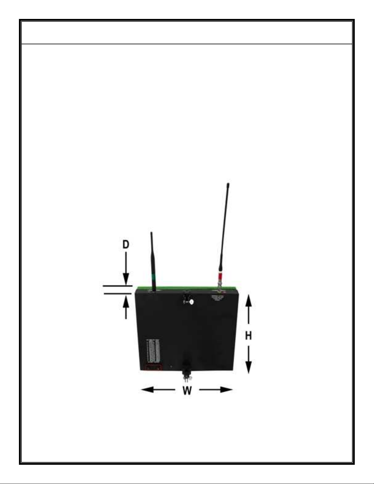
a) Size (see Figure G) W (in/mm) x H (in/mm) x D (in/mm)
GS-S-20 13.5/ 343 x 12/ 305 x 3.5/ 89
GS-S-15 10.5/ 267 x 6.5/ 165 x 3/ 76
GS-L-18 15.5/ 394 x 16/ 406 x 3.5/ 89
GS-L-13 9.5/ 241 x 9.5/ 241 x 3/ 76
b) Weight < 2.7 lbs (1.2 Kgs) without interface cable
c) Shipping weight < 5.5 lbs (2.5 Kgs)
Figure G – GS Series Mechanical Outline
Page 12

AVALON RF, INC. Page 10
GS Series User’s Guide & Operating Manual
2.6 Environmental Conditions.
The TA-8 Series is designed to meet the following environmental
conditions:
2.6.1 Operating temperature -4° to 122° F
-20° to 50° C
2.6.2 Storage temperature -13° to 150° F
-25° to 65° C
2.6.3 Humidity 5 to 95%, non-condensing
2.6.4 Inclination Any
2.6.5 Altitude -1500 feet to 15,000 feet
-450 meter to 4,500 meters
Page 13

AVALON RF, INC. Page 11
GS Series User’s Guide & Operating Manual
3. Operating the GS-S.
All required internal antenna connections have been made inside the
GS-S. If installing any user equipment inside the enclosure, please do
not disconnect any factory made antenna connections.
NOTE
The GS-S requires a radio line of sight (LOS) to work correctly. It
may be used in other partially blocked LOS situations but the
operating distance could be significantly reduced.
WARNING
The Uplink antenna MUST be connected before powering on the
GS-S. Failure to do so might damage the Uplink power amplifier.
Operation of the GS-S is very simple. The user must first connect the
2 detachable omni antennas – the Uplink antenna and the downlink
antenna. Mount the GS-S on a stable tripod or base.
Unscrew the frequency select switch cover (it is anchored by a wire to
the frame) and let it hang loose. Do not remove the cover completely
by cutting the holding wire or unscrewing its retainer. This cover has
a water tight seal and is essential to protect the electronics inside
from ingress of water. Select the downlink frequency of the signal of
interest and the control Uplink frequency to match the UAV/ vehicle
(the frequencies selection can also be done later).
Connect the interface cable connectors to the respective receptacles/
plugs and then plug into the GS-S.
3.1 General Guidelines
While the setup of the GS-S link is very simple, observing a few
considerations will help get the optimum performance.
First, height of the equipment plays an important role in the distance
over which the radio link works. The higher you place the GS-S, the
longer the available link range. This is a direct result of the increased
distance to horizon and clearing/ improving any Fresnel zone
Page 14

AVALON RF, INC. Page 12
GS Series User’s Guide & Operating Manual
obstacles. Please use proper judgment of safety when following this
advice, especially for mobile applications.
For any rf signal, having metal objects near the receiving or
transmitting antenna will severely affect the performance. With this in
mind, avoid placement in any location that has large metal structures
or objects that hinder a good LOS to the transmitter. The GS-S being
a microwave receiver, trees and buildings are also an obstruction to
signal reception.
The radio link must be configured correctly and the equipment
chosen to meet the required range/ distance. Choice of transmitter
amplifier, output power, type of antenna etc. is governed by
considerations such as battery power on the UAV/ airplane,
permissible antenna height on the UAV/airplane, cooling for
transmitter etc. If you need assistance, please call Avalon RF
Engineering at 619-401-1967.
4. Error Conditions
T.B.D.
Page 15

AVALON RF, INC. Page 13
GS Series User’s Guide & Operating Manual
5. Ordering information
5.1 Base models
GS-S-20 S-band 20 dBi Ground Station
GS-S-15 S-band 15 dBi Ground Station
GS-L-18 L-band 18 dBi Ground Station
GS-L-13 L-band 13 dBi Ground Station
All units come with the following standard accessories:
5.1.1 Universal input (100 – 240V, 50-60 Hz) AC power adaptor.
5.1.2 User guide & operating manual (this manual).
5.1.3 Interface cable for connection of data IO.
5.2 Options.
5.2.1 Option 00 – European version (PAL).
Page 16

AVALON RF, INC. Page 14
GS Series User’s Guide & Operating Manual
5.3 Recommended accessories.
5.3.1 Additional power (power/ data IO) cable for mobile applications
Page 17
AVALON RF, INC. Page 15
GS Series User’s Guide & Operating Manual
6. Connection Diagrams
Appendix A
Interface Cable Diagram
 Loading...