

Page 1
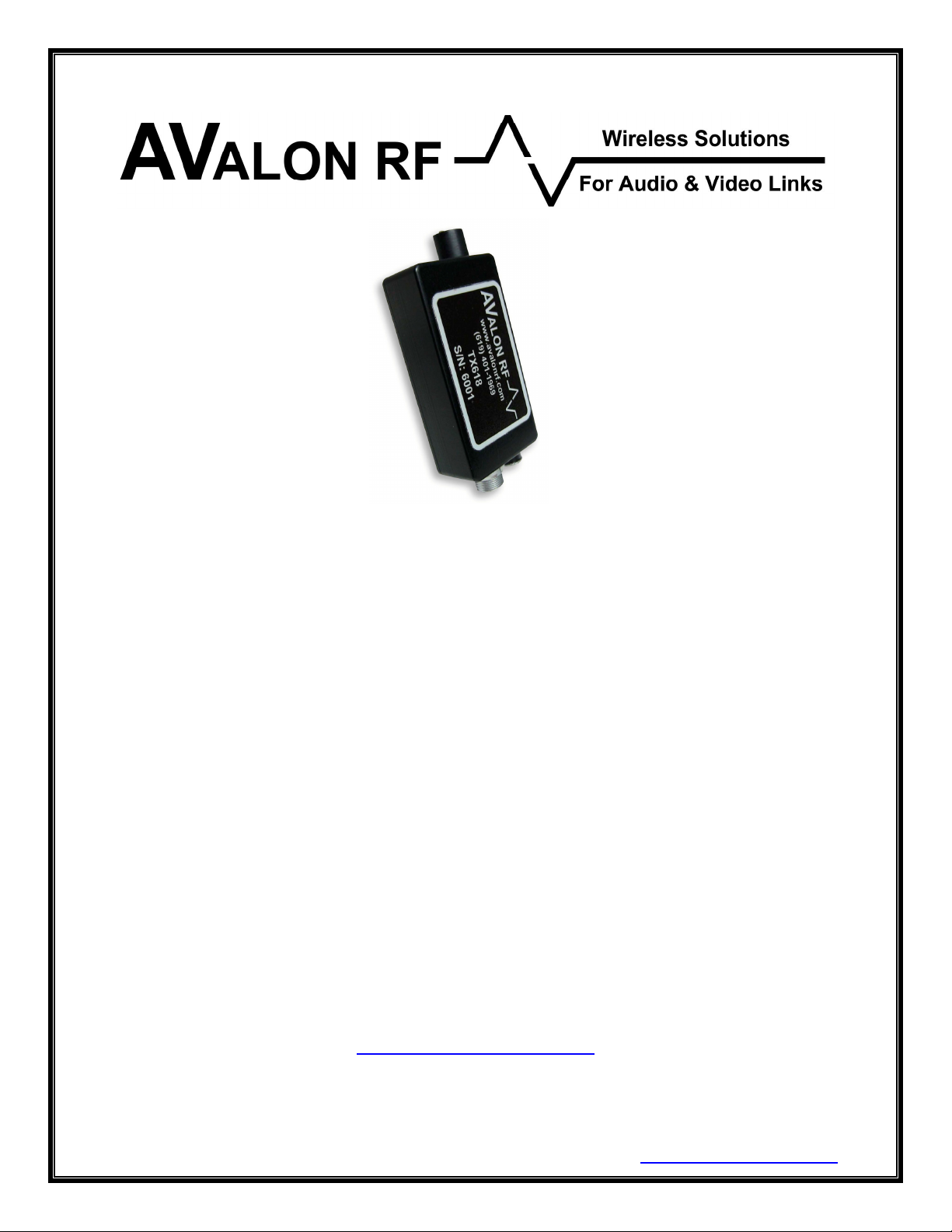
TX418M - UHF
TX518M - 900MHz-2.15GHz
TX618M - 2.15GHz-2.5GHz
70 mW Video Transmitter
User's Guide & Operating Manual
AV030528/1-000
REV. A1 - 23 December 2003
Prepared by Steve Jones
Authored by Eli Weinstein
http://www.avalonrf.com/
Avalon RF, Inc. • 344 Coogan Way • El Cajon, CA 92020
Phone: (619) 401-1969 • Fax: (619) 401-1971 • Email: [email protected]
Page 2

AVALON RF, INC. Page ii
TX418M/TX518M/TX618M User’s Guide & Operating Manual
Table of Contents
1. General .................................................................................................1
Figure A – TX618M Series Controls and Connectors ...........................2
Video.....................................................................................................3
Audio.....................................................................................................3
RF Output .............................................................................................3
2. Specifications ........................................................................................ 4
User Interface .......................................................................................4
Setup ....................................................................................................4
Electrical Interface ................................................................................4
Interconnecting .....................................................................................5
Figure B – Power/Video ........................................................................ 5
Figure C – Audio/Video.........................................................................5
Mechanical............................................................................................6
Mounting ...........................................................................................6
Mechanical Data................................................................................7
Figure D – TX618M Mechanical Outline ............................................... 7
Environmental Conditions ..................................................................... 8
3. Operating the transmitter. .....................................................................9
Operator Controls & Indicators .............................................................9
Channel Select..................................................................................9
On/Off................................................................................................9
4. Ordering information ...........................................................................10
Base models .......................................................................................10
Options ...............................................................................................11
Recommended Accessories ...............................................................12
Antennas .........................................................................................12
Cables .............................................................................................12
Battery Packs ..................................................................................12
Page 3

AVALON RF, INC. Page 1
TX418M/TX518M/TX618M User’s Guide & Operating Manual
1. General
The TX418M/TX518M/TX618M series rugged transmitters are
intended for use in short range military, homeland security, mobile
security, broadcasting and motion picture production. All have an RF
output power of approx. 70mW.
The following table details a brief matrix of the transmitters:
Model Tuning range
TX418M 460MHz-860MHz 460MHz-860MHz VSB
TX518M 900MHz-926MHz 900MHz-2.150GHz FM
TX618M 2.4GHz-2.48GHz 2.150GHz-2.5GHz FM
All transmitters offer the following features:
• A single broadcast quality video channel with no delay.
• Two broadcast quality audio channels.
Any reference in this manual to TX618M series also implies the
TX418M and TX518M.
Extended tuning
Modulation
range (optional)
Page 4
AVALON RF, INC. Page 2
TX418M/TX518M/TX618M User’s Guide & Operating Manual
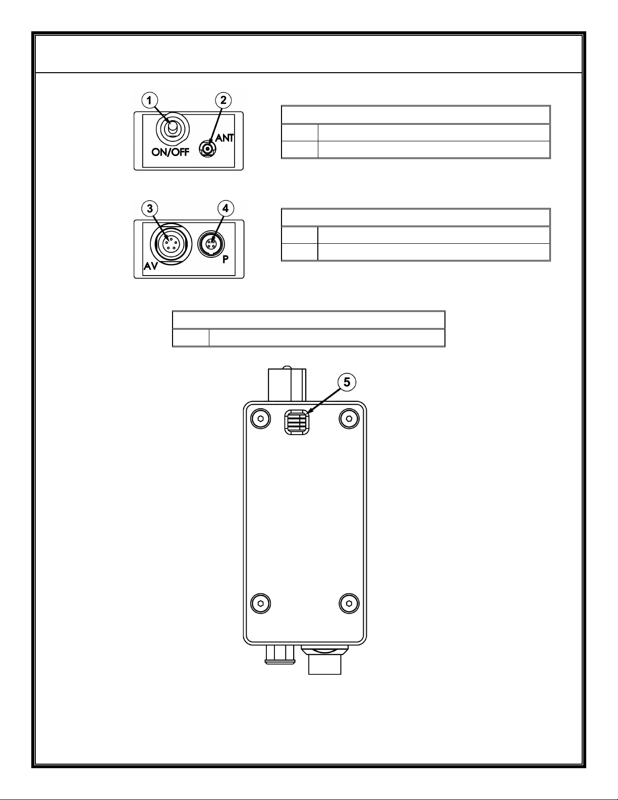
Top View
1 Power On/Off
2 Antenna - MMCX
Bottom View
3 Audio/Video Input – See Figure C
4 Power/Video Input – See Figures B
Back View
5 Frequency Select
Figure A – TX618M Series Controls and Connectors
Page 5

AVALON RF, INC. Page 3
TX418M/TX518M/TX618M User’s Guide & Operating Manual
1.1 Video.
The video input is buffered, combined with the two audio subcarriers,
then DC level restored, limited by a white level clipping circuit, preemphasized and (VSB on TX418M series) (FM onTX518M/TX618M
series) modulated onto the transmitter RF carrier.
Avalon RF offers the following video indices of modulation
(TX518M/TX618M only):
• Industry standard frequency deviation of 4MHz.
This option offers longer range at reference quality.
• Wide frequency deviation of 6MHz.
This option offers broadcast quality but with shorter range.
1.2 Audio.
The two audio inputs are buffered and FM modulated on two
subcarriers. The factory preset subcarrier frequency is 6.0MHz and
6.5MHz but may be factory programmed to any frequency from
4.8MHz to 7.5MHz.
1.3 RF Output.
The TX618M has a single MMCX RF output with a 50
impedance.
Ω (ohm)
Page 6

AVALON RF, INC. Page 4
TX418M/TX518M/TX618M User’s Guide & Operating Manual
2. Specifications
2.1 User Interface - On/Off Switch.
The TX618M series transmitter has an on/off switch. This shuts off
power to the entire transmitter.
2.2 Setup.
The TX618M transmitter has four frequency select switches that
select a frequency (1 of 16). The preset frequencies are defined by a
label on the transmitter.
The user is advised to select a channel within the permissible
frequency range to begin with, and if any interference is observed,
switch over to another channel.
The transmitter retains its setup during power down.
2.3 Electrical Interface.
The transmitter has the following interfaces:
2.3.1 Power Input
a) The transmitters operate off a 9Vdc-16Vdc unregulated voltage
source.
b) This input is switched and protected against reverse polarity.
c) Typical power input current consumption is 160mA.
2.3.2 Video Input.
a) The video input accepts RS170, CCIR, NTSC or PAL signals.
b) Input voltage is 1Vp.p with a negative sync tip of 0.3V.
c) The input impedance is 75
Ω (ohm).
Page 7
AVALON RF, INC. Page 5
TX418M/TX518M/TX618M User’s Guide & Operating Manual
2.3.3 Audio 1 and Audio 2 Inputs.
The audio inputs accept signals of 1Vp.p. and have an input
impedance of 600
2.3.4 RF output to antenna.
Ω (ohm).
a) The main RF output connector is a 50
b) The RF output power is approx. 70mW.
2.4 Interconnecting.
The interface to/from the transmitter is:
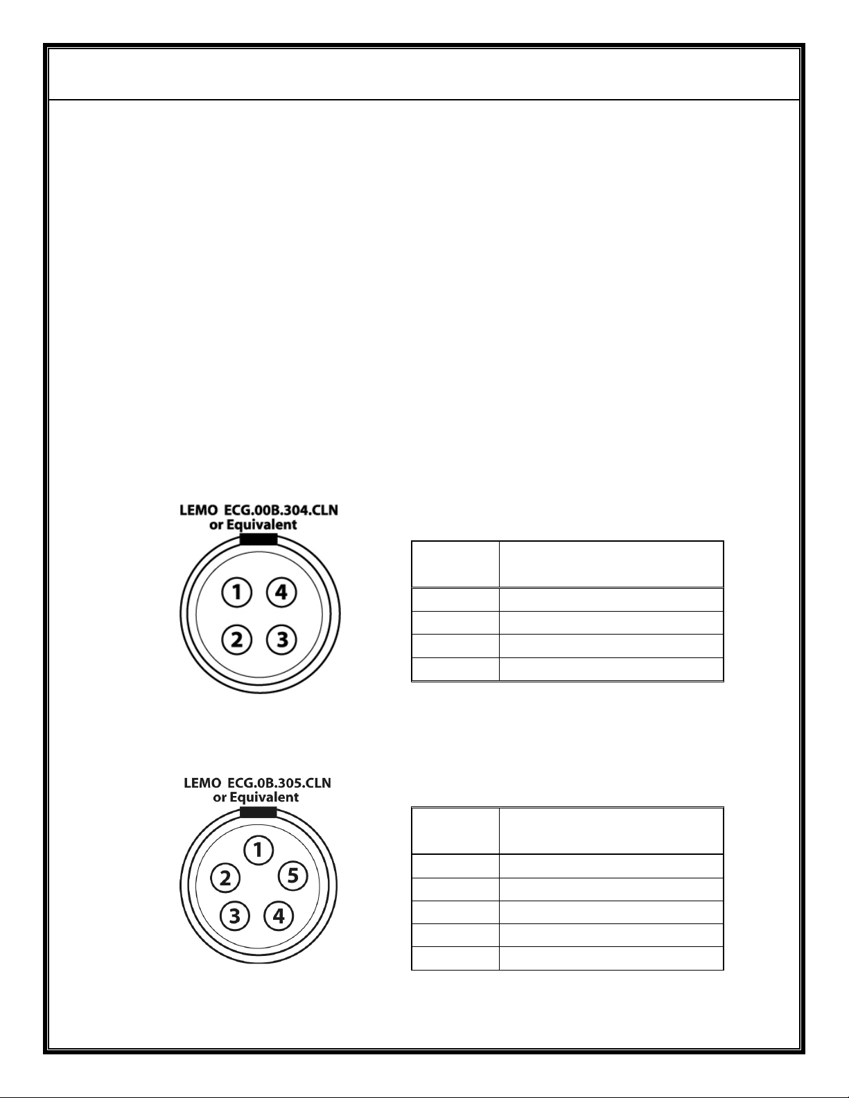
a) Power/Video Input.
Ω (ohm) MMCX receptacle.
Pin
Function
Number
1 Power Return
2 Video Input
3 Video Return
4 Power Input
Figure B – Power/Video
b) Audio/Video Input.
Figure C – Audio/Video
Pin
Function
Number
1 Audio Return
2 Audio 1 Input
3 Audio 2 Input
4 Video Input.
5 Video Return
Page 8

AVALON RF, INC. Page 6
TX418M/TX518M/TX618M User’s Guide & Operating Manual
2.5 Mechanical
2.5.1 Mounting.
Mounting can be done in one of the following methods:
a) Clamping.
Clamping (or hard mounting) is the only method of mounting in all
fixed installations.
Clamping is the preferred method of mounting in all mobile
installations where most electrical interfaces are used. This is due
to the connector and cable weight.
b) Clip on.
Avalon RF offers a clip on kit. This method is recommended when
only one or two interfaces are in use.
c) Velcro
Using Velcro
®
to a flat surface.
®
to secure the transmitter is recommended when
only a few interfaces are in use.
d) Drop-in.
The transmitter can be dropped into a bucket mounted on the side
of the video camera, like the ones usually found in ENG service.
Page 9
AVALON RF, INC. Page 7
TX418M/TX518M/TX618M User’s Guide & Operating Manual
2.5.2 Mechanical Data.
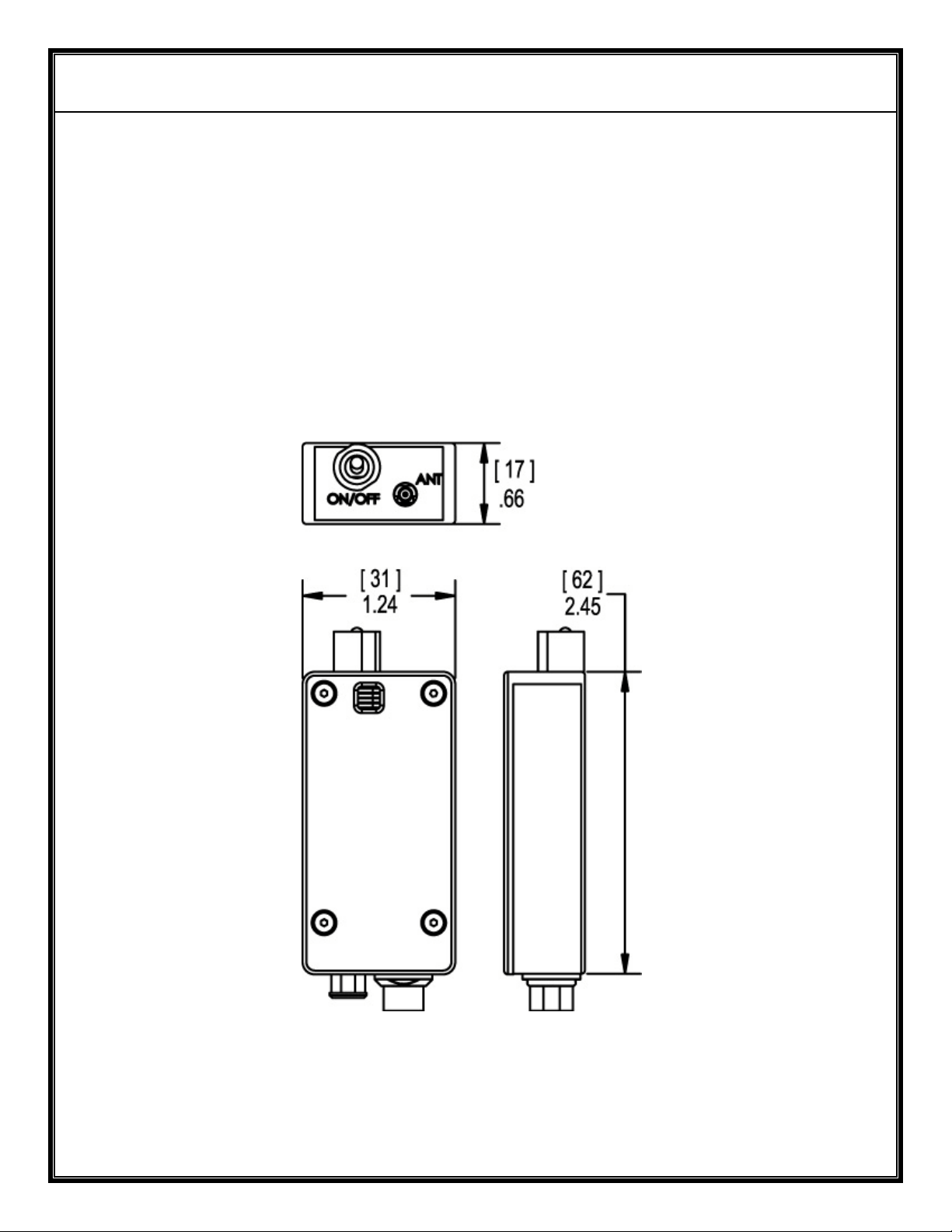
a) Size 2.45” x 1.24” x 0.66 (see Figure D)
62mm x 31mm x 17mm
b) Weight <5.6 oz.
<158 gram
c) Shipping weight <32 oz.
<900 gram
Figure D – TX618M Mechanical Outline
Page 10

AVALON RF, INC. Page 8
TX418M/TX518M/TX618M User’s Guide & Operating Manual
2.6 Environmental Conditions.
The TX618M Series is designed to meet the following environmental
conditions:
2.6.1 Operating temperature -4° to 122° F
-20° to 50° C
2.6.2 Storage temperature -13° to 150° F
-25° to 65° C
2.6.3 Vibration 1.5G, from 10Hz to 2KHz, sine wave, 3 axis
2.6.4 Shock 15G, 25msec, half sine wave, three axis
2.6.5 Humidity 5 to 95%, non-condensing
2.6.6 Inclination Any
2.6.7 Altitude -1500 feet to 15,000 feet
-450 meter to 4,500 meters
Page 11

AVALON RF, INC. Page 9
TX418M/TX518M/TX618M User’s Guide & Operating Manual
3. Operating the transmitter.
Before applying power, make sure all connectors and all antennas
are hooked up.
NOTE
The transmitter will not transmit unless it has an antenna.
3.1 The transmitter has two operator controls and one indicator:
a) Channel select.
Units that have a manual synthesizer have a 4 position dip switch
that selects a channel number (from 1 to 16). The preset channel
numbers are defined by a label on the side wall of the transmitter.
b) On/Off
Page 12

AVALON RF, INC. Page 10
TX418M/TX518M/TX618M User’s Guide & Operating Manual
4. Ordering information
4.1 Base models.
TX418M UHF VSB modulated, output power (OP) of 70mW
TX518M 900-928MHz, FM modulated, OP of 70mW
TX618M 2.4GHz-2.483GHz, FM modulated, OP of 70mW
All units come with the following standard accessories:
4.1.1 Omni directional ¼ wavelength whip antenna
4.1.2 A 3-foot power cord with flying leads to connect to a customer
specific battery pack.
4.1.3 User guide & operating manual (this manual).
4.1.4 A reusable carton.
Page 13

AVALON RF, INC. Page 11
TX418M/TX518M/TX618M User’s Guide & Operating Manual
4.2 Options.
4.2.1 Option 00 – European version (TX418M only).
Tunes from 470MHz to 860MHz with European channel spacing.
4.2.2 Option 03 – Wideband (TX518M only)
4.2.4 Option 04 – Extended tuning range
TX418M not available
TX518M 900MHz-1.3GHz
TX618M 2.150GHz to 2.5GHz
4.2.5 Option 05 – Extended tuning range (TX518M-2 only)
Tuning range from 1.3GHz to 1.7GHz
4.2.6 Option 06 – Extended tuning range (TX518M only)
Tuning range from 1.7GHz to 2.15GHz
4.2.7 Option NM – Basic unit installed in an outdoor NEMA 4 box with an
internal power and signal distribution panel.
4.2.8 Option SP – Basic unit installed in an outdoor NEMA 4 box with
solar panel, charger and internal lead-acid battery
Page 14
AVALON RF, INC. Page 12
TX418M/TX518M/TX618M User’s Guide & Operating Manual
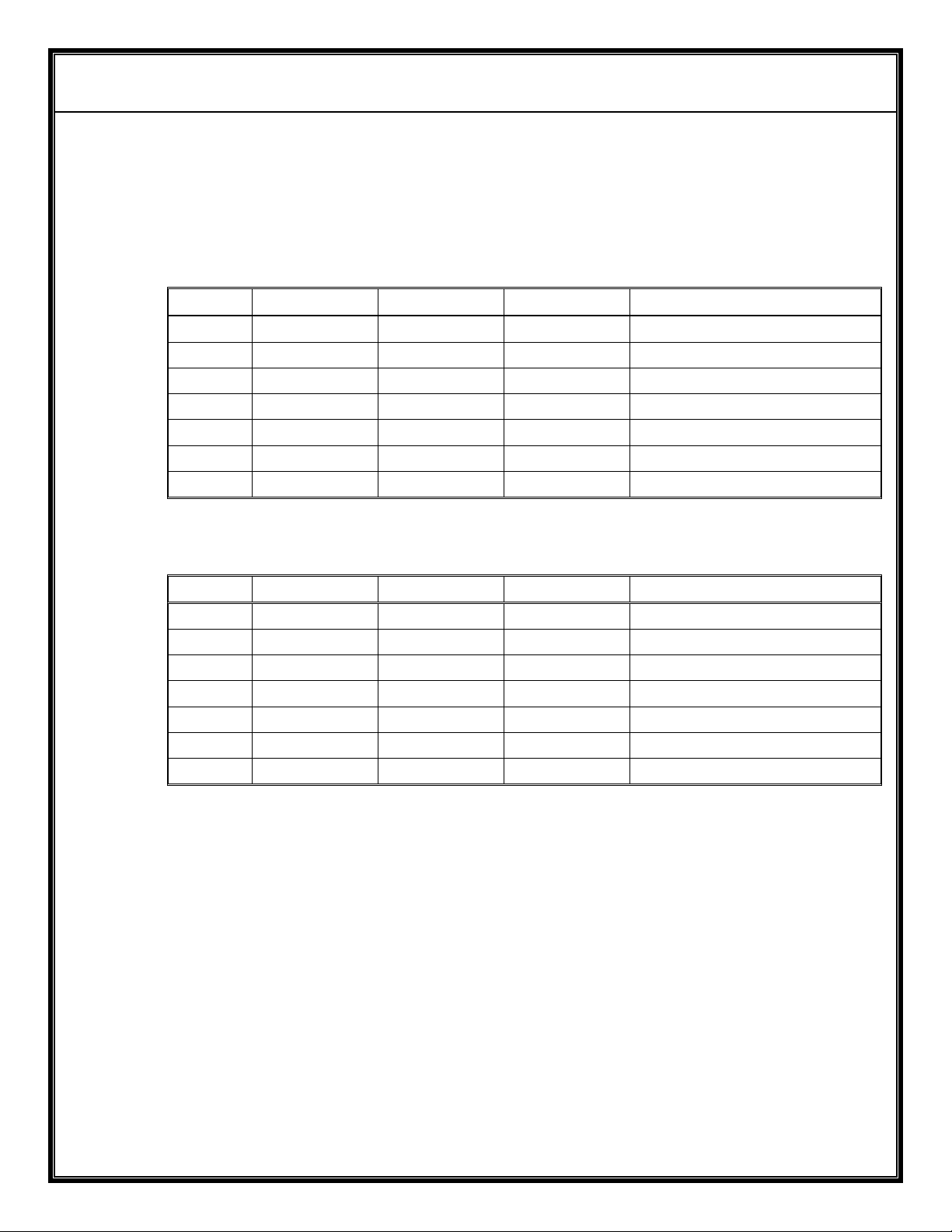
4.3 Recommended accessories.
4.3.1 Antennas
Omni-directional antennas for mobile application:
Gain UHF 900MHz 2.4GHz Comments
0dbi AX400 AX500 AX600 ¼ wave whip
3dbi AX503CP AX603CP RHCP whip
4dbi AX504LS AX504CP RHCP Log Spiral
6dbi AX406CP AX606 Vertical polarized whip
8dbi AX608 Vertical polarized whip
Directional antennas for ground fixed applications:
Gain UHF 900MHz 2.4GHz Comments
6dbi AX406LP AX506LP Log periodic
10dbi AX610CP Circular polarized panel
12dbi AX412YG AX512YG Vertical polarized whip
13dbi AX613CP Vertical polarized whip
16dbi AX616CP Vertical polarized whip
24dbi AX624PD Vertical polarized whip
27dbi AX627PD Vertical polarized whip
4.3.2 Cables
T.B.D.
4.3.3 Battery Packs
a) BAT80 – 14.4V/80WH Li-Ion battery pack with charger and power
cable to transmitter. Will run a TX618M transmitter for 20 hours.
b) BAT92 – 14.4V/92WH Li-Ion battery pack with charger and power
cable to transmitter. Will run a TX618M transmitter for 23 hours.
 Loading...