

Page 1
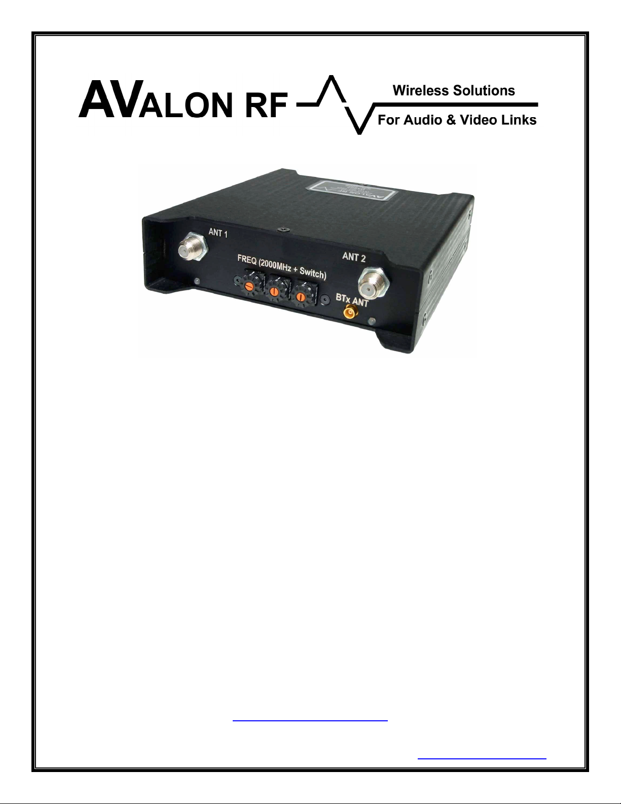
DX402 / DX502 / DX602
Two Antenna Diversity
Receivers
User's Guide & Operating Manual
AV010220/1-000
REV. A1 - 28 April 2004
Edited by Eli Weinstein
Prepared by Steve Jones
http://www.avalonrf.com/
Avalon RF, Inc. • 344 Coogan Way • El Cajon, CA 92020
Phone: (619) 401-1969 • Fax: (619) 401-1971 • Email: [email protected]
Page 2

AVALON RF, INC. Page ii
DX402/DX502/DX602 User’s Guide & Operating Manual
Table of Contents
1. General .................................................................................................1
Figure A – Front Panel (Broadcast & Security Versions) ......................2
Figure B – Rear Panel – Broadcasting.................................................. 3
Figure C – Rear Panel – Security .........................................................3
2. Specifications ........................................................................................ 4
Power Input - Broadcast Version ..........................................................4
Figure D – Power Input .....................................................................4
Antenna Inputs......................................................................................5
Video Output - Broadcast Version ........................................................5
Audio Outputs - Broadcast Version.......................................................5
Figure E – Audio Output(s)................................................................5
Digital Wireless Link Data Input - Broadcast Version ...........................6
Figure F – Digital Wireless Link Data Input .......................................6
Digital Wireless Link Antenna Output ...................................................6
Interface - Security Version...................................................................7
Figure G – Interface - Security Version ............................................. 7
Power Input - Security Version .............................................................7
Video Output - Security Version............................................................7
Audio Output - Security Version............................................................8
Audio talk back - Security Version ........................................................8
Wireless Data Link (WDL)- Security Version ........................................ 8
Digital Wireless Link Data Input - Security Version............................... 8
Telemetry Output - Security Version.....................................................8
RS232 Input - Security Version.............................................................8
Size.......................................................................................................9
Weight................................................................................................... 9
Figure H – DX602 Mechanical Specifications - Inches [mm] ..............10
Environmental Conditions ................................................................... 11
3. Operating Instructions ......................................................................... 12
Human Interface .................................................................................12
Front Panel Frequency Select Switches .........................................12
Front Panel Indicators .....................................................................12
Operating the DX602 ..........................................................................12
Tuning ............................................................................................. 12
4. Ordering Information ...........................................................................14
Optional features.............................................................................15
Optional accessories ....................................................................... 16
Page 3

AVALON RF, INC. Page iii
DX402/DX502/DX602 User’s Guide & Operating Manual
Figure I – Block Diagram – Basic System w/ Single Receiver ........18
Figure J – Block Diagram – Basic System with Four Receivers......19
Appendix A – Remote Programming Option .............................................. 20
Page 4

AVALON RF, INC. Page 1 of 20
DX402/DX502/DX602 User’s Guide & Operating Manual
1. General
The DX402/DX502/DX602 are rugged 2-antenna ‘true’ diversity video
and audio receivers intended for demanding high end video
applications.
The DX402 tuning range is from 56MHz to 802.25MHz
The DX502 tuning range is from 900 MHz to 928 MHz. (*)
The DX602 tuning range is from 2400 MHz to 2500 MHz. (**)
NOTE
Unless explicitly stated, every reference in this document to
the DX602 also implies the DX402 and DX502. The main
difference between the models is the frequency range.
The DX602 receiver has the following standard channels:
A video channel.
An audio channel.
And the following optional features:
Broadcasting industry options
• Remote synthesizing of a TX600, TX623 or TX630.
• Talk back audio channel.
• Lemo interface connectors.
Security industry options
• Remote control of the receiver via RS232.
• Remote synthesizing of a TX600, TX623 or TX630.
• Serial communication channel for Pan/Tilt/Zoom control.
• Alarm output.
• Analog telemetry outputs (three).
(*) Optional - Extended Tuning Range from 900-2150 MHz.
(**) Optional - Extended Range from 2150 to 2500 MHz.
Page 5
AVALON RF, INC. Page 2 of 20
DX402/DX502/DX602 User’s Guide & Operating Manual
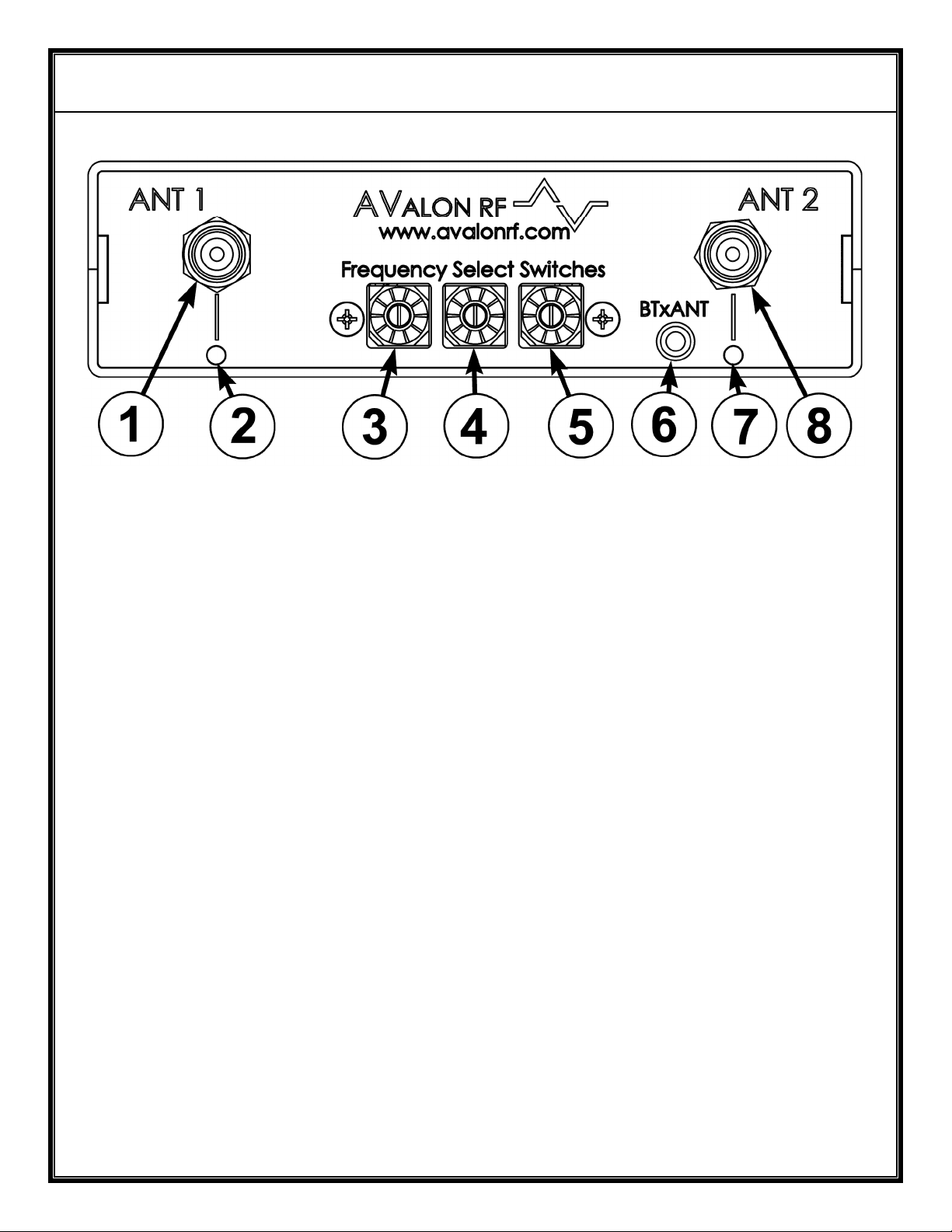
Figure A – Front Panel (Broadcast & Security Versions)
DX402/DX502/DX602 Controls, Indicators and Connectors
1 - Antenna 1 Input
2 - Antenna 1 Select LED (Light Emitting Diode)
3 - Frequency Selector Switch/EIN 1
4 - Frequency Selector Switch/EIN 2
5 - Frequency Selector Switch/EIN 3
6 - BTx (Back Channel Transmitter) Antenna
7 - Antenna 2 Select LED
8 - Antenna 2 Input
Page 6
AVALON RF, INC. Page 3 of 20
DX402/DX502/DX602 User’s Guide & Operating Manual
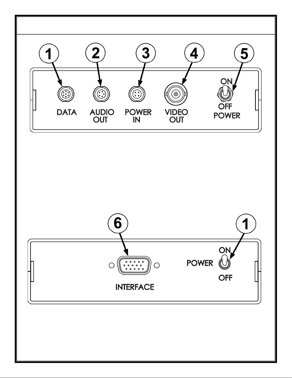
Figure B – Rear Panel – Broadcasting
DX402/DX502/DX602 Controls and Connectors
1 - Data Output (section 2.4) 4 - Video Output (section 2.6)
2 - Audio Output (section 2.5) 5 - On/Off Switch
3 - Power In (section 2.1)
Figure C – Rear Panel – Security
DX402/DX502/DX602 Controls and Connectors
1 - On/Off Switch 6 - Interface (section 2.7)
Page 7
AVALON RF, INC. Page 4 of 20
DX402/DX502/DX602 User’s Guide & Operating Manual
2. Specifications
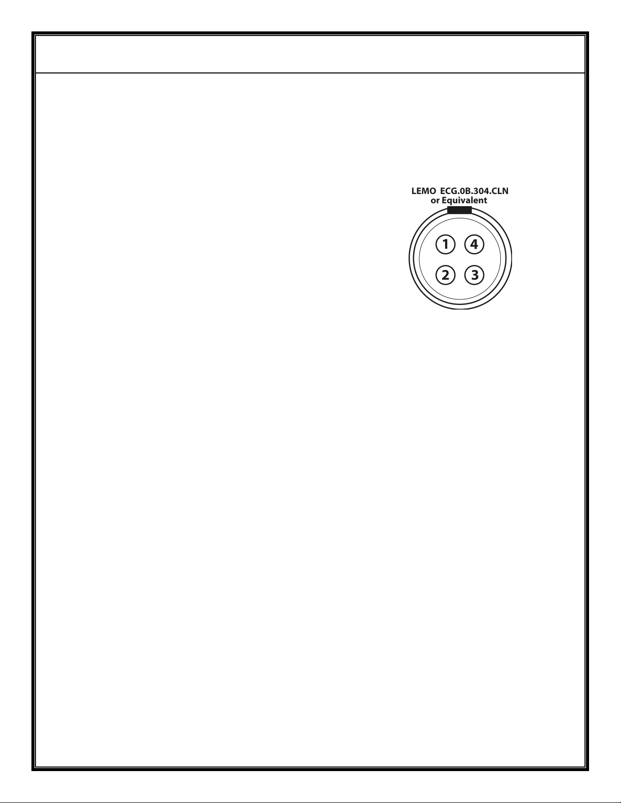
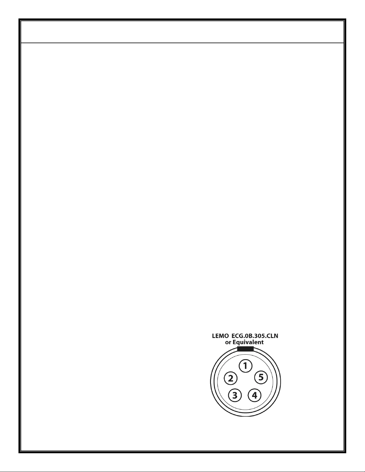
2.1 Power Input – Broadcasting (Option 61) (Circle 3 on rear panel).
a) The power input connector is a 4 pin on the rear panel of the
DX602.
Pin 1 – Power Return
Pin 2 – Video Output
Pin 3 – Video Return
Pin 4 – Power Input (+9Vdc to +16Vdc)
Figure D – Power Input
b) The DX602 operates off a 9Vdc to 16Vdc unregulated voltage
source with a ripple of less than 0.5Vp.p.
c) Input Current at an input voltage of 12Vdc is under 0.7 Amps.
d) Power is switched via an ON/OFF mechanical switch.
e) The DX602 power input is protected against over voltage and
reverse polarity.
Page 8
AVALON RF, INC. Page 5 of 20
DX402/DX502/DX602 User’s Guide & Operating Manual
2.2 Antenna Inputs, total of 2 (Circles 1 & 8 on front panel).
a) DX402: The tuning frequency range is 56MHz-802MHz, VSB
modulated. The antenna connectors are “F” type with a 75 Ω
(ohm) impedance.
b) DX502: The tuning frequency range is 900-928 MHz, FM
modulated. The antenna connectors are “F” type with a 75 Ω
(ohm) impedance. An option extends the range from 900 to 2150
MHz.
c) DX602: The tuning frequency range is 2400-2500 MHz, FM
modulated. The antenna connectors are SMA type with a 50 Ω
(ohm) impedance. An option extends the range from 2150 to 2500
MHz.
2.3 Video Output – Broadcasting (Option 61) (Circle 4 on rear panel)
Video output connector is a BNC type with a 75 Ω (ohm) impedance.
a) Output is NTSC/PAL/RS170A/CCIR baseband from 20 Hz to 5.5
MHz in broadcast mode and 20 HZ to 4.0 MHz in reference mode.
a) Output amplitude is 1 Vp.p. with negative sync tips of 0.3 Vp.p.
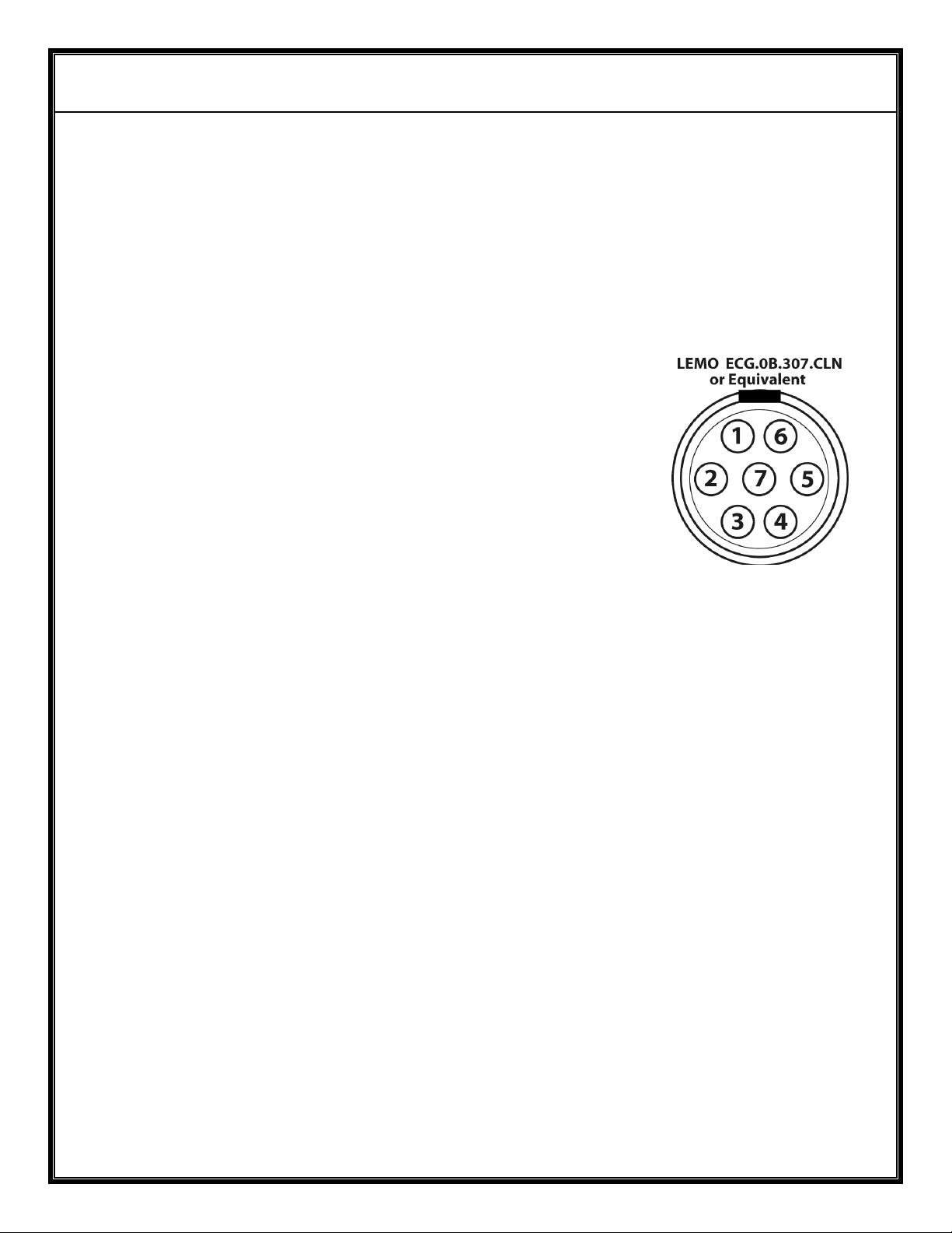
2.4 Audio Outputs – Broadcasting (Option 61) (Circle 2 on rear panel)
Audio output is through a 5 pin connector located on the rear panel.
Pin 1 – Audio Return
Pin 2 – Audio 1 Output
Pin 3 – No Connection
Pin 4 – RS232 Return
Pin 5 – RS232 Input
Figure E – Audio Output(s)
Page 9
AVALON RF, INC. Page 6 of 20
DX402/DX502/DX602 User’s Guide & Operating Manual
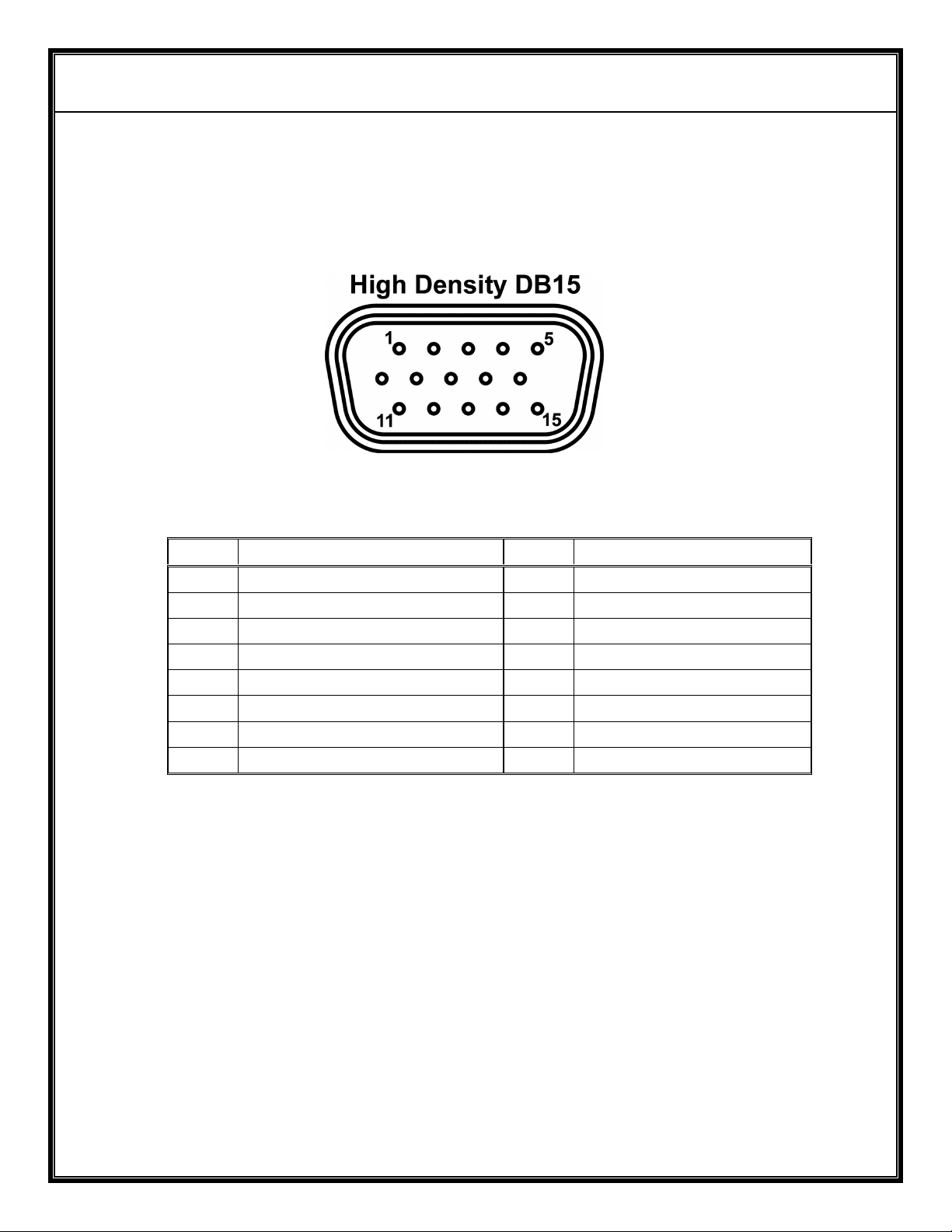
2.5 Digital Wireless Link Data Input – Broadcasting (Option 61)
(Circle 1 on rear panel).
The digital wireless link input connector is a LEMO type
ECG.0B.307.CLN or equivalent:
The connector pin-out is:
Pin 1 – Ground
Pin 2 – Microphone input – Optional
Pin 3 – Speaker output – Optional
Pin 4 – Microphone Bias Output – Optional
Pin 5 – RS485 I/O “A” Input
Pin 6 – RS485 I/O “B” Input
Pin 7 – Ground
2.6 Wireless Digital Link (WDL) Antenna (Circle 6 of Front Panel)
a) The antenna output is a MCX antenna with 50 Ω (ohm)
impedance.
b) The DX602 WDL operating frequency range is 300MHz to
1000MHz.
NOTE
For operation in the USA, the WDL is preset for operation at
433.2MHz.
Figure F – Digital
Wireless Link Data
Input
c) Maximum transmitter output power is 10mW at 433.2MHz.
Page 10
AVALON RF, INC. Page 7 of 20
DX402/DX502/DX602 User’s Guide & Operating Manual
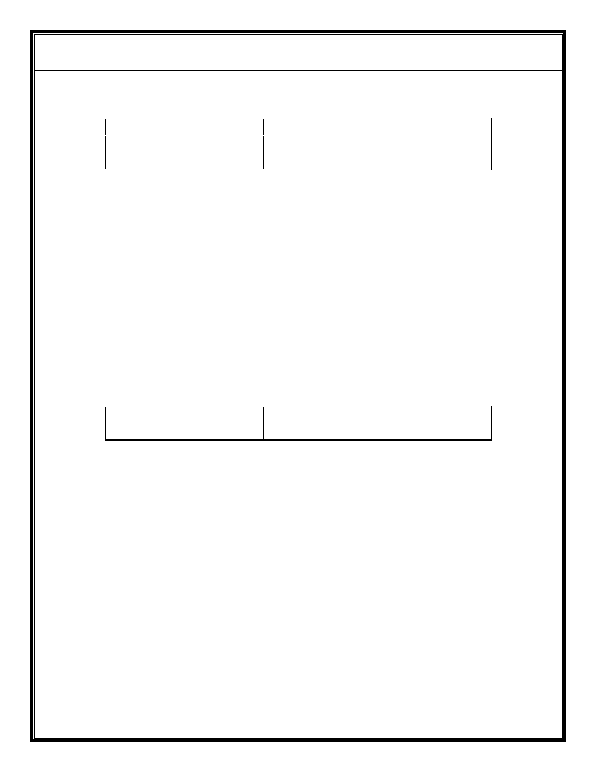
2.7 Interface - Security Version (Figure C, circle 6).
The interface is through a High Density DB15 connector (Figure G)
on the rear panel of the DX602.
Figure G – Interface - Security Version
Pin # Function Pin # Function
1 Power Input 9 Signal Ground
2 Video Output 10 Telemetry 1 Output
3 Video Return Ground 11 Alarm Output
4 Audio 1 Output 12 RS-485 I/O ‘A’
5 Microphone Input 13 RS-485 I/O ‘B’
6 Microphone Bias 14 Telemetry 2 Output
7 RS232 Input 15 Telemetry 3 Output
8 Power Return Ground
2.7.1 Power Input (pins 1 and 8).
a) The DX602 operates off a 9Vdc to 16Vdc unregulated voltage
source with a ripple of less than 0.5Vp.p.
b) Input current at an input voltage of 12Vdc is under 0.6 Amps.
c) Power is switched via an ON/OFF mechanical switch.
d) The DX602 power input is protected against over voltage and
reverse polarity.
2.7.2 Video Output (pins 2 and 3).
a) The DX602 video output is NTSC/PAL/RS170A/CCIR
base-band, 75 Ohm.
b) Output amplitude is 1 V(p.p.) with negative sync tips of 0.3
V(p.p.)
Page 11

AVALON RF, INC. Page 8 of 20
DX402/DX502/DX602 User’s Guide & Operating Manual
2.7.3 Audio Output (pins 4 and 3) )..
The DX602 audio outputs 1V(rms) into a 600 load impedance.
2.7.4 Audio talk back (pins 5, 6 and 9).
The DX602 audio talk back channel has a 100Hz-3.4KHz frequency
response and built-in automatic gain control. It is compatible with an
Electret microphone with separate microphone bias.
The DX602 audio talk back is compatible with the TX623/TX630
2.7.5 Wireless Data Link (WDL) (pins 12 and 13). ).
The WDL is a RS485 half duplex communication link capable of baud
rates of from 1200 baud to 19.2Kbaud.
The DX602 WDL is compatible with a TX623/TX630
2.7.6 Alarm Output (pin 11 and pin 9).
The Alarm output is a dry relay output capable of driving a resistive
load limited to 24V and 1A. It is normally open.
The DX602 alarm is compatible with a TX623/TX630.
2.7.7 Telemetry Output (pins 10, 14 and 15). .
The DX602 has three telemetry outputs. Each output has a voltage
swing of 0V to 1V and an output impedance of 1Kohm with a 0.01uF
capacitor to filter high frequency noise.
The DX602 telemetry is compatible with a TX623/TX630
2.7.8 RS232 Input (pin 7 to pin 9).
The DX602 RS232 input is used to tune the receiver from a remote
computer. It is an asynchronous link operating at 9600 baud, 8 bits,
no parity, ASCII encoded per protocol described in Appendix A.
Page 12
AVALON RF, INC. Page 9 of 20
DX402/DX502/DX602 User’s Guide & Operating Manual
2.8 Size
Configuration Dimensions
The DX602 is intended for mounting in the following configurations:
a) In a CD ROM bay in a DVR
b) Three DX602s on a 19” Retma rack drawer, 1U high.
c) Ten DX602s on a 19” Retma rack drawer, 3U high.
d) Inside other OEM equipment, with or without covers.
2.9 Weight
Net Weight 1 lb. (0.46Kg)
Shipping weight 2 lbs. (0.92Kg)
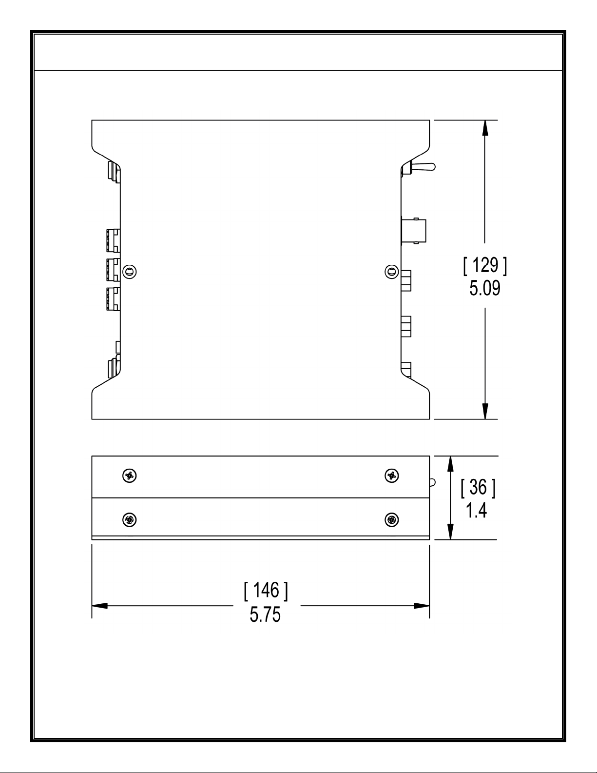
DX602
(See Figure H)
5.09” W x 1.42” H x 5.75” D
129mm x 36mm x 146mm
NOTES
Page 13
AVALON RF, INC. Page 10 of 20
DX402/DX502/DX602 User’s Guide & Operating Manual
Figure H – DX602 Mechanical Specifications - Inches [mm]
Page 14

AVALON RF, INC. Page 11 of 20
DX402/DX502/DX602 User’s Guide & Operating Manual
2.10 Environmental Conditions.
The DX602 is designed to meet the following environmental
conditions:
a) Operating temperature
b) Storage temperature
c) Vibration 1.5G, from 10Hz to 2KHz, sine
d) Shock 15G, 25msec, half sine wave,
e) Humidity 5 to 95%, non-condensing
f) Inclination Any
g) Altitude -1500 feet to 15,000 feet
-4° to 122° F
(-20° to 50° C)
-13° to 150° F
(-25° to 65° C)
wave, three axis
three axis
(-450 meter to 4,500 meter)
Page 15

AVALON RF, INC. Page 12 of 20
DX402/DX502/DX602 User’s Guide & Operating Manual
3. Operating Instructions
3.1 Human Interface.
3.1.1 Front Panel Frequency Select Switches (Circles 3,4,5 on figure A)
The DX602 front panel switches have the following functions:
a) Frequency select (tuning) in a standard DX602.
b) Electronic Identification Number (EIN) in units with auto
synthesizing.
3.1.2 Front Panel Indicators (Circles 2,7 on figure A).
The DX602 front panel includes antenna select LEDs. One Green
LED for each antenna. The antenna LEDs indicate which of the
antennas has been selected for its best video.
3.2 Operating the DX602.
The DX602 has the following user accessible functions:
3.2.1 On/Off
3.2.2 Tuning via front panel rotary switches (Circles 3,4,5 on figure A).
a) DX402
The DX402 can be tuned:
Channel number (2-69) 902-969 on switches
Frequency in MHz 056-802 (first digit not “9”).
Auto synt. C51-FFF
b) DX502
The DX502 is tuned to a carrier frequency, encoded as follows:
900MHz to 999MHz A00-A99 on switches
1000MHz to 1999MHz 000-999
2000MHz to 2099MHz B00-B99
2100MHz to 2150MHz C00-C50
EIN numbers for auto synt. C51-FFF
c) DX602
2150MHz to 2500MHz 150-500 on switches
EIN numbers for auto synt. C51-FFF
Page 16

AVALON RF, INC. Page 13 of 20
DX402/DX502/DX602 User’s Guide & Operating Manual
3. Operating Instructions (continued).
3.2.2 Tuning (continued).
d) Remotely via the RS232 interface (Optional).
Consult Appendix A.
e) Self tuning via the auto synthesizing function (Optional).
If the front panel switches are set to values between C51 and FFF
(That’s about 700 combinations), the DX602 and its corresponding
TX623/TX630 will look for the first available channel in a
predefined list of channels.
Page 17

AVALON RF, INC. Page 14 of 20
DX402/DX502/DX602 User’s Guide & Operating Manual
4. Ordering Information
DX402 – Basic System
DX502 – Basic System
DX602 – Basic System
Every DX602 comes with the following standard features and
accessories.
4.1 One DX402 or DX502 or DX602 in a ZIPLOCK ESD bag.
The receiver has one video and one audio channel.
4.2 One BX002U 12V low noise regulated AC adapter for 110Vac/60Hz.
4.3 A user manual (the one you’re reading).
4.4 A warranty card.
4.5 One reusable carton with foam lining.
Page 18

AVALON RF, INC. Page 15 of 20
DX402/DX502/DX602 User’s Guide & Operating Manual
4.6 Optional features:
Option 00 European version.
Includes a 230VAC power adapter and calibration
for PAL.
Option 01 Remote programming.
Includes the RS232 interface. Consult Appendix A
for programming instructions.
Option 02 Remote synthesizing
This option automatically changes the operating
frequency of a TX630 companion transmitter to
match the change in tuning frequency of its DX602.
It requires Option 11.
Option 04 Extended tuning range (DX502 & DX602 only)
DX502 – 900MHz to 2.150GHz
DX602 - 2.150GHz to 2.500GHz
Option 11 Two way serial communication channel.
Option 31 Audio talk back input
Option 41 Alarm output
Option 51 Telemetry output.
Option 61 Broadcasting version (with Lemo connectors)
Option 99 Power to an external LNA (DX502 Only).
Option R3 Rack mount kit to mount 3 DX602 in a rack.
Option R10 Rack mount kit to mount 10 DX602 in a rack.
Includes a 110/230VAC to 12V/10A L.V.P.S.
Option PC Bracket to mount DX602 in an IBM/PC
Page 19
AVALON RF, INC. Page 16 of 20
DX402/DX502/DX602 User’s Guide & Operating Manual
4.7 Optional accessories
4.7.1 Antennas.
Each receiver requires two (2) antennas. Higher antenna gain yields
longer range with limitations on reception “viewing angle”.
Ordering information:
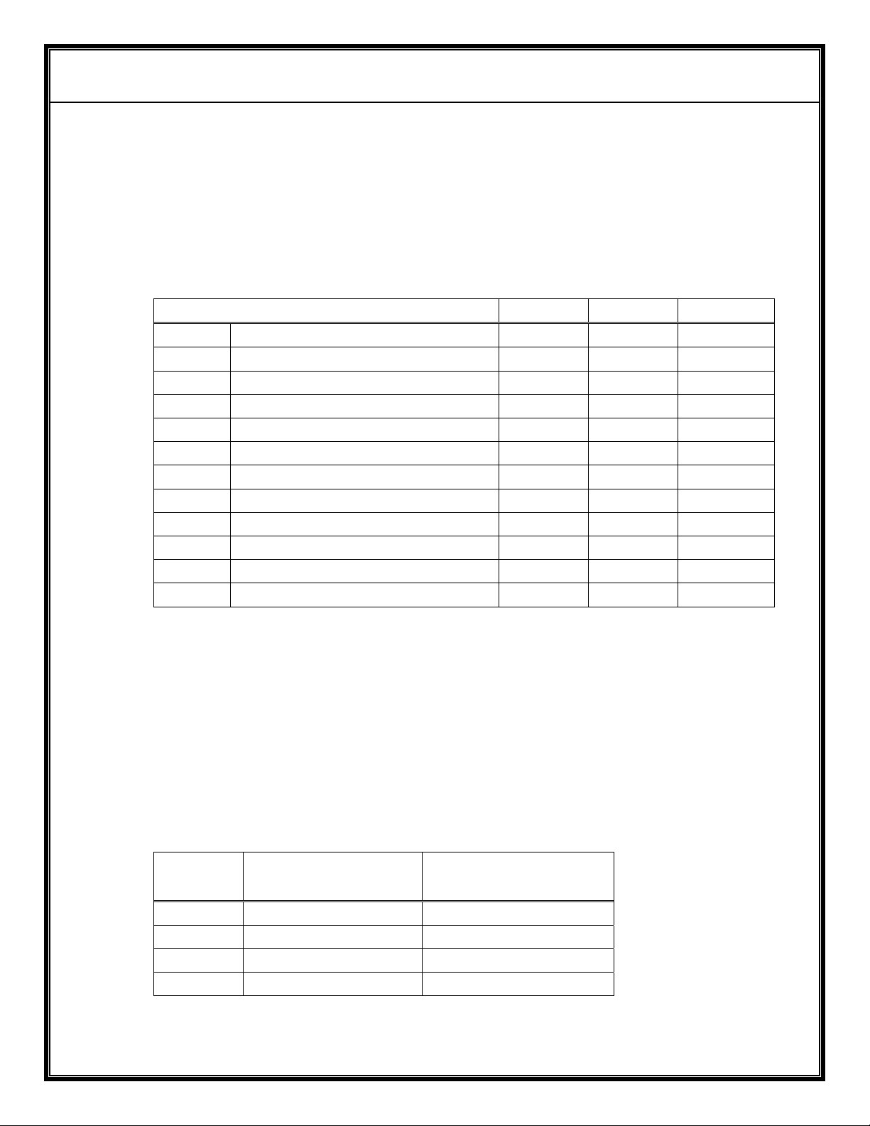
Description DX402 DX502 DX602
2dbi Omnidirectional AX402 AX502 AX602
2dbi omni circular polarized AX602R
5dbi Omnidirectional AX405 AX505 AX605
6dbi hemispheric patch AX406 AX506
9.5dbi panel antenna AX609
10dbi circular polarized(RH) patch AX610R
10dbi circular polarized(LH) patch AX610L
11dbi log periodic antenna AX411
13dbi panel antenna AX513 AX613
15dbi panel antenna AX615
18dbi panel antenna AX618
24dbi parabolic antenna AX624
4.7.2 Antenna cables.
These cables connect the receiver to its antennas. If a system
requires splitters, these cables connect the antennas to the splitters.
DX602: Times Microwave LMR-240 50 Ω (ohm) or equivalent are
recommended for runs up to 30ft and LMR-400 50 Ω (ohm) for runs
from 20ft to 50ft.
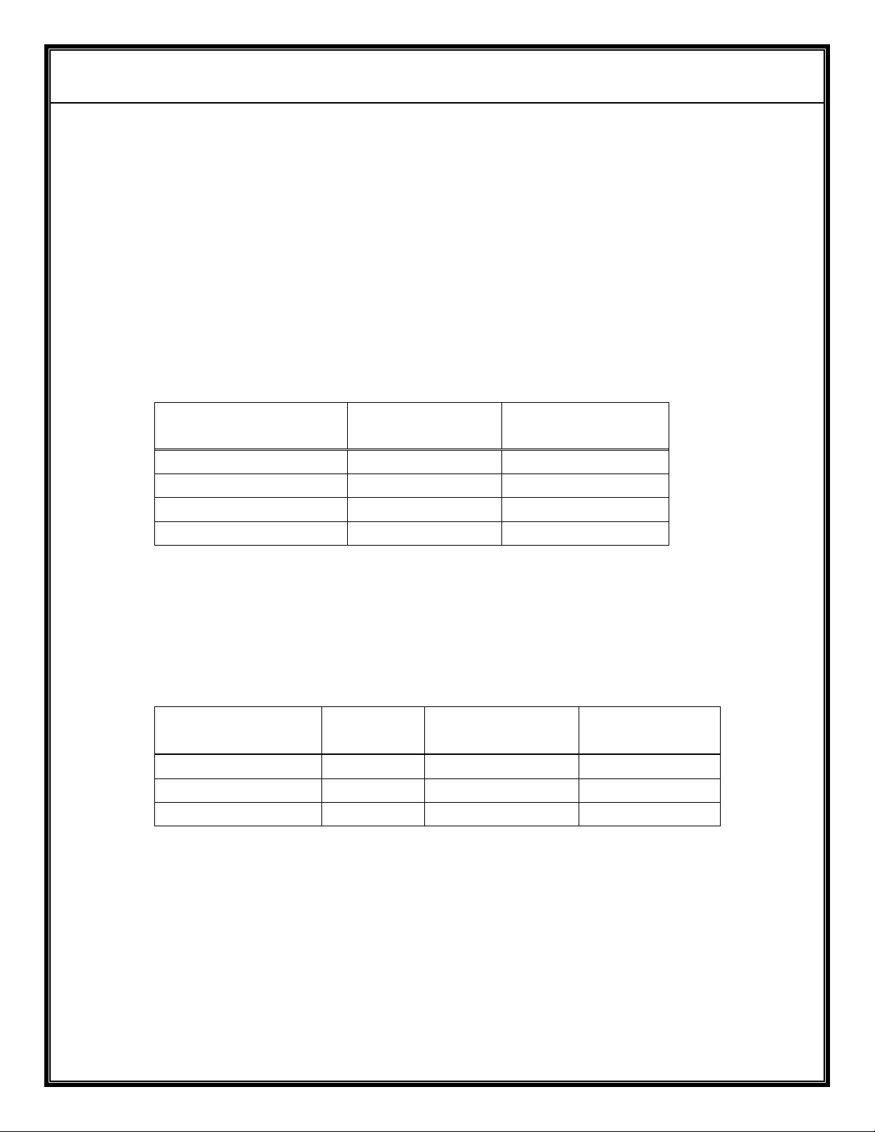
Ordering Information:
DX402/DX502
Length
F-F/75Ω (ohm)
5’ CBLFF-5 CBLNS-5
15’ CBLFF-15 CBLNS-15
30’ CBLFF-30 CBLNS-30
50’ CBLFF-50 CBLNS-50
DX602
N-SMA/50Ω (ohm)
Page 20
AVALON RF, INC. Page 17 of 20
DX402/DX502/DX602 User’s Guide & Operating Manual
4.7.3 Antenna cables for the Wireless Digital Link (WDL)
The WDL antenna cable is a MCX to BNC 50 OHM cable.
4.7.4 Splitters
When a set of four antennas feeds more than one receiver, it is
convenient to split the signal from each antenna to all receivers at the
same location.
Ordering information:
Splitter type
1 to 2 (two DX..2) SP2F SP2S
1 to 3 (three DX..2) SP3F SP3S
1 to 4 (four DX..2) SP4F SP3S
1 to 8 (eight DX..2) SP8F SP8S
4.7.5 Splitter to receiver cables.
The use of splitters requires jumper cables from every splitter output
to every receiver antenna input. Ordering information for a four
receiver system:
Number of DX..2
Receivers
2 8 CBLFF-2 CBLSS-2
3 12 CBLFF-2 CBLSS-2
4 16 CBLFF-2 CBLSS-2
DX402/DX502
Number
of cables
DX602
(F-F)
DX402/DX502 DX602
(SMA-SMA)
4.7.6 Wireless Digital Link (WDL) combiner cables.
A RF signal combiner feeds one DWL antenna and antenna cable
from is used to drive the DWL signals from more than one DX..2
receiver to a single DWL antenna and antenna cable.
Page 21
AVALON RF, INC. Page 18 of 20
DX402/DX502/DX602 User’s Guide & Operating Manual
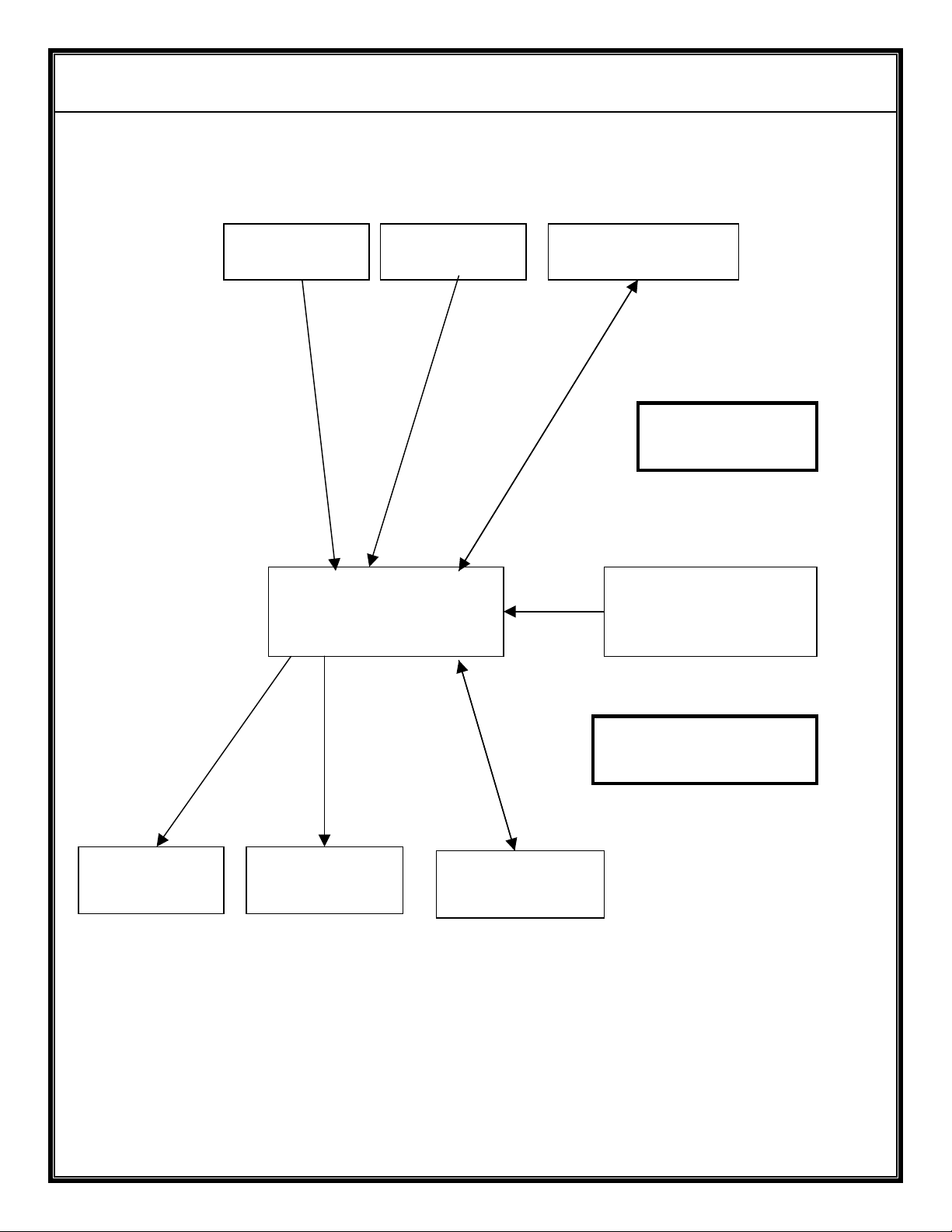
ANTENNA 1 ANTENNA 2
DX502 or DX602
BACK CHANNEL
ANTENNA
ANTENNA
CABLES (2/3)
110VAC
POWER SUPPLY
VIDEO OUT
(BNC)
Figure I – Block Diagram of Basic System with a Single
AUDIO OUT
(LEMO 0B-5)
DATA
(LEMO 0B-7)
DX402/DX502/DX602 Receiver
LOW FREQUENCY
CABLES
Page 22
AVALON RF, INC. Page 19 of 20
DX402/DX502/DX602 User’s Guide & Operating Manual
ANTENNA 1 ANTENNA 2
ANTENNA
CABLES
SPLITTER
1:4
DX502/DX602
SPLITTER
1:4
DX502/DX602 DX502/DX602 DX502/DX602
2 or 3(*)
CABLES
BACK CHANNEL
ANTENNA
COMBINER
4:1
SPLITTER TO RECEIVER JUMPER CABLES
2 or 3(*) cables per receiver
A D PV
2/3(*) CABLES per receiver
(*) With BACK CHANNEL
12VDC POWER
DISTRIBUTION
Figure J – Block Diagram of System with
Four DX402/DX502/DX602 Receivers
110VAC
TO 12VDC
LINE
Page 23

AVALON RF, INC. Page 20 of 20
DX402/DX502/DX602 User’s Guide & Operating Manual
Appendix A – Remote Programming Option
1. Interface.
The DX402/DX502/DX602 can be remotely programmed via an
RS232C interface. The data rate is set to 9600 Baud, 8 bits, no
parity, 1 stop bit and no handshaking signals. Data is ASCII encoded.
2. Protocol.
<Frequency> <CR> where frequency is any frequency in the tuning
range of the receiver in increments of 250KHz.
E.G.: DX602 -> 2400 <CR> will tune in to 2400MHz
2413.25 <CR> will tune in to 2413.25MHz
 Loading...