

Page 1
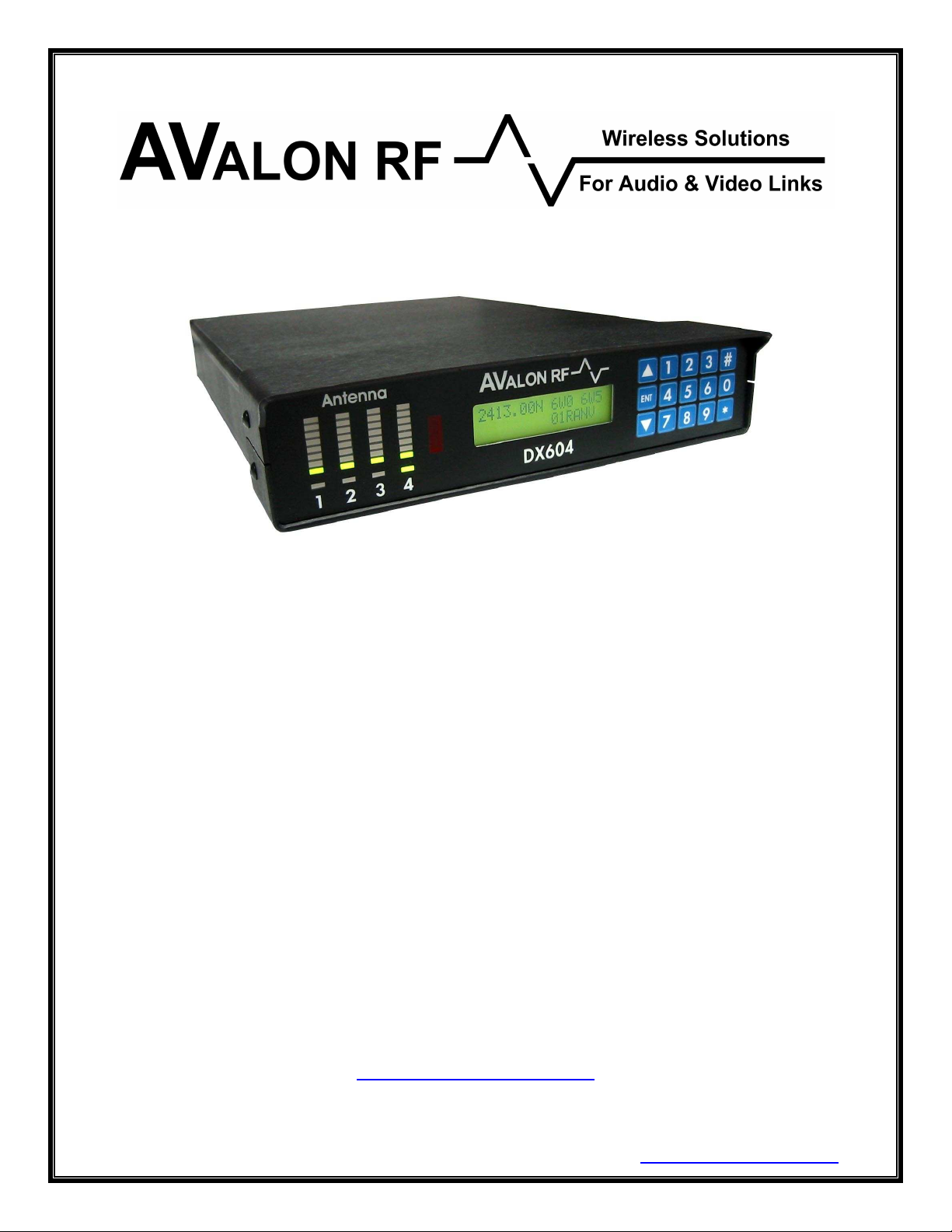
DX404 / DX504 / DX604
Four Antenna Diversity
Receivers
User's Guide & Operating Manual
AV010220/1-000
REV. A3 - 1 April 2005
Edited by Eli Weinstein
http://www.avalonrf.com/
Avalon RF, Inc. • 344 Coogan Way • El Cajon, CA 92020
Phone: (619) 401-1969 • Fax: (619) 401-1971 • Email: [email protected]
Page 2

AVALON RF, INC. Page ii
DX404/DX504/DX604 User’s Guide & Operating Manual
Table of Contents
1. General .................................................................................................1
Figure A – Front Panel..........................................................................2
Figure B – Rear Panel...........................................................................3
2. Specifications........................................................................................4
Power Input...........................................................................................4
Figure C – Power Input .....................................................................4
Antenna Inputs......................................................................................5
Video Output.........................................................................................5
Audio Outputs.......................................................................................5
Figure D – Audio Output(s) ...............................................................6
Digital Wireless Link Data Input............................................................6
Figure E – Digital Wireless Link Data Input.......................................6
Digital Wireless Link Antenna Output ...................................................6
Size.......................................................................................................7
Weight...................................................................................................7
Figure F – DX604 Mechanical Specifications .......................................8
Inches [mm]...........................................................................................8
Figure G – DX604 (Option R) Mechanical Specifications .....................8
Inches [mm]...........................................................................................8
Environmental Conditions.....................................................................9
3. Operating Instructions.........................................................................10
Human Interface .................................................................................10
Front Panel Keypad.........................................................................10
Front Panel Indicators .....................................................................10
Front Panel Display.........................................................................10
Front Panel Interface.......................................................................11
Operating the DX604..........................................................................11
Tuning .............................................................................................11
Frequency scanning........................................................................12
Tuner Select....................................................................................12
Turning ON or OFF the LCD backlight............................................13
Locking the keypad .........................................................................13
Setup ..................................................................................................14
Tuning the audio sub-carrier frequencies........................................14
Setting the audio sub-carrier bandwidth..........................................14
Changing the video bandwidth........................................................15
Inverting the polarity of the video output .........................................15
Page 3

AVALON RF, INC. Page iii
DX404/DX504/DX604 User’s Guide & Operating Manual
Adding the audio sub-carriers to the video output...........................15
Assigning an EIN (Electronic Identification Number).......................16
4. Error conditions and Prompts..............................................................17
Power fault indicator........................................................................17
Battery-low warning.........................................................................17
Internal errors..................................................................................17
Keypad entry errors.........................................................................17
5. Ordering Information ...........................................................................18
Optional features.............................................................................19
Optional accessories.......................................................................20
Figure H – Block Diagram – Basic System w/ Single Receiver.......22
Figure J – Block Diagram – Basic System with Four Receivers......23
Appendix A – LCD format ..........................................................................24
Appendix B – Remote Programming Option
Appendix C – BIT codes
.......................................................................28
....................................26
Page 4

AVALON RF, INC. Page 1 of 28
DX404/DX504/DX604 User’s Guide & Operating Manual
1. General
The DX404/DX504/DX604 are rugged 4-antenna ‘true’ diversity video
and audio receivers intended for demanding high end video
applications.
The DX404 NTSC model tuning range is from 56MHz to 802.25MHz
The DX404 PAL model tuning range is from 56MHz to 860MHz.
The DX504 tuning range is from 900 MHz to 928 MHz (2150 MHz
with Option 4)
The DX604 tuning range is from 2350 MHz to 2500 MHz (2150 to
2500 MHz with Option 4).
All receivers have the following standard feature:
One FM modulated (AM/VSB for DX404) video channel
Two (1 for DX404) FM modulated audio channels
And the following optional features:
Broadcasting industry options
* Talk back audio channel
* Remote control of the receiver via RS232
Security industry options
* Serial communication (RS485/RS422) input port for Pan/Tilt/Zoom
control
* Alarm output
* 3 analog telemetry outputs
* Remote control of the receiver via RS232
Unless explicitly stated, every reference in this document to the
DX604 also implies the DX404 and DX504. The main difference
between the models is the frequency range.
Page 5
AVALON RF, INC. Page 2 of 28
DX404/DX504/DX604 User’s Guide & Operating Manual
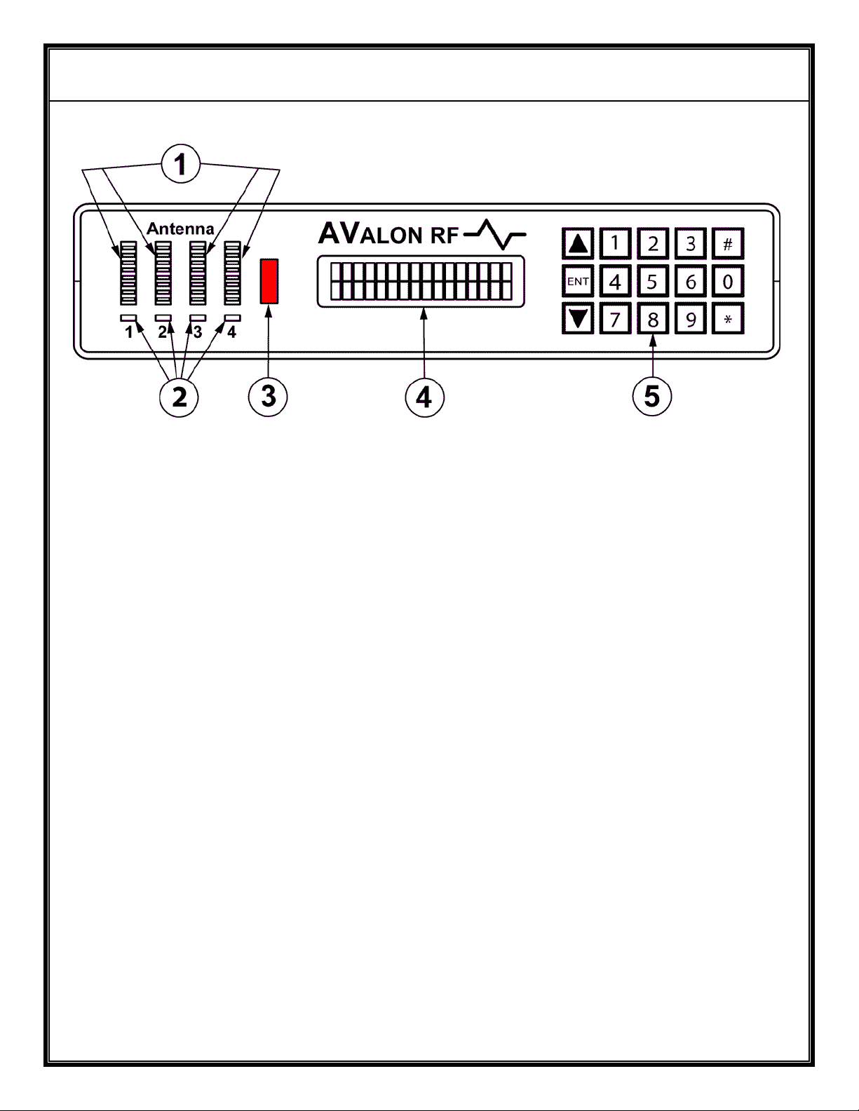
Figure A – Front Panel
DX404/DX504/DX604 Controls, Indicators and Connectors
1 Signal Quality Indicators
2 Antenna Select LED
3 IRDT Receiver
4 LCD Display
5 Keypad
Page 6
AVALON RF, INC. Page 3 of 28
DX404/DX504/DX604 User’s Guide & Operating Manual
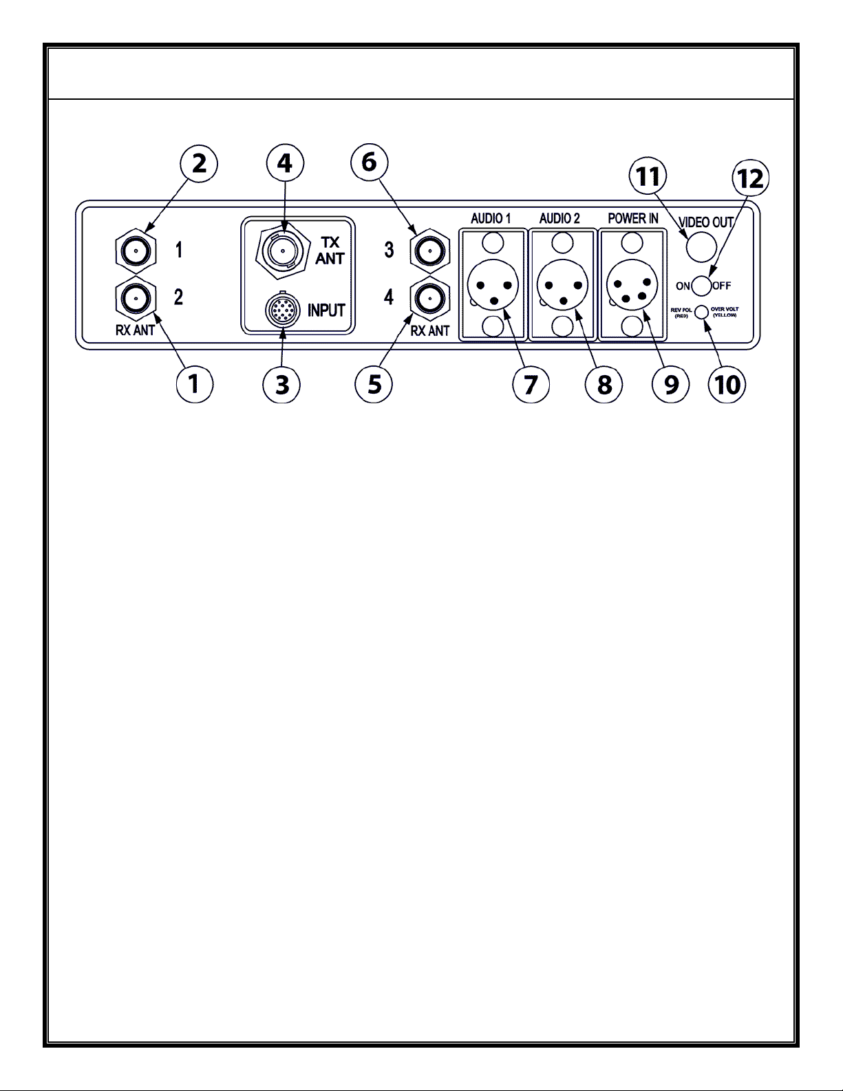
Figure B – Rear Panel
DX404/DX504/DX604 Controls, Indicators and Connectors
1, 2, 5, 6 Antenna Inputs (Section 2.2)
3 Digital Wireless Link Interface Connector (section 2.5)
4 Digital wireless link Antenna Output (section 2.6)
7, 8 Audio Outputs (section 2.4)
9 Power & RS232 Input (Section 2.1)
10 Power Fault Indicator
11 Video Output (Section 2.3)
12 On/Off Switch
Page 7
AVALON RF, INC. Page 4 of 28
DX404/DX504/DX604 User’s Guide & Operating Manual
2. Specifications
2.1 Power Input (Circle 9 on rear panel).
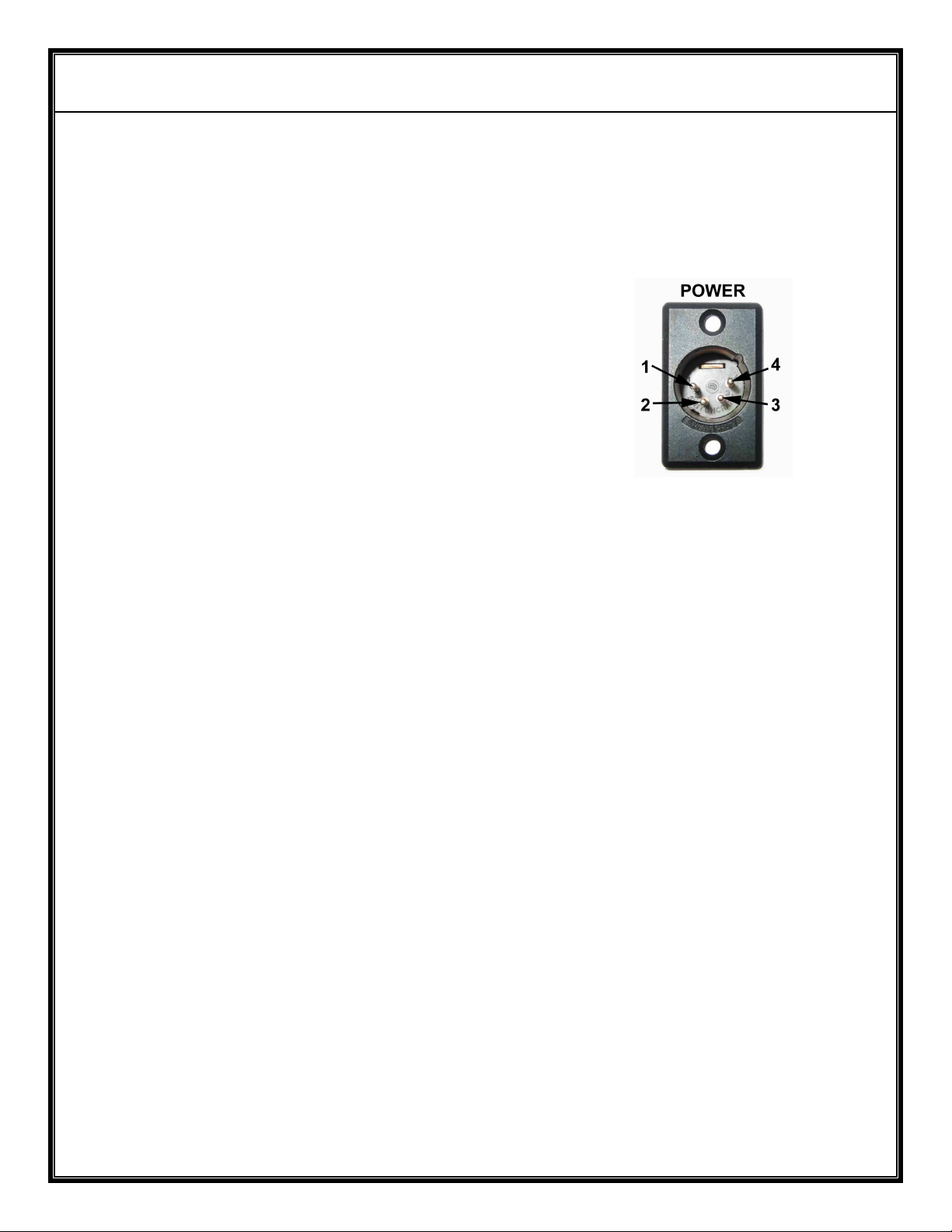
a) The power input connector is a XLR 4 pin on the rear panel of the
DX604.
Pin 1 – Ground
Pin 2 – RS232 Interface (Transmit)
Pin 3 – RS232 Interface (Receive)
Pin 4 - +9Vdc to +16Vdc
Figure C – Power Input
b) The DX604 operates off a 9Vdc to 16Vdc unregulated voltage
source with a ripple of less than 0.5Vp.p.
c) Input Current is under 1 Amp at an input voltage of 12Vdc.
d) Power is switched via an ON/OFF mechanical switch.
e) The DX604 power input is protected against over voltage and
reverse polarity.
A bi-color LED on the rear panel indicates the condition. Yellow
indicates over voltage and Red indicates reverse polarity.
NOTE
f) The RS232 interface option on pins 2 and 3 is used to remotely
program and setup the DX604 as described in Appendix B.
Page 8
AVALON RF, INC. Page 5 of 28
DX404/DX504/DX604 User’s Guide & Operating Manual
2.2 Antenna Inputs, total of 4 (Circles 1,2,5,6 on rear panel).
a) DX404: The tuning frequency range is 56MHz-802/860MHz,
AM/VSB modulated. The antenna connectors of the NTSC model
are “F” type with a 75 Ω (ohm) impedance. The PAL model has
RCA connectors.
b) DX504: The tuning frequency range is 900-928 MHz, FM
modulated. The antenna connectors are “F” type with a 75 Ω
(ohm) impedance.
c) DX604: The tuning frequency range is 2350-2500 MHz, FM
modulated. The antenna connectors are SMA type with a 50 Ω
(ohm) impedance.
2.3 Video Output (circle 11 on rear panel)
The video output through a 75 Ω (ohm) BNC connector.
a) Output is NTSC/PAL/RS170A/CCIR baseband from 20 Hz to 5.5
MHz.
b) Output amplitude is 1 Vp.p. with negative sync tips of 0.3 Vp.p.
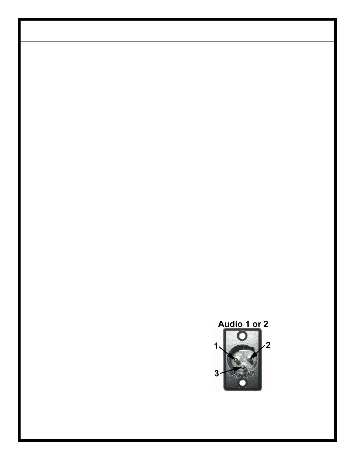
2.4 Audio Outputs (Circles 7,8 on rear panel)
Both audio outputs are XLR 3 pin connectors located on the rear
panel.
Pin 1 – Ground
Pin 2 – Audio Output (P)
Pin 3 – Audio Output (N)
Figure D – Audio Output(s)
Output is 1 V (peak to peak) into 600 Ω (ohm), balanced.
Page 9
AVALON RF, INC. Page 6 of 28
DX404/DX504/DX604 User’s Guide & Operating Manual
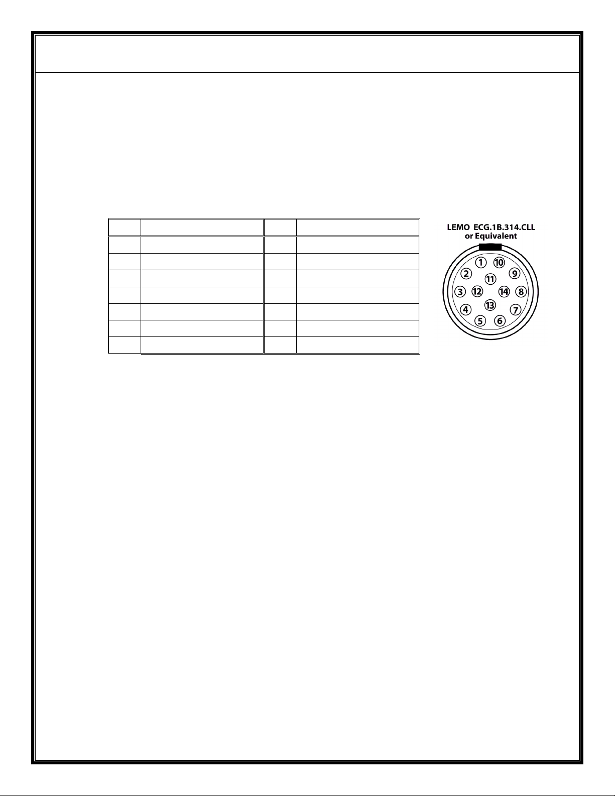
2.5 Digital Wireless Link Data Input.
The digital wireless link input connector is a LEMO type
ECG1B3147CLL or equivalent. The mating connector is a
FGG1B314CLAD62
The connector pin-out is:
Pin Pin
1 Speaker Left 8 Telemetry 1
2 Microphone 9 Telemetry 2
3 Speaker Left 10 Telemetry 3
4 Microphone Bias 11 Ground
5 RS485 I/O “A” 12 Ground
6 RS485 I/O “B” 13 N/C
7 Alarm 14 N/C
2.6 Digital Wireless Link Antenna Output
The antenna output is a BNC antenna with 50 Ω (ohm) impedance.
Figure E – Digital
Wireless Link
Data Input
Page 10
AVALON RF, INC. Page 7 of 28
DX404/DX504/DX604 User’s Guide & Operating Manual
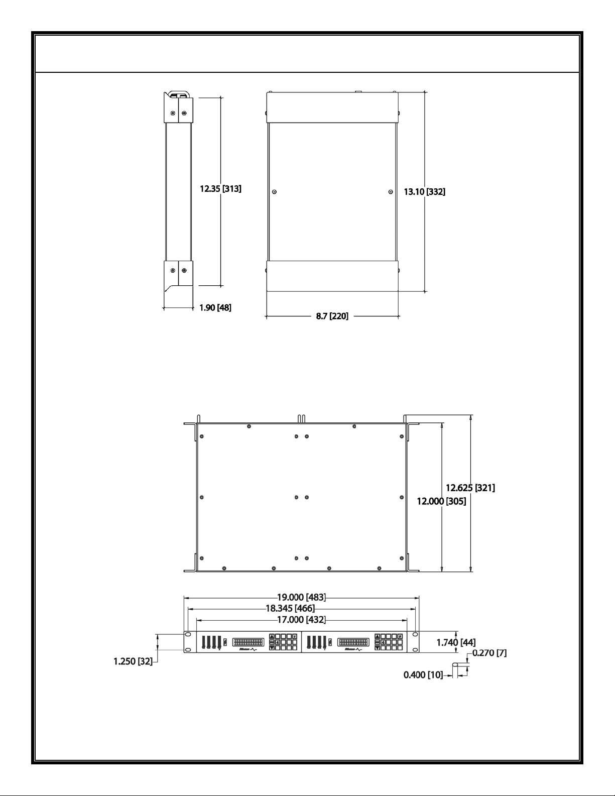
2.7 Size
The DX404/DX504/DX604 are available in two configurations:
Configuration Dimensions
Without Removable Hood
8.5” W x 1.75” H x 12.125” D
Single DX604
(See Figure F)
Dual DX604 (Option R)
(See Figure G)
The DX604 is intended for use in a desktop configuration.
The dual DX604 is intended for mounting in a RETMA 19”
rack and requires a height of 1U.
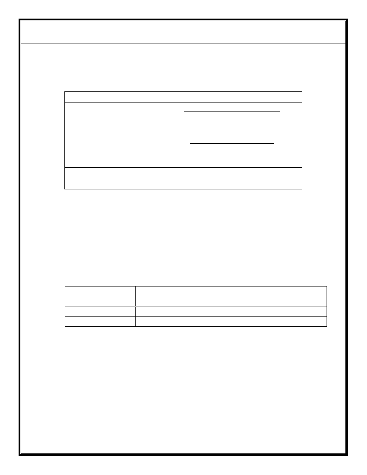
2.8 Weight
Desktop (single) Dual (Option R)
Description
216mm x 45mm x 308mm
With Removable Hood
8.7” W x 1.9” H x 13.1” D
221mm x 48mm x 333mm
17” W x 1.75” H x 12.125” D
432mm x 44.5mm x 308mm
NOTES
Rack mount
Net 4.3 lbs (1.90Kg) 8.5 lbs (3.80Kg)
Shipping weight 8.5 lbs (3.80Kg) 17 lbs (7.6Kg)
Page 11
AVALON RF, INC. Page 8 of 28
DX404/DX504/DX604 User’s Guide & Operating Manual
Figure F – DX604 Mechanical Specifications
Inches [mm]
Figure G – DX604 (Option R) Mechanical Specifications
Inches [mm]
Page 12

AVALON RF, INC. Page 9 of 28
DX404/DX504/DX604 User’s Guide & Operating Manual
2.9 Environmental Conditions.
The DX604 is designed to meet the following environmental
conditions:
a) Operating temperature
b) Storage temperature
c) Vibration 1.5G, from 10Hz to 2KHz, sine
d) Shock 15G, 25msec, half sine wave,
e) Humidity 5 to 95%, non-condensing
f) Inclination Any
g) Altitude -1500 feet to 15,000 feet
(-450 meter to 4,500 meter)
-4° to 122° F
(-20° to 50° C)
-13° to 150° F
(-25° to 65° C)
wave, three axis
three axis
Page 13
AVALON RF, INC. Page 10 of 28
CH #39 NTSC
01RANVL
2407.50N 6W0 6W5
01RANVL
DX404/DX504/DX604 User’s Guide & Operating Manual
3. Operating Instructions
3.1 Human Interface.
3.1.1 Front Panel Keypad (Circle 5 on figure A)
All manual setup functions are entered via the keypad.
3.1.2 Front Panel Indicators (Circles 1,2 on figure A).
The DX604 front panel includes the following indicators:
a) Signal quality indicators for each antenna via an 8 segment LED
bar graph. The higher the illuminated LED, the better the signal
from the antenna.
b) Antenna select LED. One Green LED for each antenna. The
antenna LED indicates which of the antennas has been selected
for its best video.
3.1.3 Front Panel Display (circle 4 on figure A)
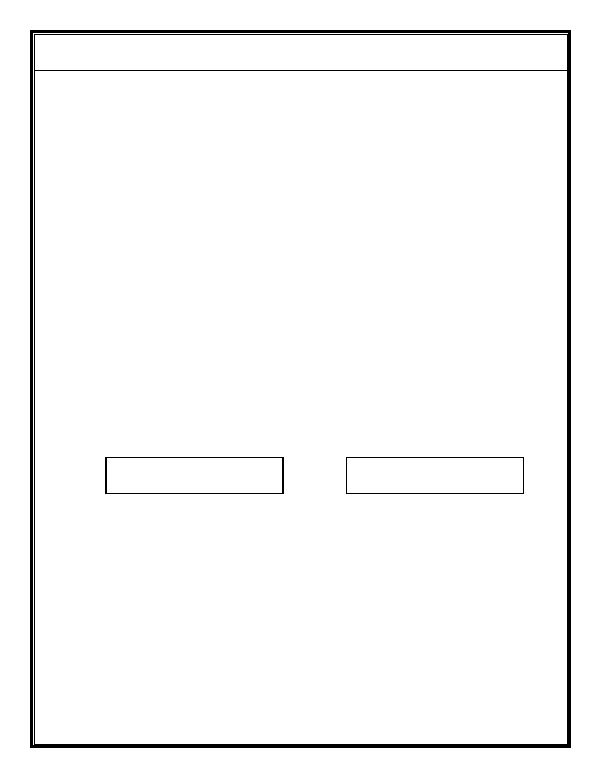
The DX604 has a 2 line LCD display, each line capable of displaying
up to 16 alphanumeric characters.
Typical DX404 display Typical DX504/DX604 display
The top line of the LCD displays the frequencies of the video carrier
and of the two audio sub-carriers (on the DX504/DX604 only) and the
channel number on the DX404. The format of the second line is
explained in Appendix A.
The display can be turned ON or OFF (see section 3.2.4).
Page 14

AVALON RF, INC. Page 11 of 28
DX404/DX504/DX604 User’s Guide & Operating Manual
3.1.4 Front Panel Interface
The DX604 has an optional IRDT serial interface, capable of
communicating with a PDA at a distance up to 3 feet.
3.2 Operating the DX604.
The commonly used receiver commands are:
* Tuning
* Frequency scanning
* Tuner select (Excluding tuners from the diversity)
* Turning the display on or off
* Locking the keypad.
3.2.1 Tuning
<FREQ> <ENTER> tunes in to the desired frequency. The <*> key is
used as a decimal point.
The DX404 NTSC model tuning range is from 56MHz to 802.25MHz
The DX404 PAL model tuning range is from 56MHz to 860MHz.
The DX504 tuning range is from 900 MHz to 928 MHz (2150 MHz
with Option 4).
The DX604 tuning range is from 2350 MHz to 2500 MHz (2150 to
2500 MHz with Option 4).
E.G.:
802*25<ENTER> tunes a DX404 to 802.25MHz (Channel 69)
912<ENTER> tunes a DX504 to 912MHz.
2412<ENTER> tunes a DX604 to 2.412GHz.
The tuned-in frequency appears on the top left of the LCD as
explained in Appendix A.
If <FREQ> is out of the tuning range, the receiver will display
“INVALID” and default to the last tuned-in frequency.
E.G.:
912<ENTER> is beyond the tuning range of the DX604 and will be
rejected.
Page 15

AVALON RF, INC. Page 12 of 28
DX404/DX504/DX604 User’s Guide & Operating Manual
#<CHANNEL> <ENTER> tunes in to the desired channel (DX404
only).
The valid channels for the DX404 NTSC model are 2-69.
The valid channels for the DX404 PAL model are 2-12 and 21-70.
E.G.:
#25<ENTER> tunes a DX404 to channel 25.
3.2.2 Frequency scanning.
<UP> tunes to the next higher frequency (or Channel for DX404).
<DOWN> tunes to the next lower frequency (or Channel for DX404).
Holding down the <UP> or <DOWN> keys changes the frequency (or
channel) repeatedly.
The factory preset step increment/decrement step is 0.25MHz and
may be changed by typing the following sequence:
*92 <STEP> <ENTER>
Where
<STEP> is a 4 digit number from 0025 to 9975, corresponding to
a minimum step of 0.25MHz and a maximum of 99.75MHz.
E.G.:
*92 1 <ENTER> will increment/decrement 1MHz at a time.
*92 12 <ENTER> will increment/decrement 12MHz at a time.
*92 0025 <ENTER> will increment/decrement 0.25MHz at a time.
*92 1225 <ENTER> will increment/decrement 12.25MHz at a time.
3.2.3 Tuner Select
The DX604 is factory preset to automatically select one of the 4
tuners (The one with the best signal). The number of tuners
participating in the diversity process can be limited via the following
function (<TN> is any tuner number from 1 to 4):
*1# <TN> <ENTER> selects one tuner only.
*1# <TN> <TN> <ENTER> selects two tuners.
*1# <TN> <TN> <TN> <ENTER> selects three tuners out of four.
*1 <ENTER> selects all four tuners (normal mode)
E.G.:
*1#1 <ENTER> locks the output to tuner 1 and stops the diversity.
Page 16

AVALON RF, INC. Page 13 of 28
DX404/DX504/DX604 User’s Guide & Operating Manual
*1#12 <ENTER> eliminates tuners 3 and 4 from the diversity
*1#123 <ENTER> eliminates tuner 4 from the diversity
*1 <ENTER> includes all four tuners in the diversity process.
A A/M indication is shown on the LCD display, line 2 as explained in
Appendix A. This setting is not saved at power off.
3.2.4 Turning ON or OFF the display.
*# <ENTER> toggles the display ON or OFF.
3.2.5 Locking the keypad.
This feature is used to prevent accidental change of setup.
*077 <ENTER> locks the keypad.
*055 <ENTER> unlocks the keypad.
The LCD displays a “L” at the bottom right if the keypad is locked.
Page 17

AVALON RF, INC. Page 14 of 28
DX404/DX504/DX604 User’s Guide & Operating Manual
3.3 Setup.
3.3.1 Tuning the audio sub-carrier frequencies (DX504/DX604 only).
The Audio1 sub-carrier frequency is factory preset to 6 MHz.
The Audio2 sub-carrier frequency is factory preset to 6.5MHz.
The audio sub-carrier frequencies can be tuned anywhere between
5MHz to 7MHz in increments of 10KHz.
Audio1: *21# <FREQ> <ENTER>
Audio2: *22# <FREQ> <ENTER>
Where <FREQ> is from 500 to 700 (the first digit represents
megahertz & the last digit represents 10’s of kilohertz), tunes the
audio sub-carrier to the desired frequency. If the ‘#’ character and
<FREQ> are omitted, the sub-carriers will tune to the factory preset.
E.G.:
*21# 665 <ENTER> tunes Audio1 to 6.65 MHz.
*22# 700 <ENTER> tunes Audio2 to 7MHz
*22 <ENTER> tunes Audio2 back to 6.5MHz
3.3.2 Setting the audio sub-carrier bandwidth.
The audio IF bandwidth can be set to narrow for 75 KHz deviation
or wide for 125 KHz deviation.
Audio1: *211 <ENTER> sets Audio1 bandwidth to Narrow.
*210 <ENTER> sets Audio1 bandwidth to Wide.
Audio2: *221 <ENTER> sets Audio2 bandwidth to Narrow.
*220 <ENTER> sets Audio2 bandwidth to Wide.
Selecting an incorrect audio bandwidth results in a low and distorted
audio output.
Page 18

AVALON RF, INC. Page 15 of 28
DX404/DX504/DX604 User’s Guide & Operating Manual
3.3.3 Changing the video bandwidth (DX504 only).
The DX404 video bandwidth is factory preset to 5MHz. The DX604
video bandwidth is factory preset to 16 MHz. The DX504 video
bandwidth can be field changed from 16MHz to 27 MHz and back.
*32 <ENTER> changes the video bandwidth to 27 MHz.
*31 <ENTER> changes the video bandwidth to 16 MHz.
LCD display indication – first line, after carrier frequency.
“W” alongside the carrier frequency indicates wide bandwidth of
27 MHz. “N” indicates narrow bandwidth of 16 MHz.
3.3.4 Inverting the polarity of the video output.
The DX604 is factory preset to positive video (negative sync).
*42 <ENTER> sets the video output to negative video.
*41 <ENTER> restores video output to positive video.
LCD display indication – second line (See Appendix A)
“N” indicates NORMAL (positive) video. “I” indicates INVERTED
(negative) video.
3.3.5 Adding the audio sub-carriers to the video output (DX504/DX604
only).
This function extends the diversity architecture above the 4 inputs
available on a single DX504/DX604 to 8, 12, and 16 inputs by
hooking up two, three or four DX504/DX604 receivers to a DX004
baseband diversity receiver.
*51 <ENTER> sets the video output to video with no audio.
*52 <ENTER> sets the video output to video with audio.
LCD display indication – second line (See Appendix A)
”V” indicates video with no audio.
“R” indicates video with audio.
Page 19

AVALON RF, INC. Page 16 of 28
DX404/DX504/DX604 User’s Guide & Operating Manual
NOTE
Displaying video that has the audio subcarriers on it will show visible
noise on the picture.
3.3.6 Assigning an EIN (Electronic Identification Number) to the DX604.
Valid only for firmware ver 6.7 and later
This command is used in conjunction with the RS232 option. Multiple
DX604’s can be controlled with a single RS232 port by using a RS232 to
RS485 converter. If this is needed, please contact the factory for details.
Every DX604’s EIN is factory preset to “01”.
*8<EIN><ENTER> where <EIN> is a 2 digit number from 01 to 99
assigns EIN as the receiver ID.
*8<00><ENTER> - clears the id. 00 is NOT a valid EIN number
or
*8<ENTER>
When ID is set, the second line of the LCD display will show the
current ID in NN (refer Appendix B)
When ID is set, prefix all serial commands with the three-byte
sequence
<EIN><space>
Example:
If EIN is 09, a command to set frequency to 2379 MHz would be:
09sp2379<ENTER>
where ‘sp’ is space
Page 20

AVALON RF, INC. Page 17 of 28
DX404/DX504/DX604 User’s Guide & Operating Manual
4. Error conditions and Prompts.
4.1 Power fault indicator.
The power fault indicator (Circle 10 on the rear panel) illuminates
when the input voltage exceeds 24V, or when the input voltage is
hooked up in reverse polarity.
4.2 Battery-low warning.
The front panel LCD backlight will blink whenever the power input
voltage drops below 10.5V. While in this mode, the receiver is unable
to memorize any setup changes.
4.3 Internal errors.
The LCD messages “BIT x” indicate internal errors. The DX604 may
need to be serviced. Please call your dealer or AValon RF directly.
Please see Appendix ‘C’ for an explanation of the errors.
4.4 Keypad entry errors.
When an illegal command or a command with illegal parameters is
entered, the message “INVALID” is displayed. See description for
specific commands.
Page 21

AVALON RF, INC. Page 18 of 28
DX404/DX504/DX604 User’s Guide & Operating Manual
5. Ordering Information
DX404 – Basic System
DX504 – Basic System
DX604 – Basic System
Every DX604 comes with the following standard features and
accessories.
5.1.1 One DX404 or DX504 or DX604 in a ZIPLOCK ESD bag.
The receiver has one video and two audio channels.
5.1.2 One BX002U 12V low noise regulated AC adapter for 110Vac/60Hz.
5.1.3 A user manual (the one you’re reading).
5.1.4 A warranty card.
5.1.5 One reusable carton with foam lining.
Page 22

AVALON RF, INC. Page 19 of 28
DX404/DX504/DX604 User’s Guide & Operating Manual
5.2 Optional features:
Option 00 European version.
Includes a 230VAC power adapter and calibration
for PAL.
Option 01 Remote programming.
The RS232 interface is installed on the
power input connector. Consult Appendix B for
programming instructions.
Option 02 Remote synthesizing (DX604 only)
This option automatically changes the operating
frequency of a TX630 companion transmitter to
match the change in tuning frequency of its DX604.
It requires Option 11.
Option 03 Dual IF bandwidth (DX504 only)
IF bandwidth of 16MHz and 27MHz
Option 04 Extended tuning range
900 MHz – 2.15 GHz (DX504)
2.150GHz to 2.500GHz (DX604)
Option 11 Two way serial communication channel.
Option 31 Audio talk back
Does not work in conjunction with option 11
Option 41 Alarm output
Option 51 Telemetry output.
Option 99 Power to an external LNA (DX504 only)
Option R Rack mount adapter (requires two receivers).
Page 23
AVALON RF, INC. Page 20 of 28
DX404/DX504/DX604 User’s Guide & Operating Manual
5.3 Optional accessories
5.3.1 Antennas.
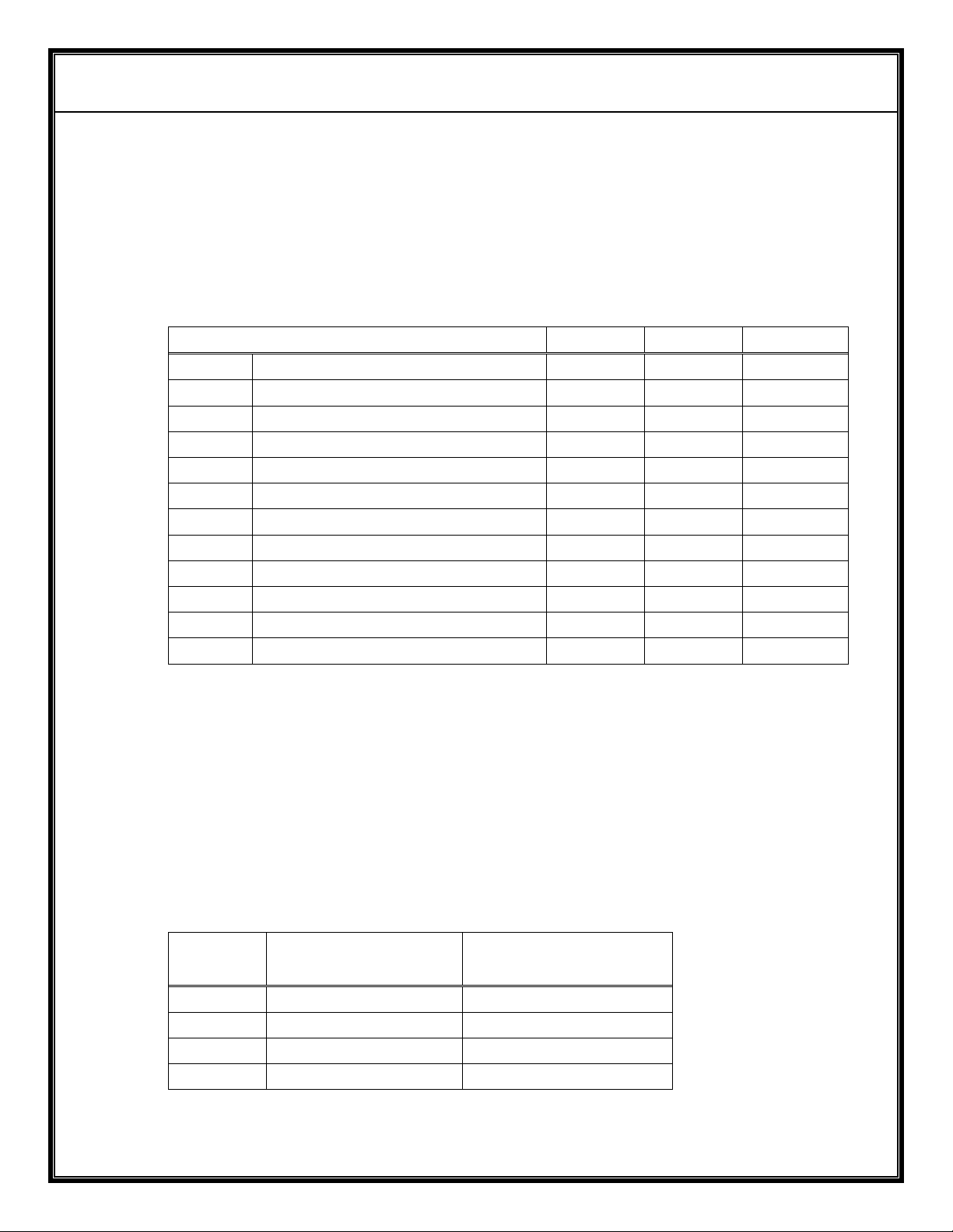
Each receiver requires four (4) antennas. Higher antenna gain yields
longer range with limitations on reception “viewing angle”.
Ordering information:
Description
DX404
DX504
DX604
2dbi omnidirectional
2dbi omni circular polarized
5dbi omnidirectional
6dbi hemispheric patch
9.5dbi panel antenna
10dbi circular polarized(RH) patch
10dbi circular polarized(LH) patch
11dbi log periodic antenna
13dbi panel antenna
15dbi panel antenna
18dbi panel antenna
24dbi parabolic antenna
5.3.2 Antenna cables.
These cables connect the receiver to its antennas. If a system
requires splitters, these cables connect the antennas to the splitters.
DX604: Times Microwave LMR-240 50 Ω (ohm) or equivalent are
AX402
AX405
AX406
AX411
AX502
AX505
AX506
AX513
AX602
AX602R
AX605
AX609
AX610R
AX610L
AX613
AX615
AX618
AX624
recommended for runs up to 30ft and LMR-400 50 Ω (ohm) for runs
from 20ft to 50ft.
Ordering Information:
Length
15’
30’
50’
5’
F-F/75Ω (ohm)
CBLFF-5
CBLFF-15
CBLFF-30
CBLFF-50
N-SMA/50Ω (ohm)
DX404/DX504
DX604
CBLNS-5
CBLNS-15
CBLNS-30
CBLNS-50
Page 24
AVALON RF, INC. Page 21 of 28
DX404/DX504/DX604 User’s Guide & Operating Manual
5.3.3 Antenna cables for the Digital Wireless Link (DWL)
The DWL antenna cable is a BNC to BNC cable with RG58 cable.
5.3.4 Splitters
When a set of four antennas feeds more than one receiver, it is
convenient to split the signal from each antenna to all receivers at the
same location.
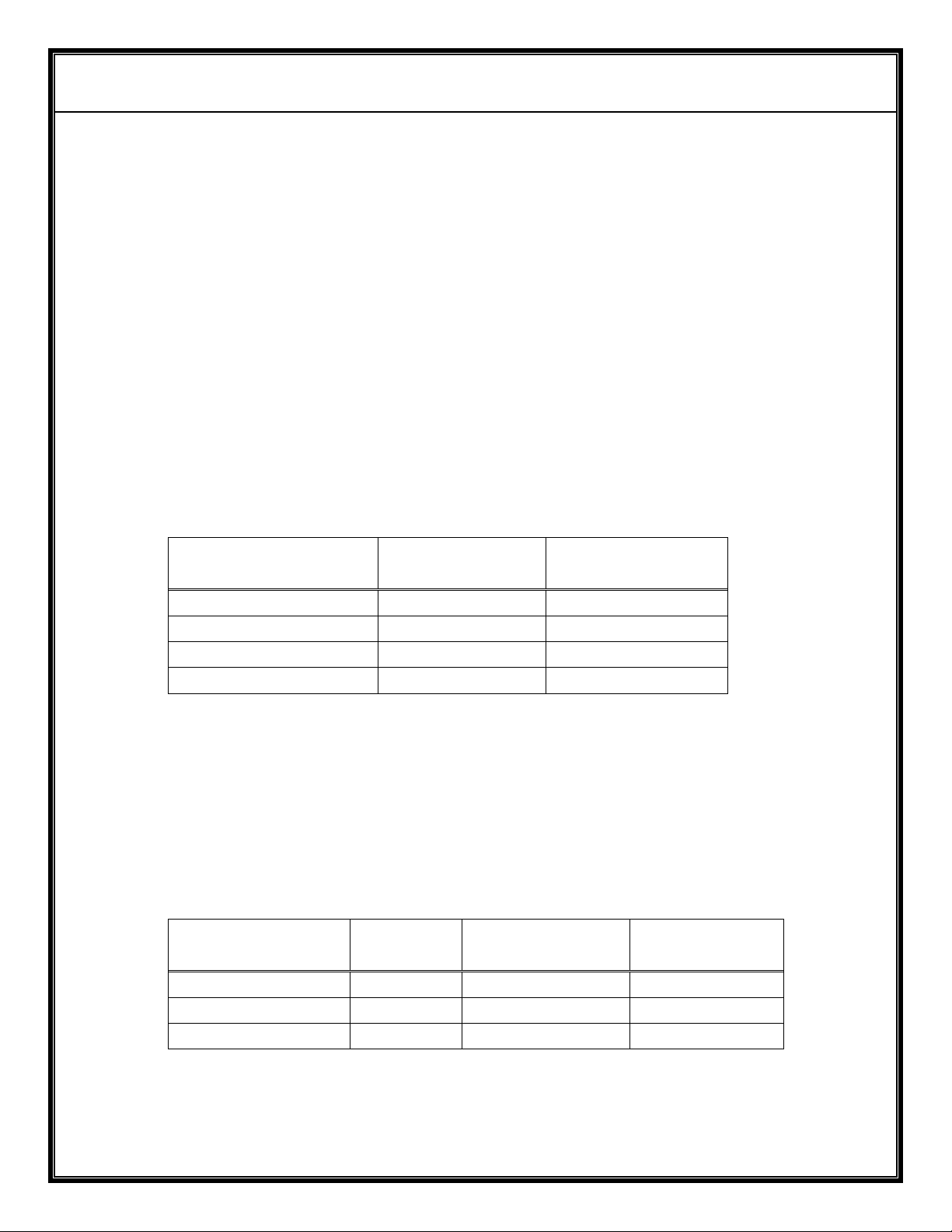
There are two types of splitters: Passive and amplified. Passive are
lower cost and adequate for short range. Amplified splitters are costly
but offer better sensitivity.
Ordering information:
Splitter type
DX404/DX504
(F-F)
DX604
(SMA-SMA)
1 to 2 (two DX..4) SP2F SP2S
1 to 3 (three DX..4) SP3F SP3S
1 to 4 (four DX..4) SP4F SP3S
1 to 8 (eight DX..4) SP8F SP8S
5.3.6 Splitter to receiver cables.
The use of splitters requires jumper cables from every splitter output
to every receiver antenna input. For a four receiver
Ordering information:
Number of DX..4
Receivers
2 8 CBLFF-2 CBLSS-2
3 12 CBLFF-2 CBLSS-2
4 16 CBLFF-2 CBLSS-2
Number
of cables
DX404/DX504 DX604
Page 25
AVALON RF, INC. Page 22 of 28
DX404/DX504/DX604 User’s Guide & Operating Manual
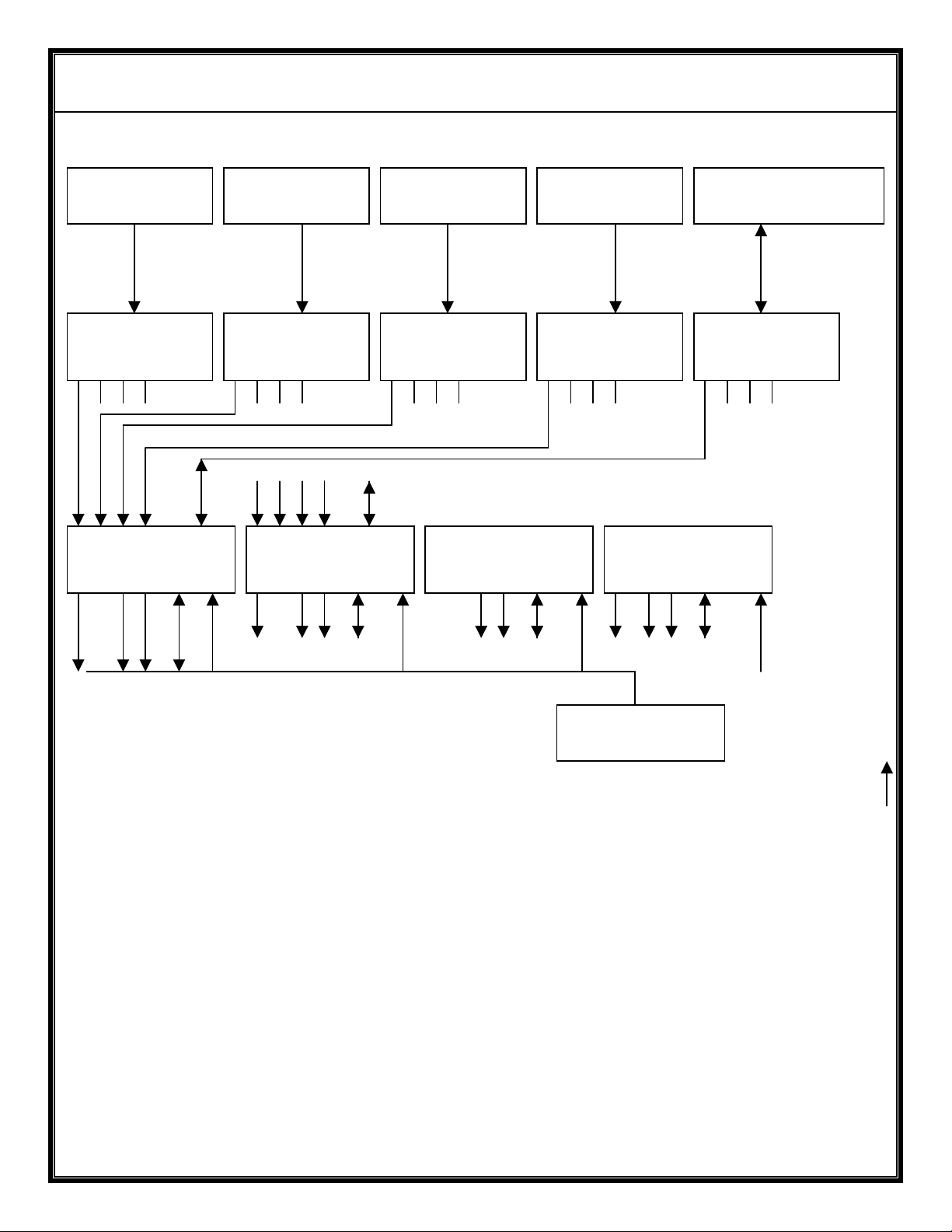
ANTENNA 1
ANTENNA 2
ANTENNA 3
ANTENNA 4
BACK CHANNEL
ANTENNA
ANTENNA
CABLES (4/5)
DX504 or DX604
POWER SUPPLY
110VAC
LOW FREQUENCY
CABLES
VIDEO OUT
(BNC)
AUDIO 1
OUT (XLR3)
AUDIO 2
OUT (XLR3)
DATA
(LEMO 0B-14)
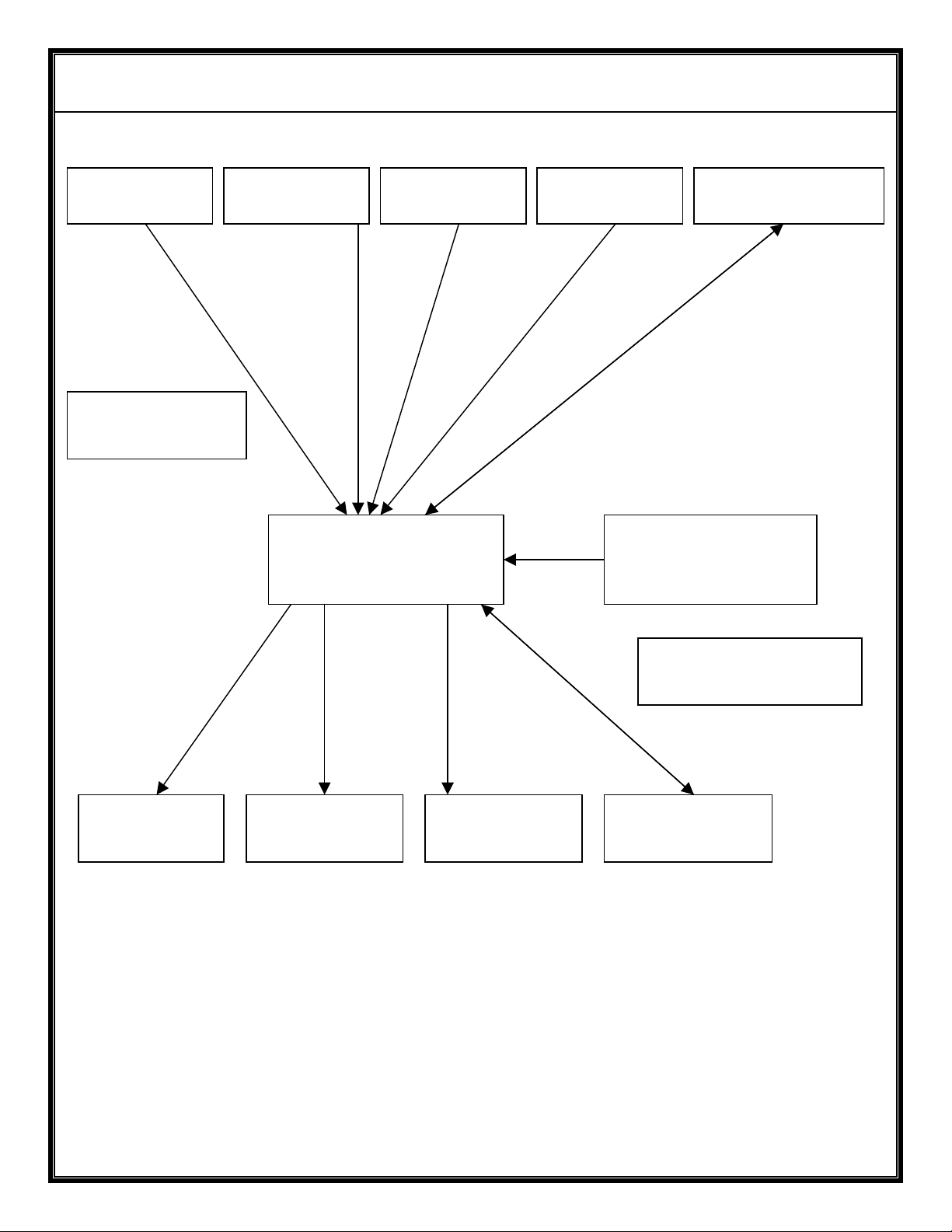
Figure H – Block Diagram of Basic System with a Single
DX404/DX504/DX604 Receiver
Page 26
AVALON RF, INC. Page 23 of 28
V
LINE
DX404/DX504/DX604 User’s Guide & Operating Manual
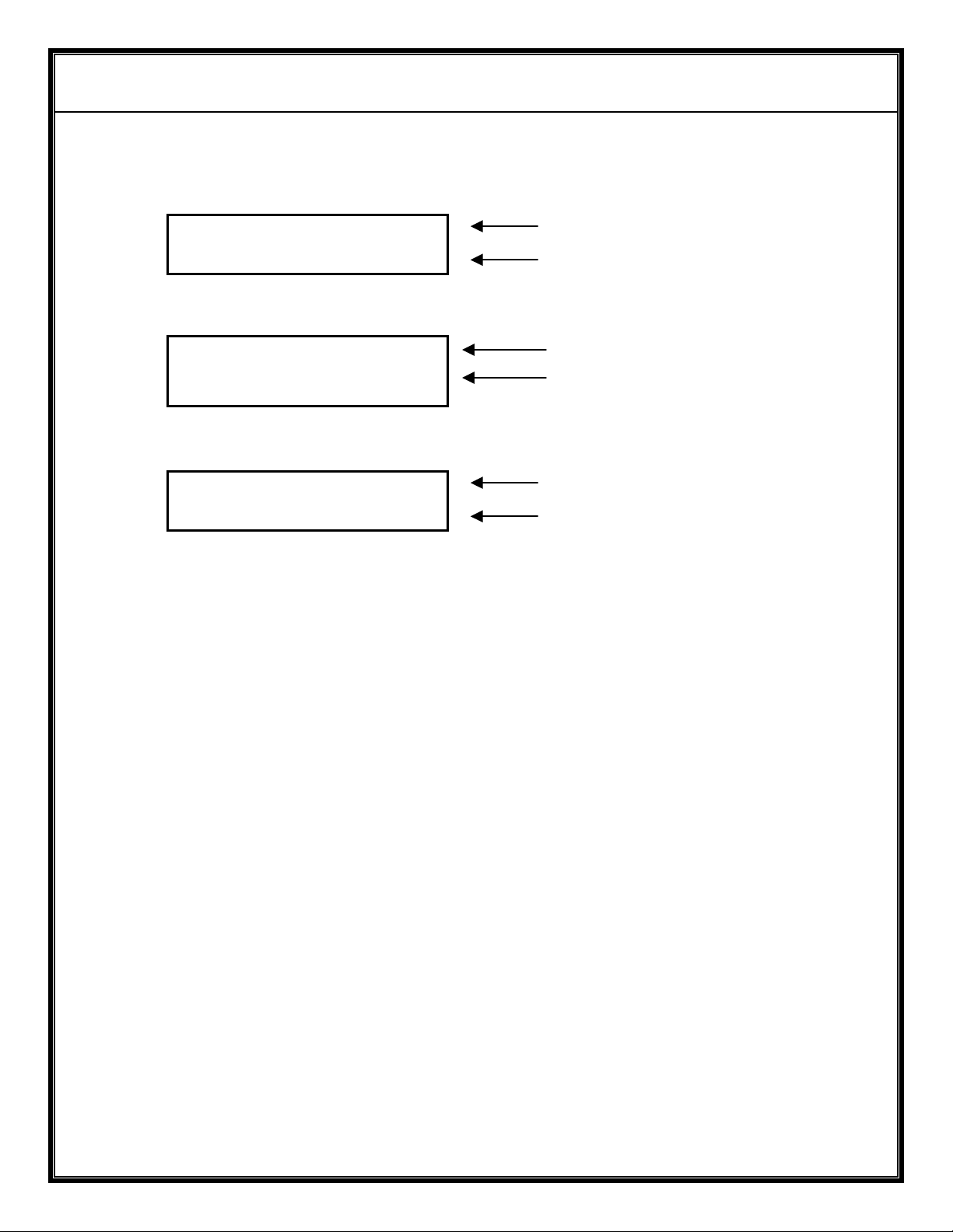
ANTENNA 1
ANTENNA 2
ANTENNA 3
ANTENNA 4
BACK CHANNEL
ANTENNA
ANTENNA
CABLES
4 or 5(*)
CABLES
1:4
SPLITTER
1:4
COMBINER
4:1
SPLITTER
1:4
SPLITTER
1:4
SPLITTER
SPLITTER TO RECEIVER JUMPER CABLES
4 or 5(*) cables per receiver
DX504/DX604
DX504/DX604
DX504/DX604
DX504/DX604
A A D P
4/5(*) CABLES per receiver
(*) With BACK CHANNEL
110VAC
TO 12VDC
Figure J – Block Diagram of System
with
Four DX404/DX504/DX604 Receivers
Page 27
AVALON RF, INC. Page 24 of 28
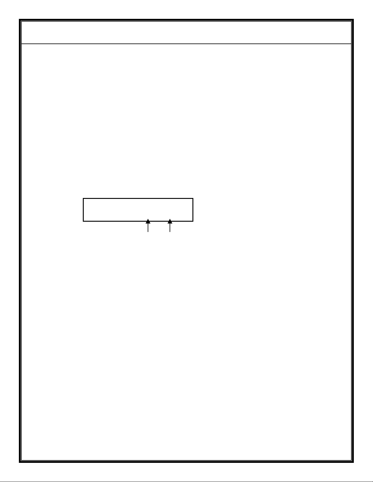
FFFF.FFn aAa bBb
MMMMMMMM NNRAIVL
First line
Second line
FFF.FFMHz SSSS
MMMMMMMM
NNRAIVL
First line
Second line
CH #17 SSSS
MMMMMMMM NNRAIVL
DX404/DX504/DX604 User’s Guide & Operating Manual
Appendix A – LCD format
DX404 LCD format
First line
Second line
DX404 LCD format # 2
DX504/DX604 LCD format
A.1 The format of the first line is:
FFFF.FF is the carrier frequency
SSSS (DX404 only) is the video standard (PAL or NTSC).
n (DX504 only) is the video bandwidth: N = 16MHz
W = 27MHz
aAa (DX504/DX604 only) is the audio1 sub-carrier frequency
bBb (DX504/DX604 only) is the audio2 sub-carrier frequency
Where A and B indicate the sub-carrier bandwidth: N=75KHZ
W=150KHz
Page 28

AVALON RF, INC. Page 25 of 28
DX404/DX504/DX604 User’s Guide & Operating Manual
A.2 The format of the second line is:
MMMMMMMM is a warning prompt: INVALID = wrong entry
BIT = system check
MEM, I2C,KEY
NN is the receiver EIN (For the Optional remote control)
R is a single letter notifying: “P” Program mode, “R” Receive mode
A is a single letter notifying: “A” Automatic mode, “M” Manual mode
I is a single letter notifying: “N” = positive video, “I” negative video
V is a single letter notifying: “V” = video, “R” = video + audio
L is a single letter indicating that the keypad is locked
Page 29
AVALON RF, INC. Page 26 of 28
01
P
ANV
L
DX404/DX504/DX604 User’s Guide & Operating Manual
Appendix B – Remote Programming Option
The DX404/DX504/DX604 can be remotely programmed via a:
• RS232C interface
The data rate is set for 9600 Baud, 8 bits, no parity, 1 stop bit and no
handshaking signals.
B.1 Enabling the remote programming option.
On receipt of a valid command on the serial port, the DX604 enters
the ‘Remote/Programming’ mode and the front panel keypad is
‘locked’. The second line of the front panel LCD will display as
follows:
The P indicating the ‘Remote or Programming’ mode and the L
indicating the locked keypad. To bring the unit back to front panel
operation, the unlock command (*055) can be sent on the serial bus
or use the front panel keypad.
B.2 Commands and responses
Commands sent to the DX604 should be terminated by the “carriage
return” (0Dh) character, the “line feed” (0Ah) character, or the
“carriage return” + “line feed” sequence.
If the command sent is valid, it will be executed and the new content
of the LCD display is sent to the RS232C or IRDT interface,
terminated by a carriage return + line feed. If the command is not
valid, the sequence ‘Error’ is sent back.
Note: When ID is set, prefix all serial commands with the three-byte
EIN sequence. Refer page 16
2407.50N 6W0 6W5
Page 30

AVALON RF, INC. Page 27 of 28
DX404/DX504/DX604 User’s Guide & Operating Manual
B.3 List of Commands
a) Frequency tuning: <FREQ><CR>
b) Channel tuning: #<FREQ><CR>
c) Frequency scanning step size: *92<STEP><CR>
d) Tuner Select: *1# <TN><CR> (1 or more tuners)
e) Turning ON or OFF the display: *#<CR>
f) Unlocking the keypad: *055<CR>
g) Tuning the audio sub-carrier frequencies (DX504/DX604 only):
Audio1: *21# <FREQ><CR>
Audio2: *22# <FREQ><CR>
h) Setting the audio sub-carrier bandwidth:
Audio1: *211<CR> sets Audio1 bandwidth to Narrow.
*210<CR> sets Audio1 bandwidth to Wide.
Audio2: *221<CR> sets Audio2 bandwidth to Narrow.
*220<CR> sets Audio2 bandwidth to Wide.
i) Changing the video bandwidth (DX504 only):
*32<CR> changes the video bandwidth to 27 MHz.
*31<CR> changes the video bandwidth to 16 MHz.
j) Inverting the polarity of the video output:
*42<CR> sets the video output to negative video.
*41<CR> restores video output to positive video.
k) Adding audio sub-carriers to the video output (DX504/DX604 only):
*51<CR> sets the video output to video with no audio.
*52<CR> sets the video output to video with audio.
l) Assigning an EIN (Electronic Identification Number):
*8<EIN><CR> sets the EIN to the 2 digit number between 01 – 99
*8<CR> clears the EIN to 00 (No ID is set)
Page 31

AVALON RF, INC. Page 28 of 28
DX404/DX504/DX604 User’s Guide & Operating Manual
Appendix C – BIT Codes
BIT 0 - memory error (unit is useable but will not retain stored setting)
BIT 1-4 and combinations thereof – the numbers indicate which tuners are
unlocked (the unit needs to be returned to factory for repairs at the
earliest). Partial functionality can be achieved (until unit can be taken out of
service) by removing the unlocked tuner from the diversity temporarily
using the *1 command.
BIT 5 - I2C error. Unit is non-functional & must be sent back for
repairs.
BIT 6/<KEY> - keypad error (a key may be stuck)
 Loading...