

Page 1
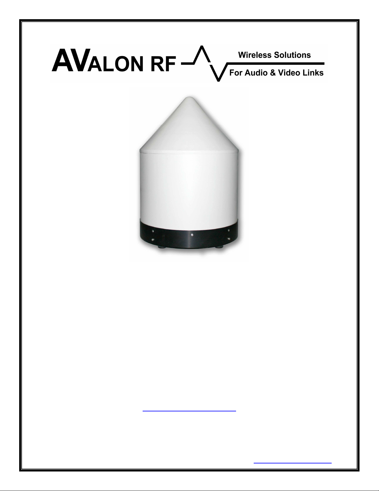
TA-8
Tracking Antenna
User's Guide & Operating Manual
REV. X0 - 21 April 2007
http://www.avalonrf.com/
Avalon RF, Inc. • 344 Coogan Way • El Cajon, CA 92020
Phone: (619) 401-1969 • Fax: (619) 401-1971 • Email: [email protected]
Page 2

AVALON RF, INC. Page ii
TA-8 Series User’s Guide & Operating Manual
Table of Contents
1. General...................................................................................................1
Figure A – TA-8 Series Controls and Connectors .................................3
Radio Reception.....................................................................................4
Video Output ..........................................................................................4
Telemetry Downlink (optional) ...............................................................4
Control Uplink (optional) ........................................................................4
Power.....................................................................................................4
2. Specifications .........................................................................................5
Electrical Specifications.........................................................................5
Interconnecting.......................................................................................6
Figure B – IO Connector pinout.............................................................6
Mounting ................................................................................................8
Mechanical Data ....................................................................................9
Environmental Conditions....................................................................10
3. Operating the TA-8...............................................................................11
General Guidelines ..............................................................................12
4. Error Conditions ...................................................................................12
5. Ordering information ............................................................................13
Base models ........................................................................................13
Options.................................................................................................13
Recommended Accessories................................................................14
Page 3

AVALON RF, INC. Page 1
TA-8 Series User’s Guide & Operating Manual
1. General
The TA-8 Tracking Antenna is intended for use in military, homeland
security, mobile security etc. for reception of wireless video from a
moving source (e.g a UAV/ Helicopter). The unit is completely self
contained and requires no setup or connections of antennas, cables
etc. All necessary cables have been supplied to setup the link within
a few minutes.
The TA-8 features a unique patented design that allows for excellent
reception of wireless video from within any hemispherical location of
the moving transmitter. The TA-8 does not have any moving parts,
which facilitates its usage in harsh weather including dusty/ saline/ icy
environments. The absence of moving parts allows permanent
installation on roof tops/ high rise buildings and is also suitable for
mobile operations. The operating distance (radius of the
hemispherical pattern) depends on a variety on factors such as
transmit antenna gain, transmitter power etc.
There are 3 versions of the TA-8:
a) TA-8 (standard) : Video and Audio reception
b) TA-8-C1 (UAV model): Video and Telemetry downlink data at
4.8Kb/s
c) TA-8-C2 (UAV model): Video, Telemetry downlink and Control
Uplink
All 3 models offer the following features:
• A single high quality video channel with no delay.
• Complete operator free reception from any hemispherical direction
Optional features (each ordered individually).
• Telemetry down Link.
• Control Uplink.
Any reference in this manual to TA-8 implies all 3 models.
Page 4
AVALON RF, INC. Page 2
TA-8 Series User’s Guide & Operating Manual
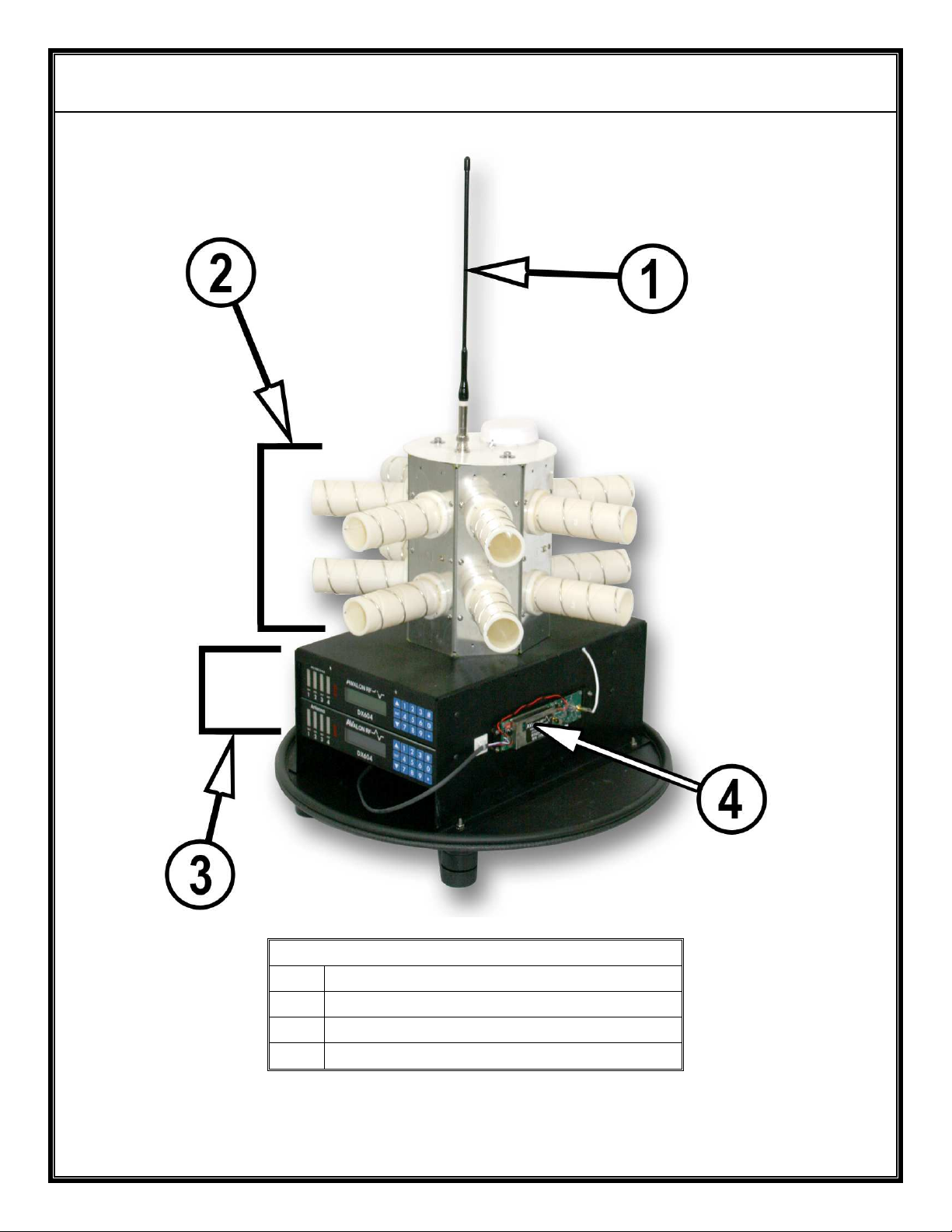
Side View
1 Control Uplink Antenna (UHF)
2 Antenna Array
3 DX604 Receivers
4 Control Uplink Module
Figure A – TA-8 Series Controls and Connectors
Page 5
AVALON RF, INC. Page 3
TA-8 Series User’s Guide & Operating Manual
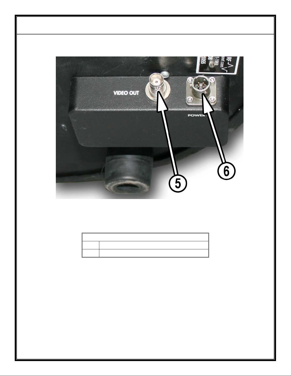
Bottom View
5 Video Output
6 Power & I/O Connector
Figure B – TA-8 Series Controls and Connectors
Page 6

AVALON RF, INC. Page 4
TA-8 Series User’s Guide & Operating Manual
1.1 Radio Reception.
The TA-8 has 8 antennas configured in a flower like arrangement. 7
antennas cover the 360o azimuth while an 8th antenna looks straight
up. This gives complete reception within the hemisphere. The user
does not have to make any antenna connections. The TA-8 is tuned
to receive a rf channel by tuning the two DX604’s.
1.2 Video Output.
The intelligent electronics in the TA-8, does diversity both on the rf
signal and then on the video. The final output is available dc restored
to ground and continuously corrected for optimum level (1V p-p).
1.3 Telemetry Downlink (optional).
With this option, the audio sub-carrier on the rf signal is configured to
receive digital data at 4.8Kb/s. This received digital information is
then processed for timing recovery and made available at RS232
levels for direct connection to a serial port of a pc.
1.4 Control Uplink (optional).
This option adds a uplink radio link which works on UHF frequencies.
A separate omni directional antenna is installed inside the TA-8 for
communication with a companion receiver on the airplane. This link
accepts RS232 level input at 4.8Kb/s and transmits the data
wirelessly with error correction for perfect reception.
The combination of this link and the telemetry downlink option gives a
full duplex data communication with the bird (UAV/ Helicopter).
1.5 Power.
The TA-8 works off a standard 12V power source. The load is approx
3A or less. Avalon RF has supplied a universal input 100-240V, 5060Hz power supply that is recommended to be used with this unit. If
the user plans to use their own power supply (such as Vehicle
operation), please ensure that the power supply is capable of at least
7-8A to allow for the turn-on current surge.
Page 7

AVALON RF, INC. Page 5
TA-8 Series User’s Guide & Operating Manual
2. Specifications
2.1 Electrical Specifications.
Frequency Range: 2400 – 2483 MHz (standard)
2150 – 2500 MHz (extended – Option 4)
Tuning: Individual tuning via front panel of 2 x DX604’s;
Tuning resolution: 250 KHz
RF Sensitivity: typ better than - 84 dBm
Bandwidth: 27 MHz
Antennas: 7 x 15 dBic RHCP helical antennas to cover 360
azimuth
1 x 6 dBic RHCP patch antenna for over head
coverage
Video Output: NTSC or PAL (depending on system ordered)
Video level: 1 Vp-p into 75 ohm, Negative Sync Tip, dc restored
to ground.
Telemetry Downlink (optional)
Telemetry output: RS232 compatible signal levels with 8 data bits, No
Parity, 1 stop bit
Baud Rate: 4800 Baud
Control Uplink (optional)
Frequency Range: 392-420 MHz standard; any 40 MHz band in the
frequency range 350 MHz – 800 MHz possible
No of Channels: 16 through 4 DIP switches
RF Impedance: 50 ohm
RF Output: 1W
Antenna: Half wave Omni directional (2.2 dBi gain); mounted
inside dome
Data Input: RS232 compatible signal with 8 data bits, No Parity,
1 stop bit
Data Rate: 4800 Baud
o
Page 8
AVALON RF, INC. Page 6
TA-8 Series User’s Guide & Operating Manual
Power: 12V unregulated DC nominal; 10.5 -17V DC input
Consumption: < 3A
2.2 Interconnecting.
All input/ output connections to the TA-8 are available through the
BNC and the 8 pin connector on the IO box on the bottom of the unit.
Video output is through the BNC (f) connector labeled VIDEO.
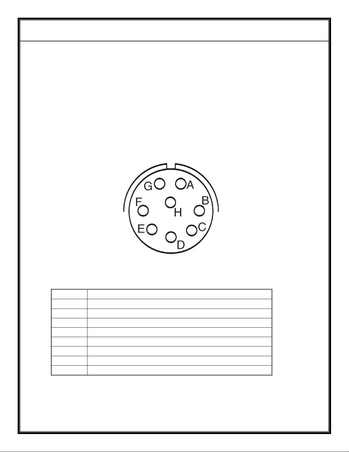
The pin out of the 8 pin connector is as shown in figure C.
Figure C – IO Connector pinout
Pin # Function
A Power Input (+12Vdc Nominal)
B Power Return (Ground)
C Control Uplink Ground
D Control Uplink Data (RS232)
E Telemetry Downlink Ground
F Telemetry Downlink Data (RS232)
G Reserved
H Reserved
Page 9

AVALON RF, INC. Page 7
TA-8 Series User’s Guide & Operating Manual
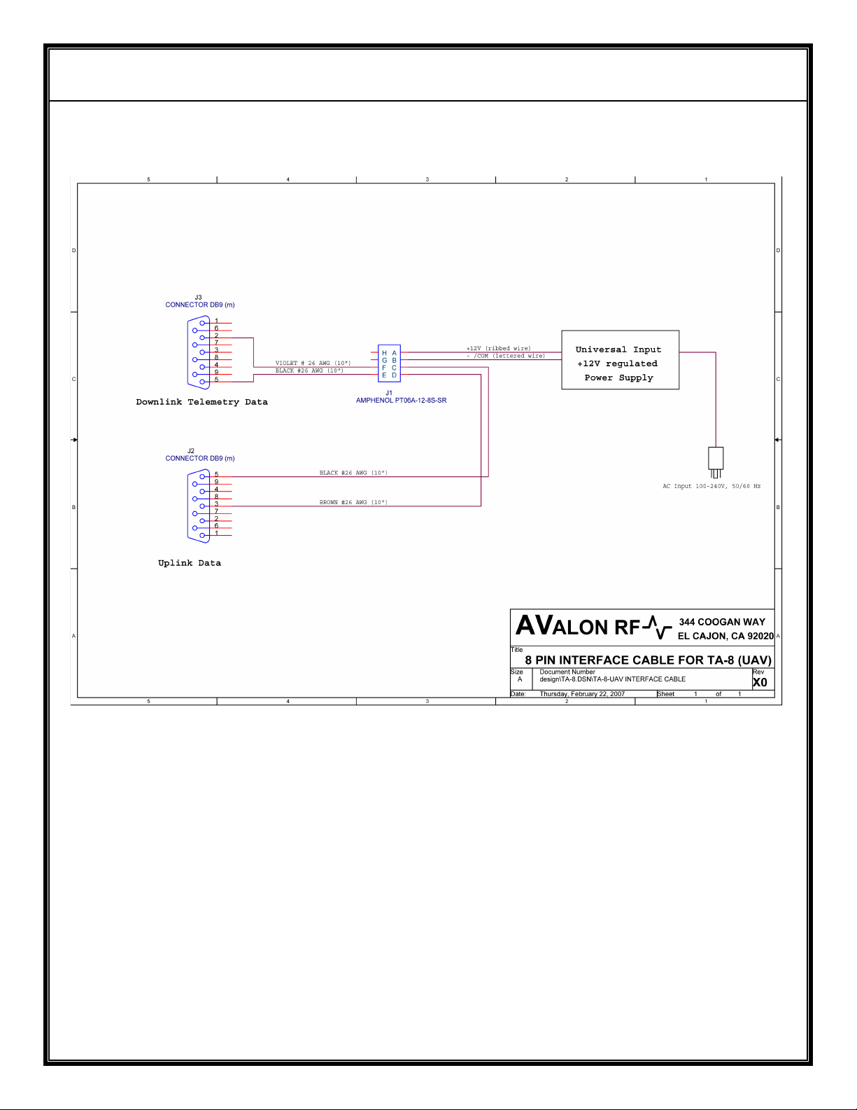
Avalon RF has supplied a 8 pin cable that breaks out into separate
connections for power, telemetry and control uplink (if ordered). The
telemetry downlink and the Control uplink connectors are standard 9 pin Dtype connectors that interface directly to the serial COM port of a PC.
Page 10

AVALON RF, INC. Page 8
TA-8 Series User’s Guide & Operating Manual
2.5 Mechanical
2.5.1 Mounting/ Installation.
The TA-8 is shipped in a transit case and has room to accommodate
all cables and power supplies. The radome of the TA-8 is designed to
prevent formation of ice and is thus suitable for all climatic conditions.
For mobile applications the TA-8 should be placed as high as is
practically possible to maximize the operating range/ distance.
Ensure that the TA-8 is placed on a horizontal surface that does not
have any transmitters in the immediate vicinity of the chosen location
for the TA-8. It can be placed on the roof of a Humvee or truck
although a higher location will improve operating range.
For fixed installations, a mounting plate can be used to mount the TA-
8 on top of a pole or similar structure.
Page 11
AVALON RF, INC. Page 9
TA-8 Series User’s Guide & Operating Manual
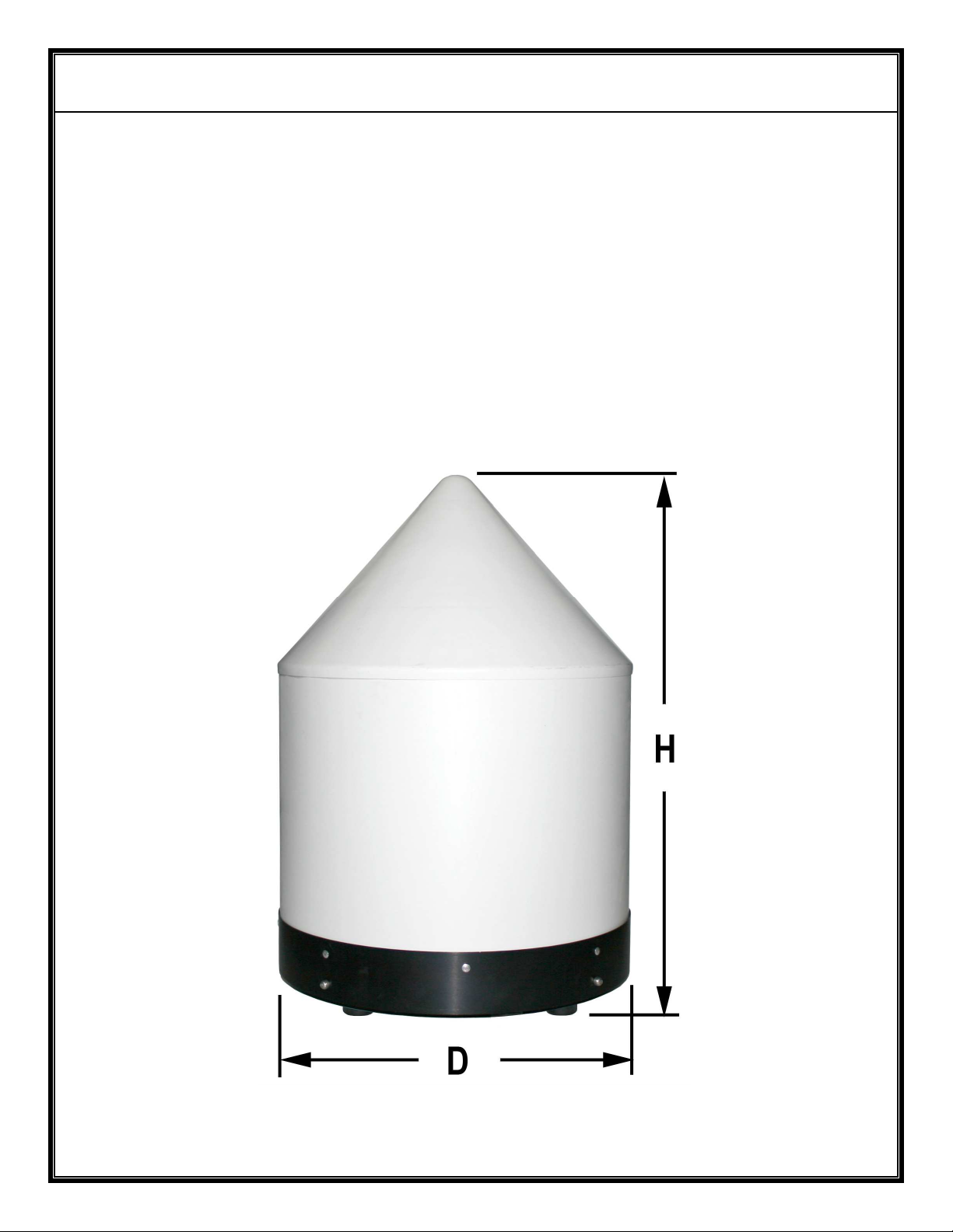
2.5.2 Mechanical Data.
a) Size (see Figure G) D = approx. 19 in (48 cm)
H = approx. 27 in (69 cm) for TA-8 & TA-8-C1
H = approx. 31 in (79 cm) for TA-8-C2
b) Weight approx. 28 lbs (12.7 Kg) for TA-8 & TA-8-C1
approx. 32 lbs (14.5 Kg) for TA-8-C2
c) Shipping weight <
<
Figure G – TA-8 Series Mechanical Outline
Page 12

AVALON RF, INC. Page 10
TA-8 Series User’s Guide & Operating Manual
2.6 Environmental Conditions.
The TA-8 Series is designed to meet the following environmental
conditions:
2.6.1 Operating temperature -4° to 122° F
-20° to 50° C
2.6.2 Storage temperature -13° to 150° F
-25° to 65° C
2.6.3 Humidity 5 to 95%, non-condensing
2.6.4 Inclination Any
2.6.5 Altitude -1500 feet to 15,000 feet
-450 meter to 4,500 meters
Page 13

AVALON RF, INC. Page 11
TA-8 Series User’s Guide & Operating Manual
3. Operating the TA-8.
All required antenna connections have been made before shipping
the TA-8. Please do not disconnect any antenna at any time.
NOTE
The TA-8 requires a radio line of sight (LOS) to work correctly. It
may be used in other non-LOS situations but the operating
distance could be significantly reduced.
3.1 The only operator control is the frequency setting on each DX604.
Please DO NOT refer to the DX604 manual and attempt to
configure the DX604’s differently. Doing so could result in the
TA-8 becoming non-functional.
The following command sets the frequency of a DX604:
<FREQ> <ENTER> tunes in to the desired frequency. The <*> key is
used as a decimal point.
The DX604 tuning range is from 2400 MHz to 2483 MHz (2150 to
2500 MHz with Option 4).
E.G.:
2412<ENTER> tunes a DX604 to 2.412GHz.
The tuned-in frequency appears on the top left of the LCD.
If <FREQ> is out of the tuning range, the receiver will display
“INVALID” and default to the last valid tuned-in frequency.
E.G.:
912<ENTER> is beyond the tuning range of the DX604 and will be
rejected.
If the frequency is valid, it is saved even when power is turned off. If
the display and the bargraph’s are blinking, it is an indication that the
input voltage is below 10.5V. In this case, to prevent corrupted data
being stored, any new setting of the DX604 will NOT be saved. The
last setting made when power was good will be retained.
Page 14

AVALON RF, INC. Page 12
TA-8 Series User’s Guide & Operating Manual
To prevent unauthorized/accidental change of the receive frequency/
channel, the keypad can be locked.
*077 <ENTER> locks the keypad.
*055 <ENTER> unlocks the keypad.
The LCD displays a “L” at the bottom right if the keypad is locked.
3.2 General Guidelines
While the setup of the TA-8 link is very simple, observing a few
considerations will help get the optimum performance.
First, height of the equipment plays an important role in the distance
over which the radio link works. The higher you place the TA-8, the
longer the available link range. Please use proper judgment of safety
when following this advice, especially for mobile applications.
For any rf signal, having metal objects near the receiving or
transmitting antenna will severely affect the performance. With this in
mind, avoid placement in any location that has large metal structures
or objects that hinder a good LOS to the transmitter. The TA-8 being
a microwave receiver, trees and buildings are also an obstruction to
signal reception.
The radio link must be configured correctly and the equipment
chosen to meet the required range/ distance. Choice of transmitter
amplifier, output power, type of antenna etc. is governed by
considerations such as battery power on the UAV/ airplane, antenna
height allowed, cooling for transmitter etc. If you need assistance,
please call Avalon RF Engineering at 619-401-1967.
4. Error Conditions
T.B.D.
Page 15

AVALON RF, INC. Page 13
TA-8 Series User’s Guide & Operating Manual
5. Ordering information
5.1 Base models
TA-8 Standard TA-8
TA-8-C1 TA-8 with Telemetry downlink
TA-8-C2 TA-8 with Telemetry downlink and Control Uplink
All units come with the following standard accessories:
5.1.1 A heavy-duty carrying case
5.1.2 Universal input (100 – 240V, 50-60 Hz) AC power adaptor.
5.1.3 User guide & operating manual (this manual).
Additional accessory supplied with TA-8-C1 and TA-8-C2:
5.1.4 Interface cable for connection of data IO.
5.2 Options.
5.2.1 Option 00 – European version (PAL).
5.2.2 Option 04 – Extended tuning range
TX600 series – 2.150GHz to 2.5GHz
Page 16

AVALON RF, INC. Page 14
TA-8 Series User’s Guide & Operating Manual
5.3 Recommended accessories.
5.3.1 Additional power (power/ data IO) cable for mobile applications
Page 17
AVALON RF, INC. Page 15
TA-8 Series User’s Guide & Operating Manual
Appendix A
 Loading...