

Avalon RF ODX402, ODX502, ODX602 User's Manual & Operating Manual

ODX402 / ODX502 / ODX602
COFDM Digital Video Diversity
Receiver
User's Guide & Operating Manual
REV. B
Avalon RF, Inc. • 344 Coogan Way • El Cajon, CA 92020
Phone: (619) 401-1969 • Fax: (619) 401-1971 • Email: sales@avalonrf.com
02 Feb 2009
http://www.avalonrf.com/

AVALON RF, INC. Page ii
ODX402/ ODX502/ OODX602 User’s Guide & Operating Manual
Table of Contents
1. General................................................................................................1
Figure A – Front Panel.........................................................................2
Figure B – Rear Panel..........................................................................3
2. Specifications.......................................................................................4
Frequency Range................................................................................4
Power Input .........................................................................................4
Figure C – Power Input ....................................................................4
Antenna Inputs ....................................................................................5
Video Outputs......................................................................................5
Audio Outputs......................................................................................5
Figure D – Audio Output(s) ..............................................................5
Data/Program Output...........................................................................6
Figure E –Data/Program Output.......................................................6
Digital Wireless Link Antenna Output...................................................6
WDL Interface......................................................................................7
Figure F – WDL Interface.................................................................7
WDL Power Input.................................................................................7
Serial RS232 I/O..................................................................................7
Size .....................................................................................................8
Weight.................................................................................................8
Mounting Methods...............................................................................8
Figure G – ODX602 Mechanical Specifications - Inches [mm].............9
Figure H – ODX602 Mounting Holes..................................................10
Environmental Conditions..................................................................11
3. Operating Instructions........................................................................12
Human Interface................................................................................12
Front Panel Channel Select Switches ............................................12
Front Panel Indicators....................................................................12
OSD Menu Control.........................................................................12
Power On/ Off ................................................................................13
Operating the ODX602 ......................................................................13
4. Ordering Information..........................................................................15
Optional features............................................................................15

AVALON RF, INC. Page 1 of 15
ODX402/ ODX502/ OODX602 User’s Guide & Operating Manual
1. General
The ODX402/ ODX502/ OODX602 receiver is a new introduction to
the Avalon digital video family. It is a rugged 2-antenna diversity
receiver using maximal ratio combining to mitigate fading & multipath
effects. The receiver is ideal for demanding high-end video
applications that require robust video. The low power consumption &
the quick switching between 16 channels gives added convenience in
handheld & or body worn applications.
Features like OSD menu, two video outputs & front or rear antenna
inputs enhance suitability of the ODX602 to various applications.
The ODX402 is a VHF/ UHF receiver, the ODX502 is a L-band
receiver and the ODX602 is a S-band receiver.
NOTE
Unless explicitly stated, every reference in this document to
the ODX602 also implies the ODX402 and ODX502. The
main difference between the models is the frequency
range.
The ODX602 receiver has the following standard channels:
A video channel.
An audio channel.
A data channel for telemetry data.
Optional features include:
• Wide version (- W) to accommodate a Avalon Transceiver
TR430-2G for high speed 115Kbps data or TR423 for 9.6Kbps
• Data transceiver (Opt 11) – installs a TR423 transceiver
• Talk back audio channel (Option 31)
• Rack Mount Kit (Option R2)
AVALON RF, INC. Page 2 of 15
ODX402/ ODX502/ OODX602 User’s Guide & Operating Manual
2 3 8
1
4 5 6 7
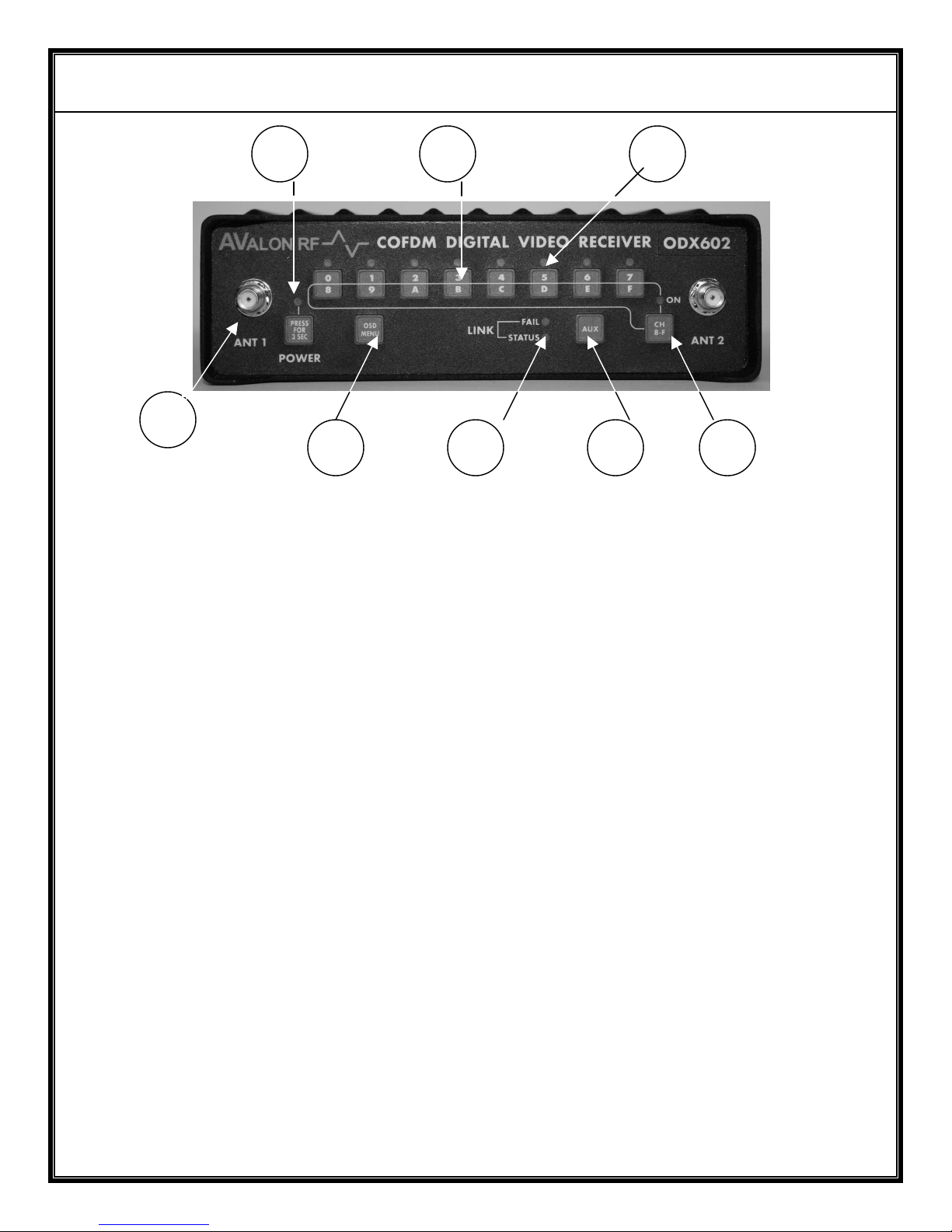
Figure A – Front Panel
ODX402/ODX502/ODX602 Controls, Indicators and Connectors
1 - Antenna 1 Input
2 - Power Indicator LED
3 - Channel Select Switches
4 - OSD Menu Switch
5 - Link Indicators
6 - AUX switch (Reserved)
7 - Bank select switch
8 - Channel Indicator led’s
AVALON RF, INC. Page 3 of 15
ODX402/ ODX502/ OODX602 User’s Guide & Operating Manual
1 3
4 2 5
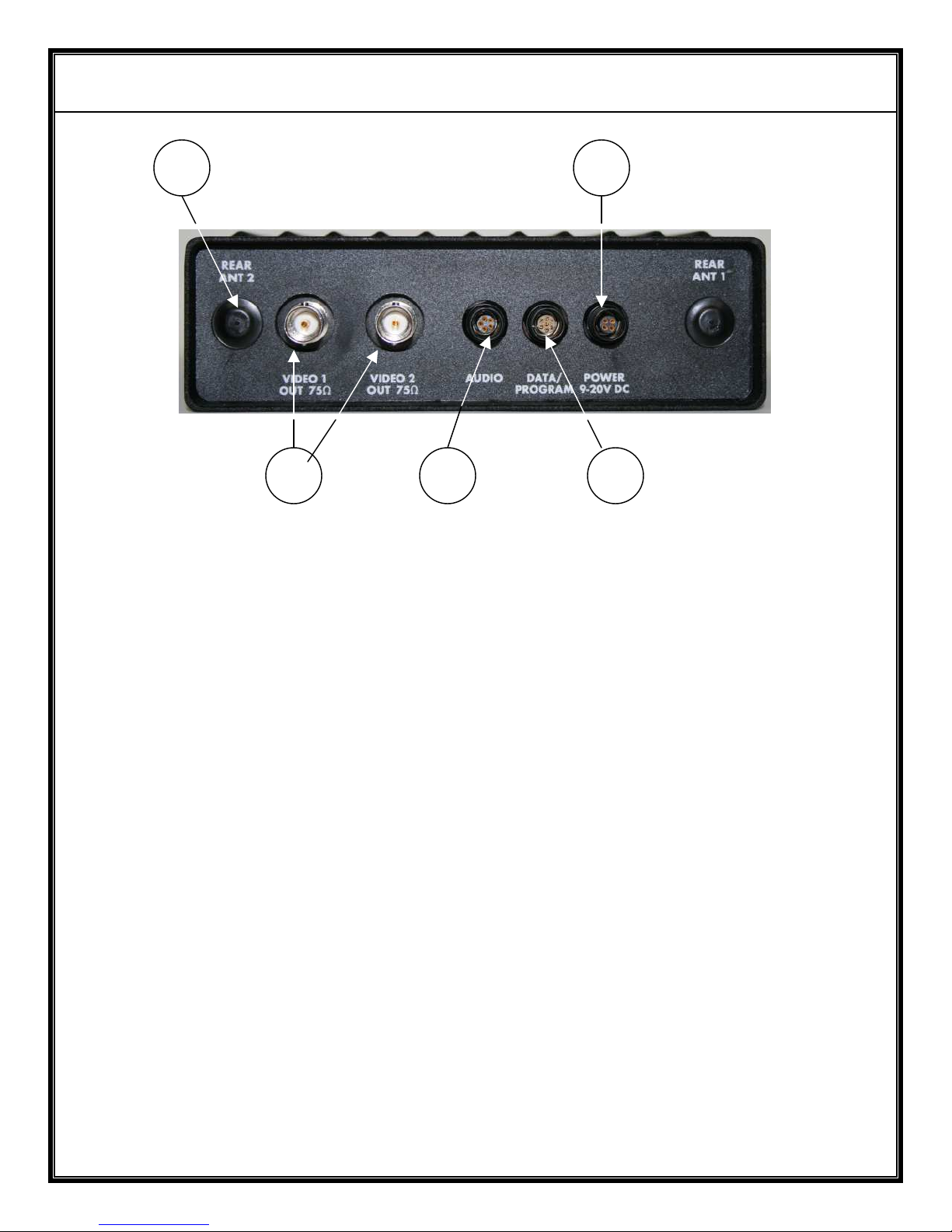
Figure B – Rear Panel
ODX402/ODX502/ODX602 Controls and Connectors
1 Rear Antenna inputs
2 Audio Output Connector
3 Power Connector
4 Video Outputs
5 Data Output/Program
Connector
AVALON RF, INC. Page 4 of 15
ODX402/ ODX502/ OODX602 User’s Guide & Operating Manual
2. Specifications
2.1 Frequency Range (Model Dependent).
The frequency range of each model has a base number that identifies
its band. E.g 4 is UHF, 5 is L-band & so on. The ‘standard’ frequency
ranges for the various models are as follows:
ODX402: UHF receiver with a tuning range of 170-230 MHz or
470MHz-862MHz.
ODX502: L-band receiver with a tuning range of 900 MHz-1200 MHz
or 1.2GHz-1.8GHz.
ODX602: S-band receiver with a tuning range of 2.1GHz-2.5GHz or
2.3 –2.7 GHz.
There can be 16 channels within the operating range. For frequency
ranges other than those indicated, please contact Avalon RF sales.
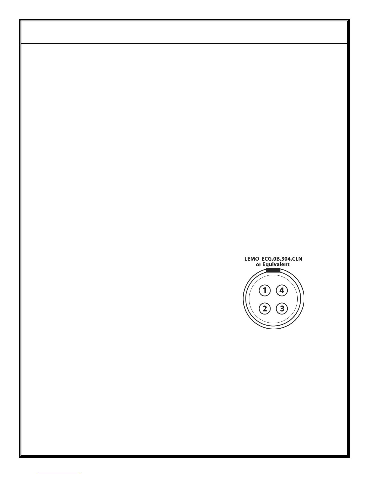
2.2 Power Input – (Circle 3 on rear panel).
a) The power input connector is a 4 pin on the rear panel of the
ODX602.
Pin 1 – Power Return
Pin 2 – NC
Pin 3 – NC
Pin 4 – Power Input (+9Vdc to +20Vdc)
Figure C – Power Input
b) The ODX602 operates off a 9Vdc to 20Vdc unregulated voltage
source with a ripple of less than 0.5Vp.p.
c) Input Current is <0.6 Amps at an input voltage of 12Vdc.
d) Power is switched ON/OFF via a front panel electronic switch.
e) The ODX602 power input is protected against reverse polarity and
also has a under voltage lock-out.
 Loading...