


THIS PRODUCT IS DESIGNED FOR PROFESSIONAL INSTALLATION
Oct/23/2006
MODEL MA-200
2-WAY REMOTE CONTROL MOTORCYCLE ALARM
OPERATION INSTRUCTIONS
OPERATION MANUAL
Please register your product at:
www.autopageusa.com
MA-200 OP REV.A 1

Oct/23/2006
TABLE OF CONTENTS:
A. REMOTE TRANSMITTER OPERATION ……………………………………….…………………….………...3
B. 2-WAY LCD REMOTE CONTROL TRANSCEIVER OPERATION ONLY.………..…………………..…... 3
C. LED DISPLAY .……………..……………………………………………………………………….……………. 3
D. CHIRP INDICATOR ..………..……………………………………………………………………………..……. 4
E. PARKING LIGHTS …….……..…………………………………………………………………………..….….…. 4
F. ALARM OPERATION CONDITION .………………………………………………………………………….… 4
G. ACTIVE ARMING – ARM & LOCK .……………………………………………………………………….…… 4
Silent Arming
Arming in Silent Mode
Arming with Shock Sensor By-Pass
Passive Start Disable
Arming with Pathway Illumination
Arming with Hidden Alarm Function
H. PASSIVE ARMING – …….………….…………………………………………………………………………… 4
Passive Arming By-Pass
I. ACTIVE DISARMING .…………………………..……………………………………………………..……….…. 4
Clearing the Flashing Icons
Silent Disarming
Tamper Disarming
Pathway Illumination
Automatic Re-Arm
J. DISARMING WITHOUT A TRANSMITTER .……………..…………………………………………………… 5
Overrides the Alarm without Password Pin Code
Overrides the Alarm with Password Pin Code
K. VALET MODE .……………..……………………………………………………………………….……….…… 5
Enter Valet Mode
Exit Valet Mode
Remote Valet
L. CAR LOCATOR .……………………………………………………………………….……………………….… 6
M. PANIC FUNCTION .………………………………………………………………………………...……………. 6
N. TRIGGER THE SYSTEM .………………………………………..…………………………..……….……….… 6
Clearing the Flashing Icons and Melody Sound
Clearing the Melody Sound Only
Noise Abatement Circuit
O. SYSTEM’S TRIGGER CHECK ………………………………………………………………….….…....…….. 6
P. DRIVER PAGING / LOST AND FOUND……………………….…………..…………………………..……… 7
Q. CHANNEL 3 TIMER CONTROL OUTPUT ………………………….………………………………….…….. 7
R. CHANNEL 4 TIMER CONTROL OUTPUT ………..………………………………………………....…..…... 7
S. POWER ON MEMONRY: ………..…………………………………………………………………..….….…… 7
T. POWER SAVE MODE FOR MOTORCYCLE’S POWER:………………………………………..….….…… 7
U. FORGOTTEN BLINKER (left or right indicator): …………….…….………………..….….……………… 7
LCD REMOTE TRANSCEIVER:
A. BATTERY REPLACEMENT ……………………………….………………………………………………..….. 7
B. THE REMOTE LCD ICONS WITH FUNCTION ……….…………………………………………………...…. 7
C. PROGRAMMING OF THE LCD REMOTE TRANSCEIVER ………………………………….…………..… 8
1. Screen Lamp ON.
2. Power Save Mode For Remote Transceiver
3. Clearing the Flashing Icons and Melody Sound
4. Stop The Melody Sound.
5. Button Lock
MA-200 OP REV.A 2
Oct/23/2006
Press and release momentarily
-
-
F
+
Press and release momentarily
F
+
Press and release momentarily
-
-
6. Vibration / Melody Mode
7. Enable / Disable Bi Sound While Pressing Button:
8. Low Battery Indication.
9. Set Up Fixed Count Down Timer
10. Out Of Range Check
D. TIMER SETTING ……………………………….………………………..…………………….…………….… 9
1. Timer Setting.
2. Alert Alarm Timer Setting
3. Count Down Timer Setting
OPERATION:
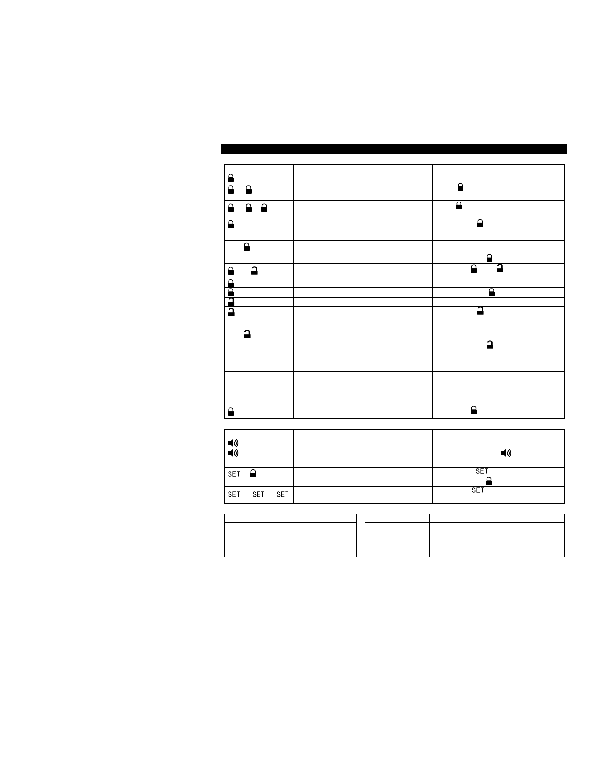
A. TRANSMITTER OPERATION:
Transmitter Button System Function Remark
-
- F
F -
(3 seconds)
- F
F -
F - F
F - F - F
(2 seconds)
F (2 seconds)
Arm the System
Arming with Noiseless Mode
Arming with Shock Sensor Bypass
Arming with Pathway Illumination
Silent Arm
Arming with Hidden Alarm
Motorcycle Locator Upon armed
Panic
Disarm System
Disarming with Pathway Illumination
Silent Disarm
Passive Arming By-pass
Remote control Enter/Exit Valet mode
Channel # 3 Timer Output Press and Hold for 2 seconds
Channel # 4 Timer Output
Press button within 3 seconds after
arming.
Press button 2 times within 5 seconds
after arming
Press the
seconds press
Press the F button first within 3
seconds press
Press the
Press and Hold button for 3 seconds
Press the
seconds press F
Press the F button first within 3
seconds press
Upon disarmed, press the F button
twice within 3 seconds.
Press the F button 3 times within 5
seconds.
Press the and F buttons together
button first within 3
and buttons together
button first within 3
B. FOR 2-WAY LCD TRANSCEIVER OPERATION ONLY:
Transceiver Button System Function Remark
(3-second)
-
Motorcycle Locator
Panic function
System’s Trigger Check Press the button first within 3
Clear the Flash Icon and Melody Sound
on the LCD Screen Transmitter
Press and Hold button for 3
seconds
seconds press
Press the button 3 times within 5
seconds.
C. LED INDICATORS:
LED Function LED Function
Off Disarmed 2 flashes... pause Zone 2 / Activated on the Tilt Switch
Slow Flash Armed 3 flashes... pause Zone 3 / Activated on the Close Loop
Flash Passive Start Disable 4 flashes... pause Zone 4 / Activated on the Shock Sensor
Fast Flash Passive Arming 5 flashes... pause Zone 5 / Activated on the Ignition Switch
MA-200 OP REV.A 3
Oct/23/2006
will flash once indicating the system is
button on the
rm
On (Solid) Valet Mode
D. CHIRP INDICATORS: E. PARKING LIGHTS:
Chirp Function Parking lights Function
1 chirp Arm 1 flash Arm
2 chirps Disarm 2 flashes Disarm
4 chirps Disarm / Triggered 3 flashes Disarm / Triggered
6 chirps Car locator 12 flashes Car locator
F. SYSTEM OPERATING CONDITION:
Siren, Horn Parking Lights LED Starter
1. Arming 1 Chirp 1 Flash Slow Flash Disable
2. Disarming 2 or 4 Chirps 2 or 3 Flashes Fast Flash or Off
3. Trigger Alarming Flashes Slow Flash Disable
4. Passive Starter Disable Flash Disable
5. Panic Alarming Flashes
6. Car Locator 6 Chirps 12 Flashes
G. ACTIVE ARMING :
1. Press the button on transmitter.
2. The siren will chirp once and the parking lights
armed. The LED will begin to flash and the engine starter will be disabled.
SILENT ARMING: Press the F button first, within 3 seconds press
transmitter to arm your security system, No chirp sound will be heard. A
confirmation will be through the motorcycles parking lights only.
ARMING WITH NOISELESS MODE: With the system disarmed, press the button once, the siren will
chirp once. Within 3 seconds, press button again. The siren will emit one short chirp indicating the
system is set and will be fully armed in 5 seconds with the noiseless mode for one arming cycle. In this
mode, whenever vibration is presented to the protected motorcycle, the shock sensor cannot trigger the
system and the system will only emit a few warn away chirps.
ARMING WITH SHOCK SENSOR BY-PASS: Pressing the button on the transmitter three times within
5 seconds will arm the security system and by-pass the shock sensor. The system will chirp one additional
time to confirm the sensor bypass mode was activated. The sensor bypass feature is programmed to
activate for one arming cycle only. The security system will return to normal operation during the next
arming cycle.
PASSIVE STARTER DISABLES: The purpose of the feature is to protect the motorcycle from being stolen
at all times, regardless of whether or not the alarm is armed.
The starter of the vehicle will be disabled 60 seconds after the ignition is turned off. Once the key is turned
off, the LED will flash fast for 60 seconds.
After the 60-second timer has elapsed, the LED will flash slowly (one-half its normal armed rate) to indicate
the passive starter disable is activated and the system will not respond to any trigger input except the
ignition trigger.
ARMING WITH PATHWAY ILLUMINATION: Press the button once to arm the system, the siren will
chirp once. Within 3 seconds, press the F button. The parking lights will turn “ON” for 30 seconds to
illuminate your pathway.
SILENT ALARM FUNCTION: Press the and buttons at the same time. The security system will
arm and with “Silent Alarm Function”. The siren / horn will be silenced even if the sensor is triggered in the
armed status.
H. PASSIVE ARMING
Active arming and disarming is controlling your security system via the remote transmitter. This security
system is equipped with an optional Passive Arming feature which allows the security system to arm 30
seconds after the ignition switch is turned off. Operation is as follows.
1. Turn the ignition to the “OFF” position.
2. The security system LED will flash quickly for 30 seconds. Each time a sensor is triggered during the
passive arming countdown, the 30-second countdown starts over.
MA-200 OP REV.A 4

Oct/23/2006
Tilt Sensor
3. After the 30-second timer has elapsed, the security system will automatically “ARM”. The siren will chirp
[1] time and the parking lights will flash [1] time.
PASSIVE ARMING BY-PASS: While the system is disarmed, press the F button twice within 3 seconds,
the security will respond with [1] chirp and LED will turn “ON”. The security system will remain in this
temporary state for as long as you wish. To exit passive by-pass, press the button or button and
the system will return to normal status.
I. ACTIVE DISARMING –
1. Press the button on the transmitter.
2. The siren will chirp twice and parking lights will flash twice to indicating that the security system is now
disarmed.
System Disarm
Activated on the
(Optional)
Activated on the
Close Loop
Activated on the
Shock Sensor
Activated on the
Ignition Switch
Clearing the Flashing Icons: Pressing the button 3 times within 3 seconds will clear the flashing
icons on the LCD screen transceiver.
SILENT DISARMING: Press the F button first, within 3 seconds press button to silently disarm your
security system. No chirp sound will be heard. Disarm confirmation will be through the motorcycles parking
lights only.
TAMPER DISARMING: If alarm has been triggered. Upon disarming the system the siren will chirp 4 times
and the parking lights will flash 3 times.
DISARMING WITH PATHWAY ILLUMINATION: Press the button once to disarm the system, the siren
will chirp once. Within 3 seconds, press F button. The parking lights will be turned “ON” for 30 seconds to
illuminate your pathway.
AUTOMATIC RE-ARM: If this feature is selected, the security system will automatically re-arm itself 60
seconds after disarming with remote transmitter. Pressing the F button twice within 3 seconds or turning
on the ignition switch will cancel the rearm.
J. DISARMING WITHOUT A TRANSMITTER
OVERRIDE THE ALARM WITHOUT PASSWORD PIN CODE: (Factory Default Setting)
The Override function may be used if the remote transmitter is lost or inoperative.
1. Turn the ignition switch to 'ON’ position. (Alarm will sound.)
2. Within 10 seconds push and release the valet switch
The alarm will stop sounding and will enter the disarm mode. You can now start and operate the
motorcycle normally.
OVERRIDE THE ALARM WITH PASSWORD PIN CODE:
Since the valet switch can be easily found and defeated, this security system allows the consumer to
program a password pin code offering a higher level of security.
1. Turn the ignition switch to the 'ON’ position. (Alarm will sound.)
2. Press the Valet switch the selected number of times (1-9 presses) within 15 seconds.
(By pressing the Valet switch the system's siren will stop alarming and the parking lights will stop
flashing but the motorcycle cannot be started and driven away until you disarm the system.)
The system should now be disarmed. If it is not, you may have waited too long to press the Valet switch;
turn the ignition off and on and try again.
K. VALET MODE: (System in Disarm or Valet mode)
The valet switch allows you to temporarily bypass all alarm function, eliminating the need to hand your
transmitter to parking attendants or garage mechanics. When the system is in valet mode, all alarm
function are bypassed, however the remote panic feature and Channel 3 /4 will remain operational. To
use the valet mode, the system must first be disarmed either by using your remote transmitter, or by
operating the Manual override sequence.
MA-200 OP REV.A 5

Oct/23/2006
Enter Valet Mode:
the
M. PANIC FUNCTION:
The transmitter can be used as a remote panic switch to manually trigger the alarm in
of your
the
1. From the disarmed condition, turn the ignition to “ON” position.
2. Push and hold valet switch for 2 seconds until the LED turns on. The LED will
remain on as long as the system is in 'valet mode'.
Exit Valet Mode:
1. Return to normal operation, turn ignition 'ON'.
2. Push and hold valet switch for 2 seconds; The LED will turn off, indicating that
system has exited the valet mode.
REMOTE VALET: (System in Disarm or Valet mode)
Press and release the F button three times within 3 seconds to enter / exit valet mode.
A parking lights flash will confirm entering the valet mode.
Two parking lights flashes will confirm exit.
L. MOTORCYCLE LOCATOR:
Press the button on the 5-button 2-way transceiver in armed mode to activate the motorcycle locator
function. The siren will chirp 6 times and the parking lights will flash 12 times, for you to easily locate your
motorcycle.
case emergency. To activate the panic mode, press and hold or button
transmitter for 3 seconds. The siren will sound and continue for 30 seconds or until
or button is activated a second time.
N. TRIGGER THE SYSTEM
When armed, your motorcycle is protected as follows:
1. Light impacts will trigger the warn-away signal. A long chirp from siren/horn.
2. Heavy impacts will trigger the system. The full trigger sequence is 30 seconds of constant siren and
flashing parking lights.
3. If the tilt switch is triggered / the closed loop wires of the connection are not in contact / the ignition is
turned on while the system is armed, the full trigger sequence will activate.
4. The starter kill prevents the motorcycle’s starter from cranking.
Activated on the
Tilt Sensor
Activated on the
Close Loop
Activated on the
Shock Sensor
Activated on the
Ignition Switch
Warn-away
Trigger
Clear The Flash Icon And Melody Sound: While triggering the alarm, the LCD screen will alert the user
through melody sound and flashing trigger icon. Pressing the button 3 times within 3 seconds will
clear the flash icon and stop the melody sound on the LCD screen transceiver.
Stop The Melody Sound Only: While triggering the alarm the LCD screen will alert user through melody
sound and flashing trigger icon. Press any button on the LCD remote transceiver to stop melody sound
only.
NOISE ABATEMENT CIRCUIT: Your system has “Noise Abatement Circuit”. It prevents annoying
repetitive trigger sequences due to faulty sensor or environmental condition such as thunder,
jackhammers, airport noise, etc.
Here’s how “Noise Abatement Circuit” works: The alarm triggers five times. Each time, the same sensor or
switch is triggering the alarm. “Noise Abatement Circuit” will interpret this pattern of triggers as false alarm.
After the fifth trigger, “Noise Abatement Circuit” ignores, or by- passes that sensor or switch until the other
sensor or switch is triggered.
MA-200 OP REV.A 6

O. SYSTEM’S TRIGGER CHECK (For two-way transceiver operation only)
It
displayed
P. DRIVER PAGING
/ LOST AND FOUND
motorcycle
ne
and the paging melody sound
” indication flashes on
Press the transceiver button first, within 3 seconds press (C) button.
responds with one melody sound and all trigger’s records will immediately be
on the LCD screen.
Oct/23/2006
only)
It is useful in the event that someone wants to page the driver of the parked
or someone cannot find his LCD motorcycle remote transceiver.
When disarmed, press and hold the Valet switch for 2 seconds to page the driver. O
chirp sound shall be emitted from the motorcycle
continues sounding from your Remote LCD transceiver and “
the LCD screen.
(For two-way transceiver operation
Q. CHANNEL 3 TIMER CONTROL OUTPUT.
Press and hold the F button on transmitter for two seconds to remote control the channel 3 output.
Channel 3 is user-programmable timer output. You may program the built-in timer to send a ground signal
/ latch / latch with ignition / 30 seconds/ 60 seconds/ 90 seconds timer output.
Note1: Factory default setting at 1 second pulse grounded output.
Note2: Upon activating channel 3; the siren/horn will emit one chirp to indicat e channel 3 is latched on or
emit two chirps to indicate channel 3 is latch off.
R. CHANNEL 4 TIMER CONTROL OUTPUT
Press the transmitter and F buttons at the same time to active the Channel 4 function.
Channel 4 is user-programmable timer output. You may program the built-in timer to send a momentary /
latch / latch with ignition / 30 seconds/ 60 seconds/ 90 seconds timer output.
Note1: Factory default setting is momentary output
Note2: Upon activating channel 4; the siren/horn will emit one chirp to indicate channel 4 is latched on or
emit two chirps to indicate channel 4 is latched off.
S. POWER ON MEMONRY:
This security system is equipped with circuitry that will allow the unit to remember its alarm state if the
power is lost and then reconnected.
T. POWER SAVE MODE FOR MOTORCYCLE’S POWER:
If the motorcycle is not driven within 12 hrs or the security system doesn’t activate by remote control within
12hrs, the security system will automatically turn on power save mode. While in power save mode, the
security system uses approach “0” current to save the motorcycle’s battery power.
When the system is in power save mode, all remote control and shock sensor function are bypassed,
however the ignition trigger / wire loop trigger / instant trigger / starter interrupt feature will remain
operational.
Exit the Power Save Mode:
Turn the ignition switch to on then off to exit the power save mode.
U. Forgotten blinker (left or right indicator):
When the Alarm is in the disarm mode and the ignition is ON (The engine is running) and a turn Indicator is
left ON. After 45 seconds, the unit will chirp once every 2 seconds. The Chirp will stop 2 seconds after
the Indicator is switched OFF.
MA-200 OP REV.A 7

Oct/23/2006
Time Monitor
Alert Alarm
Count Down Timer
Po
wer Save Mode
Vibration Mode
Button Lock
Driver paging
/ Lost
and Found
L
ow Battery
2-WAY LCD REMOTE TRANSCEIVER:
Note: If the system is interfered by stronger radio frequency around, sources of high voltage electric power
or such Obstacles like tall buildings and so on, the transmission range may get shorter as the system
uses low out put powered frequency.
A. BATTERY REPLACEMENT:
A 1.5V type AAA Alkaline battery powers the Remote Transceiver. When the power of the battery weakens
a icon shall be displayed on the LCD screen. When the old battery is replaced to new one, there will
be beep sounds indicate the power is up and the clock on the LCD screen returns to AM12:00 after
displaying all the icons. Correct the time by pressing for 3 seconds before using (See Timer Setting).
Note: Press the button two times when the battery compartment is empty, then insert the new battery.
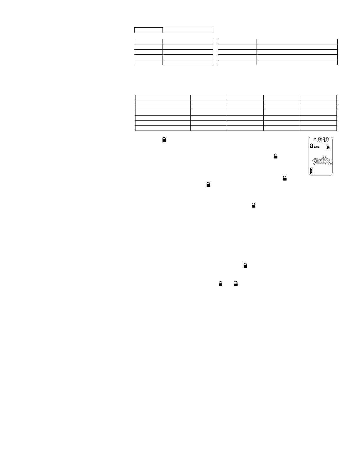
B. THE REMORE LCD ICONS WITH FUNCTION:
C. PROGRAMMING OF THE LCD REMOTE TRANSCEIVER:
Transceiver Button Description Operation
(1 second)
(3 seconds)
Armed Mode
Your motorcycle is in the armed
mode
Remote Transmission
You are transmitting the signal to
control unit
Trigger on the Tilt Switch
(Zone 2) optional
Trigger on the Shock Sensor
(Zone 4)
Trigger on the Ignition Switch
(Zone 5).
Reminder when time is up for
parking
Remote Control vibrates when the
system is triggered
Someone is paging you in front of
your motorcycle
LCD screen lamp turns on for
5 seconds.
Timer Programming Mode. Press and hold the button for
Disarm
The system is Disarmed.
In – Range Indicator
Your are within the remote controls
range.
Trigger on the Close Loop
(Zone 3).
Activate on the Warn away Trigger
You have set morning call alarm
Save the battery power
Disable the transmission function
temporarily
You have to replace the battery of
remote control.
Press and hold the button for
1 second, 1 melody sound will
confirm entry.
3 seconds, 2-melody sounds will
confirm entry.
MA-200 OP REV.A 8

Oct/23/2006
-
-
-
(
)
(Bi)
5. Button Lock:
e transmission function of the remote control
activate
icon will displayed on the LCD screen to show
6. Vibration / Melody Mode:
beep sound
(5 seconds)
- (2-second)
(2-second)
- F (2-second)
- (2-second)
1. Screen Lamp ON: Press and hold the button for one second, with one melody sound and the LCD
screen lamp will turn on for 5 seconds.
2. Power Save Mode For Remote Transceiver: While in the power save mode, the LCD
remote transceiver uses no current to save the battery power.
Entry: Press & hold the button for 5 seconds, with one melody sound and
icon on the LCD screen to indicate entry the “power save mode”.
Exit: Press any button of the LCD remote transmitter to exit the “Power Save Mode”.
3. Clear the Flashing Icons and Melody Sound: Pressing the button 3 times within 3 seconds will
clear the flashing icons and melody sound on the LCD screen transceiver
4. Stop The Trigger Melody Sound: While the alarm is triggered the LCD screen will alert the user through
a melody sound and flashing trigger icons. Pressing any button on the LCD remote transmitter will stop the
melody sound only.
This is useful if you want to disable th
temporarily to prevent any inadvertent pressing of buttons by others. Press the
button first, within 3 seconds press and hold the ( ) button for 2 seconds to
or cancel the button lock function, the
the LCD remote transmitter is on “Button Lock”.
Power Save Mode Press and hold the button for
Clear the Flash Icon and Melody
Sound on the LCD Screen Transmitter
Button Lock ( ) enable / disable
Melody / Vibration
Program Count Down Timer ( )
(10-Minute / 20M / 30 M /1Hour /1.5H /
2.0H)
Enable / Disable Bi Sound
Pressing Button
Mode
5 seconds, 1 melody sound to
confirm entry.
Press the
within 5 seconds
Press the
seconds press and hold button
for 2 seconds.
Press the
seconds press and hold button
for 2 seconds.
Press the
seconds press and hold F button
for 2 seconds.
Press the
While
seconds press and hold
button for 2 seconds.
button first within 3
button first within 3
button first within 3
button first within 3
button 3 times
This mode is useful when you are in a noisy place and it is difficult to hear the
from the remote control. The unit will vibrate if your security system is triggered.
Press the button first, within 3 seconds press and hold the ( ) button
for 2 seconds to select the mode of vibration or melody, the icon will displayed
on the LCD screen to show the LCD remote transceiver is on vibration mode.
7. Enable / Disable Bi Sound While Pressing Button:
The unit has a short “bi” sound while pressing the buttons of the LCD screen transceiver.
If you want mute the “bi” sound while buttons are depressed. Press the button first, within 3 seconds
press and hold the (Bi) button for 2 seconds to disable the “bi” sound.
8. Low Battery Indication:
When the power of the battery weakens, it has two short “bi” sound and the unit will flash icon while
pressing the button of the LCD screen transceiver.
9. Set Up Fixed Count Down Timer:
1. Press the button first, within 3 seconds press and hold the F ( ) button for 2 seconds, the
LCD screen will shows icon and timer (ie. 0:10) ,
2. Press the F ( ) button again showing next order time on the screen ( ie.0:20), press them again
MA-200 OP REV.A 9

Oct/23/2006
10
Timer Setting
–
–
button once.
Alert Alarm Time Setting
–
–
Count Down Timer Setting
–
–
(ie.0:30)…..and so on.
3. Leave the buttons starting count down then icon flashes
Note: 1.The count down period is fixed as 10 minutes, 20 minutes, 30 minutes, 1 hour, 1.5 hours and 2
hours maximum.
2.When the count down timer is showing 0:00 the timer has elapsed.
3. Press button for real time indication when the timer is counting down.
10. Out Of Range Indication:
The system will automatically check the range every 30 minutes when armed.
1. If the user is within the range, the icon will display on the LCD screen.
2. If the user is out of range, it has five short “bi” sounds and the icon will disappear on the LCD
screen.
Note: Programming “Out Of Range Indication” will decrease the life expectancy of battery.
D. TIMER SETTING:
Transceiver Button Description Press Transceiver Button
1 Press & Hold the
button for 3 seconds
Press the button once Time setting (Minute)
2 Press the
Press the button once Alert Alarm Time Setting (Minute)
Press the button once Alert Alarm Setting ON / OFF
3 Press the button once
Press the button once Count down Timer Setting (Minute)
Press the button once Count down Timer Setting ON / OFF
EXIT: Press and hold the button for 2 seconds or leave it for 10seconds, the system will exit the
programming mode.
1. Timer Setting: Example to AM10:30
1. Press & hold the button for 3 seconds, with two-melody sound the “Hours” digit will flash for
adjusting.
2. Press the or F button to decrease or increase the “Hour” digit until AM10:xx
3. Press the button once again then the “Minute” digit flashes for adjusting.
4..Press the or F button to decrease or increase the “Minutes” digit until AM 10:30
5. Press the button for 2 seconds with one-melody sound will confirm exit of the timer program mode.
2. Alert Alarm Timer Setting: Example to PM 6:30
1. Press & hold the button for 3 seconds, two-melody sound and the “Hours” digit will flash for
adjusting.
2. Press the button twice, the LCD screen will shows icon and “Hours” digit will flash for
adjusting.
3. Press the or F button to decrease or increase the “Hour” digit until PM 6:xx
4. Press the button once again then the “Minutes” digit flashes for adjusting.
5. Press the or F button to decrease or increase the “Minutes” digit until PM 6:30
6. Press the button once again then icon flashes for alert alarm “ON / OFF” setting
7. Press the F button to start the “Alert Alarm Timer”, and the “ON” icon will show on the LCD screen.
Press the button to stop the “Alert Alarm Timer”, and the “OFF” icon will show on the LCD screen.
8. Press button for 2 seconds with one-melody sound to confirm exit the timer program mode.
3. Count Down Timer Setting: Example Set count down timer at 2:30
1. Press & hold the button for 3 seconds, with two-melody sound the “Hours” digit will flash for
adjusting.
2. Press the button 5 times, the LCD screen will shows icon and “Hours” digit is flashing for
adjusting.
*Flash digit for adjusting
*Flash digit for adjusting
*Flash digit for adjusting
*Flash digit for adjusting
*Flash digit for adjusting
(Max.19 hours 59 minutes)
*Flash digit for adjusting
(Hour)
(Hour)
(Hour)
for
and F for +
for
and F for +
for
and F for +
for
and F for +
for
OFF and F for ON
for
and F for +
for
and F for +
for
OFF and F for ON
MA-200 OP REV.A

Oct/23/2006
11
3. Press the or F button to decrease or increase the “Hour” digit until 2:xx
4. Press the button once again then the “Minutes” digit flashes for adjusting.
5. Press the or F button to decrease or increase the “Minute” digit until 2:30
6. Press the button once again then the icon will flash for alert alarm “ON / OFF” setting.
7. Press the F button to start the count down timer, and the “ON” icon will show on the LCD screen.
Press the button to stop the count down timer, and the “OFF” icon will show on the LCD screen.
8. Press the button for 2 seconds and one-melody sound will confirm exit of the timer program mode.
Note: Maximum timer mode is 19 hours.
This device complies with part 15 of the FCC rules. Operation is subject to the following two conditions.
(1) This device may not cause harmful interference, and
(2) This device must accept any interference received, including interference that may cause undesired
operation.
LIMITED LIFETIME WARRANTY PROVISIONS
( U.S. ,Continental U.S. and Canada Only)
1. Auto Page, Inc. WARRANTS that this new unit has been thoroughly inspected and tested at the factory prior to delivery. Your
Auto Page equipment is guaranteed for “life” to the original purchaser/user of the equipment and the original vehicle in which it was
installed by an authorized installer under the following conditions: If the product proves defective (according to Auto Page's testing)
within the first year, the defective unit may be exchanged or repaired free of charge. “Proof of Purchase” (dated sales receipt)
must accompany all warranty returns; otherwise, your return will be rejected and sent back. After one (1) year, the purchaser
should ship the unit prepaid to Auto Page with a money order in the amount of $30.00 to cover shipping and handling charges.
Note: The product needs to be registered online at time of installation. www.autopageusa.com
2. This WARRANTY will be considered void if the equipment has been misused, neglected, improperly serviced or installed, altered,
dropped or damaged by water, contrary to the Auto Page OPERATIONS MANUAL. Or, if used with accessories not approved by
Auto Page, which may have contributed to the defect. See note below regarding product installation**.
3. The purchaser’s remedies under this WARRANTY shall be limited to the repair or replacement of electronic components only.
THE FOLLOWING IS NOT COVERED: Damages or deterioration to cases, batteries, covers and cabinets; the cost of repairs,
replacement and labor of which shall be borne by the purchaser even if occurring during the WARRANTY period.
4. Any equipment or parts which are claimed to be defective under this WARRANTY must be sent to the Auto Page Service center
with “proof of purchase” at the purchaser’s expense prior to such return, a Return Authorization Number should be obtained. Auto
Page will return the equipment, charges prepaid. Warranty Service can be provided through the dealer where the equipment is
originally purchased.
5. Any unexpired WARRANTY shall be applicable to equipment and parts in the possession of the original purchaser only.
6. THIS WARRANTY IS IN LIEU OF ANY AND ALL OTHER WARRANTIES, EXPRESSED OR IMPLIED, INCLUDING BUT NOT
LIMITED TO ANY WARRANTY OF MERCHANTABILITY OR FITNESS FOR A PARTICULAR PURPOSE.
7. Auto Page shall not be liable, under the foregoing WARRANTIES or otherwise, for: Any personal injury of any kind to the purchaser,
its employees or agents or anyone else whomsoever resulting directly or indirectly from the use or presence of the equipment or
parts; Consequential damages of any kind; any inability of the purchaser to use the equipment.
**IMPORTANT NOTE: Any damages to the alarm system resulting from an installation performed by anyone other than a
professional installation technician authorized by a dealer of Auto Page will void the product’s limited lifetime warranty.
Auto Page Warranty:
You must register your product online at http://www.autopageusa.com to receive any warranty
service.
Please go to the customer service tab and select product registration.
It is the purchaser’s responsibility to register this product for any future warranty
service.
MA-200 OP REV.A

Oct/23/2006
12
Warning: Some batteries may contain Perchlorate
What is Perchlorate? Perchlorate is both a naturally occurring and manmade contaminant increasingly found in
groundwater, surface water and soil. Most perchlorate manufactured in the U.S. is used as an ingredient in solid fuel for rockets
and missiles. In addition, perchlorate-based chemicals are also used in the construction of highway safety flares, fireworks,
pyrotechnics, explosives, common batteries, and automobile restraint systems. Perchlorate contamination has been
reported in at least 20 states. Perchlorate greatly impacts human health by interfering with iodide uptake into the thyroid gland.
In adults, the thyroid gland helps regulate the metabolism by releasing hormones, while in children; the thyroid helps in proper
development. Perchlorate is becoming a serious threat to human health and water resources.
“Perchlorate Material – Special handling may apply.”
For more information, go to http://www.dtsc.ca.gov/hazardouswaste/perchlorate/
MA-200 OP REV.A
960 Knox Street Unit B, Torrance, CA 90502
Tel: (310) 323-1800 or (800) 262-2527 www.autopageusa.com
 Loading...