

DRW160444AD
Autonics
Refrigeration Temperature Controller
TF3 SERIES
I N S T R U C T I O N M A U A L
Please read the following safety considerations before use.
Safety Considerations
Please observe all safety considerations for safe and proper product operation to avoid hazards.
※
symbol represents caution due to special circumstances in which hazards may occur.
※
Warning
Caution
Warning
1. Fail-safe device must be installed when using the unit with machinery that may cause serious injury
or substantial economic loss. (e.g. nuclear power control, medical equipment, ships, vehicles,
railways, aircraft, combustion apparatus, safety equipment, crime/disaster prevention devices, etc.)
Failure to follow this instruction may result in re, personal injury, or economic loss.
2. Install on a device panel to use.
Failure to follow this instruction may result in electric shock or re.
3. Do not connect, repair, or inspect the unit while connected to a power source.
Failure to follow this instruction may result in electric shock or re.
4. Check 'Connections' before wiring.
Failure to follow this instruction may result in re.
5. Do not disassemble or modify the unit.
Failure to follow this instruction may result in electric shock or re.
Caution
1. When connecting the power, communucation input and relay output, use AWG 28~12 cable and
tighten the terminal screw with a tightening torque of 0.4N.m for the power, communucation input
teminal, and use AWG 28~12 cable and tighten the terminal screw with a tightening torque of 0.5N.m
for the relay outputl.
When connecting the sensor input cable without dedicated cable, use AWG 30~14 cable and tighten
the terminal screw with a tightening torque of 0.2N.m.
Failure to follow this instruction may result in re or malfunction due to contact failure.
2. Use the unit within the rated specications.
Failure to follow this instruction may result in re or product damage.
3. Use dry cloth to clean the unit, and do not use water or organic solvent.
Failure to follow this instruction may result in electric shock or re.
4. Do not use the unit in the place where ammable/explosive/corrosive gas, humidity, direct sunlight,
radiant heat, vibration, impact, or salinity may be present.
Failure to follow this instruction may result in re or explosion.
5. Keep metal chip, dust, and wire residue from owing into the unit.
Failure to follow this instruction may result in re or product damage.
Ordering Information
00
TF
3 3 3 4 H T
Digits
Item
※
1: Only for 1CH input, compressor output model (TF31-1
※
2:
Only for 3CH input model (TF33- - . Option function is varied by compressor load capacity and contact.
Option function
Compressor
load capacity & contact
Compressor 5A 1a
contact
Compressor 16A 1c
1s:1.
contact
※
3: Except compressor+defrost or auxiliary (alarm/evaporator-fan) output model (TF33-2-
※
Only for 3CH input, compressor+defrost+auxiliary (alarm/evaporator-fan) output model (TF33-3)
supports buzzer.
※
The above specications are subject to change and some models may be discontinued without notice.
Be sure to follow cautions written in the instruction manual, user manual and the technical
※
descriptions (catalog, homepage).
Thank you for choosing our Autonics product.
Failure to follow these instructions may result in serious injury or death.
Failure to follow these instructions may result in personal injury or product damage.
Option
function
-9.______________f---------+-1-----------,
Compressor
load capacity
Power supply
Output
Number of input channels
Synchronize
defrost function
(TF33- A-S) (TF33- A-T)
DD
- -
No-mark No option
S Synchronize defrost
※
2
T RS48 5 communication
※
3
R
RTC (real time clock)
※
3
A
RS485 communication+RTC (real time clock)
※
1
G
Compressor 20A 1a contact
A
Compressor 5A 1a contact
H
Compressor 16A 1c contact
1 24VAC 50/60Hz, 12-24VDC
4 100-240VAC 50/60Hz
1CH 1 Compressor output
Compressor+Defrost or Auxiliary
2
(alarm/evaporator-fan) output
1CH,
3CH
Compressor+Defrost+Auxiliary
3
(alarm/evaporator-fan) output
1
1CH input (NTC or RTD) [temperature+digital input (DI)]
3CH input (NTC)
3
[inlet temperature+defrost temperature+
outlet temperature or digital input (DI)]
3 999 (3 digit)
TF Refrigeration Temperature Controller
G).
DD
□
RTC function
-
I.
(TF33-3 H-R)
□□□□
RS485
communication
I·
RS485
communication+RTC
function
(TF33-3A-A)
□
I·
□
-
□□□
No option
-
I.
(TF33- H)
□□□
Specications
00
g
TF3 Series
Model TF31- TF33- Number of channels 1CH 3CH
AC power 100-240VAC
Power
I
supply
AC/DC power 24VAC 50/60Hz, 12-24VDC
I
Allowable voltage range 90 to 110% of rated voltage
AC power Max. 8VA (100-240VAC 50/60Hz)
Power
I
consumption
AC/DC power Max. 5VA (24VAC 50/60Hz), Max. 3W (12-24VDC )
I
Display method 7 Segment LED method (red)
Character size (W×H) 9.4×19.3mm
NTC 5kΩ/10kΩ
I
Input type
RTD DPt100Ω
I
Sampling period 500ms
Display accuracy
Compressor (COMP)
Control
Defrost (DEF) 250VAC 10A, 24VDC 10A, 1a
output
Auxiliary (AUX) 250VAC
Communication output
Digital input
Control method ON/OFF control
Hysteresis 0.5 to 5 0℃, 2 to 10℉ variable
Relay
life
cycle
Memory retention Approx. 10 years (non-volatile memory method)
Insulation resistance Min. 100MΩ (at 500VDC megger)
Dielectric
strength
Noise resistance
Vibration
Environment
Accessories Bracket: 2, NTC sensor (5kΩ): 1
Protection structure IP65 (front case)
Approval
Weight
g
Remote display unit [TFD, sold separately]
Model TFD-3 TFD-5
Power supply 3.3VDC
Power consumption
Display method 7 Segment LED method (red)
Comm. method Serial (TTL Level), Half duplex Protection structure P67
Comm. cycle 100ms Approval
Cable Ø2.5mm, 3m Ø2.5mm, 5m Weight
I I : I
※
The weight includes packaging. The weight in parentheses is for unit only. The weight is varied by model option.
1.
※
Environment resistance is rated at no freezing or condensation.
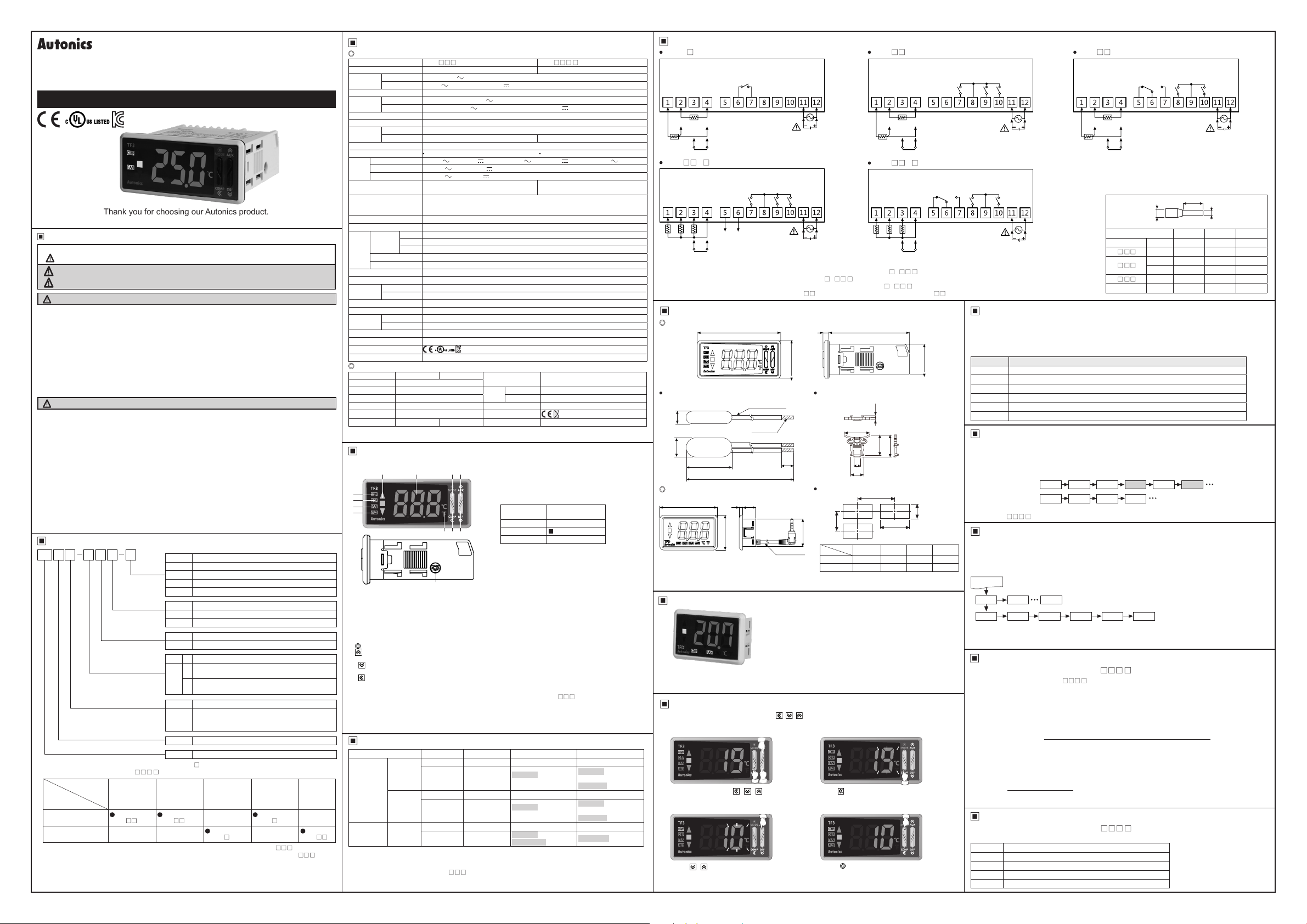
Part Description
00
3
4
5
6
~
4. Defrost (DEF) output indicator (green)
Turns ON for defrost output. Flashes for defrost delay operation.
T
urns ON for 2 sec and OFF for 1 sec for manual defrost or Power ON defrost.
5. Evaporator-fan (FAN) output indicator (green)
Turns ON for evaporator-fan output. Flashes for delay operation of evaporator-fan output.
Auxiliary (AUX) output indicator (green)
6.
Turns ON for alarm output. Flashes for delay operation of alarm output.
7. Unit indicator (red) Displays temperature unit set at temperature unit [
8.
(MODE) key
9. (AUX) key
Hold the key over 3 sec to select active/inactive auxiliary output in RUN mode.
(DEF) key
10.
Hold the key over 3 sec to execute/stop manual defrost in RUN mode.
(COMP) key
11.
Hold the key over 3 sec to active/inactive compressor output in RUN mode.
When buzzer alarm occurs, press the key once to stop the sound. (Only for 3CH input,
compressor+defrost+auxiliary (alarm/evaporator-fan) output model (TF33-3
Buzzer [BU] of parameter 1 group is set as [ON])
12. Data loader port
It is for displaying
connecting Autonics SCM-US (USB/Serial converter, sold separately), it is a PC loader port of serial
communication for parameter setting by PC.
Input Type and Temperature Range
00
Input type Decimal point Display method Temperature range (℃) Temperature range (℉)
Thermistor
(NTC)
※
DD
1
RTD
※
TF3 Series displays only 3 digits. If PV decimal number of shaded temperature range is out of 3 digit,
TF3 does not display the numbers below decimal point. You can check it at the comprehensive device
management program (DAQMaster) by communicating via PC.
※
1: Only for 1CH input model (TF31- ).
※
2: If PV with "-" sign is over 3 digits (e g.: -99 9), the numbers below decimal point does not display. You can
check it at the comprehensive device management program (DAQMaster) by communicating via PC.
5A 1a Mechanical: 5,000,000 operations, Electrical: 50,000 operations (250VAC 5A)
I
Compressor
16A 1c Mechanical: 20,000,000 operations, Electrical: 30,000 operations (250VAC 16A)
I
(COMP)
20A 1a Mechanical: 10,000,000 operations, Electrical: 100,000 operations (250VAC 20A)
I
Defrost (DEF) Mechanical: 20,000,000 operations, Electrical: 100,000 operations (250VAC 10A)
Auxiliary (AUX) Mechanical: 5,000,000 operations, Electrical: 50,000 operations (250VAC 5A)
AC power 3000VAC 50/60Hz for 1 min (between all terminals and case, power and input circuit)
I
AC/DC power 1000VAC 50/60Hz for 1 min (between all terminals and case power and input circuit)
I
Ambient temp.
I
Ambient humi.
I
※
1
Max. 1W
m:1
Used for entering parameter setting group, returning RUN mode, moving parameter or saving SV.
Used for entering SV setting group or changing setting value.
Used for entering SV setting group or changing setting value.
Used for entering SV setting group, changing setting value, moving digits.
TF3 data at remote display unit (TFD) by connecting phone-jack. In other case, for
NTC 5kΩ
NTC 10kΩ
DPt 100Ω
□□□
'v
50/60Hz
'v
'v
At room temp. (23
250 VAC 5A, 30V DC 5A, 1a / 250VAC 16A, 2 4VDC 16A, 1c / 250VAC 20 A 1a
-
Contact input: ON Max. 1㏀ , OFF Min. 100
No contact
Square-wave noise by the noise simulator (pulse width: 1㎲) ±2kV R-phase and S-phase
1.5mm amplitude at frequency of 10 to 55Hz (for 1 min) in each X, Y, Z direction for 2 hours
-10 to 50℃, storage: -20 to 60
35 to 85%RH, storage: 35 to 85%RH
CE
,@--,
Approx. 207g (approx. 105g)
1 8 92
℃±5℃
'v
'v
'v
5A, 30VDC 5A, 1a
input: ON residual voltage: Max. 1V, OFF leakage current: Max. 1mA,
outow current: 4
[:{\
7 11 10
! 9
12
1
0.1
1
0.1
1
0.1
N%H
N%L
N!H
N!L
DpH
DpL
□□□
I
□□□□
I
---
'v
): ±1℃±1 digit
---
-
Vibration
Enviornment
-
'v
㎂
℃
Ambient temp.
Ambient humi.
※
1
1. Present value (PV) display component (red)
RUN mode: Displays present value (PV).
Setting mode: Displays parameter and setting value.
2. Deviation indicator (■ green, ▼/▲ red)
Displays deviation of present value (PV) based on
setting value (SV).
PV deviation
temperature
More than 1.8℃ ▲ indicator turns ON
Within ±1 8
Less than -1 8
3. Compressor (COMP) output indicator (green)
Turns ON for compressor output. In case of
compressor protection operation and output does not
turn ON, it ashes.
When operating compressor continuously, it turns ON
for 2 sec, and turns OFF for 1 sec.
-40 to 99 -40 to 212
-40 to -20
-19.9 to 99 9
-40 to 99 -40 to 212
-40 to -20
-19.9 to 99 9
-99 to 99 -148 to 212
-99 to -20
-19.9 to 99 9
---
-
I
Out of room temp. range: ±2
---
RS485 communication output
(Modbus RTU)
I
㏀
1.5mm ampl tude at frequency of 10 to 55Hz
(for 1 min) in each X, Y, Z direction for 2 hours
-10 to 50℃, storage: -20 to 60
35 to 85%RH, storage: 35 to 85%RH
Approx. 77g (approx. 48g)
Deviation display
indicator turns ON
℃
▼ indicator turns ON
℃
I-
] of parameter 1 group.
UNT
-
supports buzzer.
□□□
-40 to -20
-19.9 to 99.9
100 to 212
-40 to -20
-19.9 to 99.9
100 to 212
-148 to 212
※
2
~
_J
7
_J
7
Connections
TF31-1 G
COMP OUT
250VAC 20A
RESISTIVE LOAD
NTC 5K/10K
±1 digit
℃
'v
℃
DPt100
SENSOR
DIGITAL INPUT
TF33- A-
•
□□
□
COMP OUT
250VAC 5A
30VDC 5A
RESISTIVE
LOAD
S1 S2 S3 COM
A+ B-
NTC 5K/10K
SENSOR
DIGITAL INPUT
※
1: Only for compressor+defrost or auxiliary (alarm/evaporator-fan) output model (TF3 -2 - ), compressor+
defrost+auxiliary (alarm/evaporator-fan) output model(TF3 -3 - ).
※
2: Only for compressor+defrost+auxiliary (alarm/evaporator-fan) output model (TF3 -3 - ).
※
3: Only for synchronize defrost function model (TF33- A-S), or RS485 communication model (TF33- A-T/A).
Dimensions
00
g
TF3 Series
NTC sensor (5kΩ)
•
! (
Max. 5
I
6±0 2
t<-------------r-
q
g
TFD (sold separately)
52
SYNCHRONIZE
/RS485
i~
~~~~
:1
~)=S=-:7,
Max. 15
※
3
77
o o 'li'TIJ
AWG22
TPE lead wire
Soldering
2000±50
3
12
31.5
DEF OUT
250VAC 10A
24VDC 10A
RESISTIVE
※
LOAD
~~
AUX OUT
250VAC 5A
30VDC 5A
RESISTIVE
1
LOAD
35
5±1
g
Ø2 5
3m or 5m
SOURCE
100-240VAC 50/60Hz,
24VAC 50/60Hz,
12-24VDC
2
※
SOURCE
100-240VAC 50/60Hz,
24VAC 50/60Hz,
12-24VDC
□
□□□
□□
5 5
-~·t
Bracket
•
Panel cut-out
B
25
Series
TF3
TFD Min. 65 Min. 40 45.7
※
1. When connecting remote display unit (TFD),
or SCM-US, Min. 120
Remote Display Unit (TFD) [sold separately]
Remote display unit (TFD) displays current temperature or output status
of TF3 at remote place. TFD cable is TFD-3: 3m, TFD-5: 5m.
Connect the phone-jack of remote display unit (TFD) to the data loader
port of TF3. This unit is dedicated for TF3 Series and it does not directly
communicate with upper devices (PC, PLC, etc.)
If TFD communication with TF3 error occurs, TFD ashes display
component for 1 sec. Check the connection with TF3.
※
When connecting TFD to the data loader port of TF3, you cannot connect Autonics SCM-US (USB to Serial
converter, sold separately) for communication. Use SCM-US48 (USB to RS485 converter, sold separately),
SCM-38 (RS232C to RS485 converter, sold separately).
SV Settings
00
You can set the temperature to control with keys.
Set range is within SV low-limit value [
E g.) In case of changing SV from 19℃ to 10
① ②
Press any key among
mode to enter into SV setting mode.
Last digit (10
③ ④
,
Press
Iii
or lower the set value. (9 → 0)
, ,
0
digit) on SV display part
key to raise
~
] to SV high-limit value [
LSV
℃
in RUN
ashes.
HSV
Press
(100→ 10¹→ 10²→10³→ 100)
Press
If there is no additional key operations in 3 sec,
the changed SV is automatically saved.
TF31- A
•
□□
NTC 5K/10K
DPt100
SENSOR
DIGITAL INPUT
TF33- H-
•
□□
□
COMP OUT
250VAC 16A
24VDC 16A
RESISTIVE
LOAD
S1 S2 S3 COM
NTC 5K/10K
!_!
SENSOR
DIGITAL INPUT
□
□□□
□
□□□
74.3
G@
G
!
3.3
i
ocl!=!=~
4
46
_________.,
37.5
pi
12
23 9
Size
A B C D
Min. 100
].
key to move digit.
(MODE) key to save the set value.
40.5
A
C
※
1
Min. 55 70 3
D
0.7
0
0.6
0
TF31- H
COMP OUT
250VAC 5A
30VDC 5A
RESISTIVE
LOAD
@~~~~11
(unit: mm)
28
(unit: mm)
□□
28.2
25.4
DEF OUT
250VAC 10A
24VDC 10A
RESISTIVE
LOAD
DEF OUT
250VAC 10A
24VDC 10A
RESISTIVE
LOAD
AUX OUT
250VAC 5A
30VDC 5A
RESISTIVE
1
※
1
※
2
※
LOAD
SOURCE
100-240VAC 50/60Hz,
24VAC 50/60Hz,
12-24VDC
AUX OUT
250VAC 5A
30VDC 5A
RESISTIVE
2
※
LOAD
12
SOURCE
100-240VAC 50/60Hz,
24VAC 50/60Hz,
12-24VDC
Comprehensive Device Management Program
00
[DAQMaster]
DAQMaster is comprehensive device management program. t is available for parameter setting, monitoring ,
and user parameter group setting, parameter mask setting for only TF3 Series.
Item Minimum specications
System IBM PC compatible computer with Pentium Ⅲ or above
Operations Windows 98/NT/XP/Vista/7/8/10
Memory 256MB+
Hard disk 1GB+ of available hard disk space
VGA Resolution: 1024×768 or higher
Others RS232C serial port (9-pin), USB port
Parameter Mask
00
This function is able to hide unnecessary parameters to user environment or less frequently used parameters in
parameter group. You can set this in the comprehensive device management program (DAQmaster).
Masked parameters are only not displayed. The setting value of masked parameters are applied.
For more information, refer to DAQMaster user manual.
Visit our web site to download DAQmaster program and the user manual.
Before applying mask
After applying mask
The above is masking input sensor 3 selection [S3], temperature unit [
model (TF33-
Parameter User Group [
This function is able to set the frequently used parameters to the user parameter group. You can quickly and
easily set parameter settings. User parameter group can have up to 30 parameters in the comprehensive device
0 5
management program (DAQMaster).
0
For more information, refer to the DAQMaster user manual.
0 3
0
RUN mode
PAU PA1 PA5
DsT HYS nHY DEF DET aHY
The above is setting user parameter group in the DAQMaster with delay display period [
group, hysteresis [
[
] of parameter 3 group, alarm output hysteresis [
DET
Virtual Temperature Rate [
00
~--·
- ).
□□□□
], night mode hysteresis [
HYS
•
NTC 5K/10K
DPt100
SENSOR
PA1 INT S2 S3 VtR UNT
PA1 INT S2 VtR
(only for 3CH input model: TF33- - )
In case of 3CH input model (TF33temperature [TS]. You can set virtual temperature rate.
If the temperature of inlet and outlet is signicantly dierent at freezer, virtual temperature helps to control
temperature eciently.
Virtual temperature is designated by the rate of input sensor 1 (inlet temperature) and input sensor 3 (outlet
temperature). There is virtual temperature calculation formula.
Virtual temperature (PV)=
If virtual temperature rate [
If virtual temperature rate [
E g.) If inlet temperature of input sensor 1 is 0
set virtual temperature rate [
[{100-50}×0]+ [50×10]
5=
Setting range of virtual temperature rate: 0 to 100 (%)
Display Selection [
00
(only for 3CH input model: TF33- - )
You can select input sensor to display at present value (PV) display component in RUN mode.
Parameter Description
Displays PV of input sensor 1 (inlet temperature).
S1
Displays PV of input sensor 2 (defrost temperature).
S2
Displays PV of input sensor 3 (outlet temperature).
S3
Displays virtual temperature.
VS
[{100-virtual temperature rate} × input sensor 1 temperature]
VtR
VtR
100
- ), input sensor 3 selection [S3] of parameter 1 group is set as outlet
□□□□
+ [virtual temperature rate × input sensor 2 temperature]
] is set as [0], virtual temperature (PV)= input sensor 1.
] is set as [
VtR
], virtual temperature (PV)= input sensor 3
100
℃
] as [50] and virtual temperature is 5℃ to control temperature.
DpT
□□
COMP OUT
250VAC 16A
24VDC 16A
RESISTIVE
LOAD
DIGITAL INPUT
※
Use crimp terminals of size specied below.
Terminal number a b c
General 1 to 4 4 to 6 Max. 1.7 Max. 3.7
TF3
H 5 to 10 6 to 8 Max. 2 3 Max. 4 5
□□□
TF3
A
□□□
TF3
G 6 to 7 6 to 8 Max. 2 3 Max. 4 5
□□□
General 11 to 12 6 Max. 1 9 Max. 4 0
PAU
]
] of parameter 2 group, defrost method [
nHY
] of parameter 4 group.
aHY
VtR
DEF OUT
250VAC 10A
24VDC 10A
RESISTIVE
LOAD
c
t=of
<Crimp terminal>
5 to 6 6 Max. 1 9 Max. 4 0
7 to 10 6 to 8 Max. 2 3 Max. 4 5
] of parameter 1 group for 3CH input
UNT
AUX OUT
250VAC 5A
30VDC 5A
RESISTIVE
1
※
LOAD
a
l=t
DsT
2
※
SOURCE
100-240VAC 50/60Hz,
24VAC 50/60Hz,
12-24VDC
b
] of parameter 1
], defrost time
DEF
]
□□□□
100
, and outlet temperature of input sensor 3 is 10℃,
]
□□□□
(unit: mm)
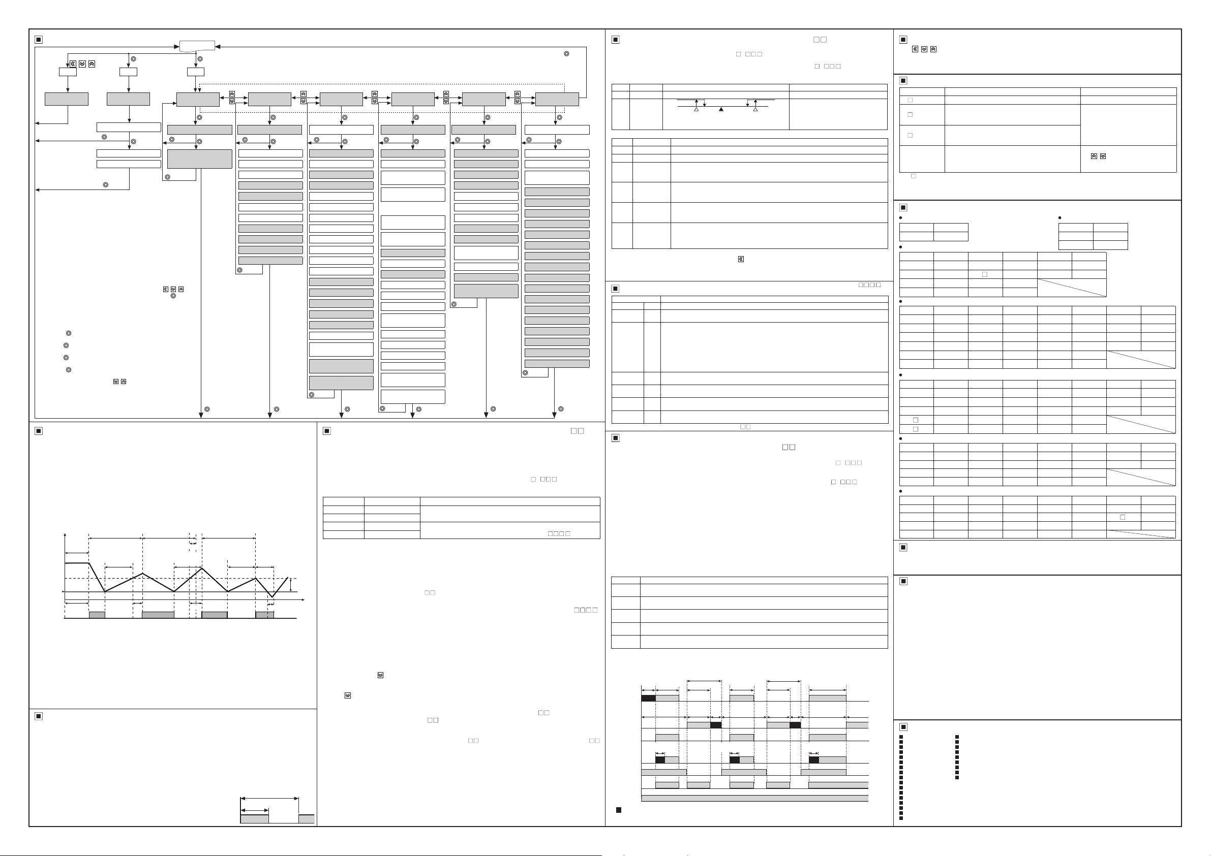
Parameter Group
00
Press any key among
, once
※
1
PS PSPS
~
~~
SV setting
[S]
I
※
1. [
] parameter appears only when password is set.
PS
The default password is [
password code appears. Press any key among the
keys to return to password entering window. Press the
(MODE)
If you forget password, contact Autonics after checking
password code.
※
2. It appears when setting user parameter group in the
comprehensive device management program (DAQMaster).
※Pressthe
SV.
※
Hold the
move to the parameter group.
※
Hold the
RUN mode.
※
Press the
parameter group, it moves to that parameter group name. You
can move to other groups with keys.
※
If there is no additional key operation within 30 sec after entering
into setting mode, it will be automatically returned to RUN mode
and previous setting value will be remained.
※
The shaded parameters are displayed when user level [US] of
parameter 5 group is set as standard level [ST].
Compressor Protection
00
This function is for preventing compressor from life cycle shortening or malfunction by overload and frequent
ON/OFF of compressor. As compressor protection settings, when compressor output does not ON, the front
compressor (COMP) output indicator (green) is ashing.
● Compressor start-up delay time [
If power turns ON instantly from break-down or power OFF, it delays start-up during the set time of compressor.
Setting range: 0 to 60 (min)
● Compressor restart delay time [
To prevent frequent compressor ON/OFF, set compressor ON time after compressor turns OFF.
Setting range: 0 to 60 (min)
● Compressor min. operation time [
To prevent frequent compressor ON/OFF, set min. operation time and min. operation cycle.
Setting range of compressor min. operation time: 0 to 60 (min),
Setting range of compressor min. operation cycle: 0 to 60 (min)
Temp.
SV
ON
Comp.
OFF
output
※
1. When starting compressor, if present value (PV) is out of hysteresis range, compressor output does
not turn ON and the compressor (COMP) output indicator is ashing during compressor start-up delay time.
※
2. When compressor delay is completed and it is within compressor min. operation cycle, compressor output
does not turn ON and the compressor (COMP) output indicator is ashing. (The latest one has priority
between compressor restart delay time and compressor min. operation cycle.)
※
3. When present value (PV) is out of hysteresis, compressor output does not turn ON and the
compressor (COMP) output indicator is ashing during compressor restart delay time.
※
4. If present value (PV) is below the SV, compressor output maintains ON status during compressor
min. operation time. After compressor min. operation time, it turns OFF.
※
If compressor output does not turn ON due to compressor output condition or parameter settings for
compressor protection, the compressor (COMP) output indicator is ashing.
For more information about parameters for compressor prevention, refer to user manual.
★
Compressor Control When Sensor Break
00
If normal temperature control is impossible due to sensor break, it controls compressor output by the set operation
cycle and duty ratio to protect control object. Until error is cleared, operation cycle and duty ratio are applied
repeatedly. When error is cleared, the compressor operates after completing the currently applied operation cycle
and compressor restart delay time.
● Compressor operation cycle when sensor break [
Set compressor operation cycle when sensor break.
Set as [0] and compressor output turns OFF when sensor break.
Setting range: 0 to 100 (min)
● Compressor duty ratio when sensor break [
Set compressor ON duty ratio when sensor break.
Setting range: 0 to 100 (%)
E.g.) When compressor operation cycle when sensor break [
is set as 60 min and compressor duty ratio when sensor break
[
DUT
turns ON for 30 min and turns OFF for 30 min.
I ~ I
Saved automatically
after 3 sec
I
@
@
@
@
Compressor
delay time
n c~----~-)----l--f--/f-
1----~-\t/";
~
I '
Monitoring time [
I
@
Max. value [
I
Min. value [
I
@
000
key to return to RUN mode.
) key after changing the setting to save the
(MODE
) key for 1.5 sec while in setting mode to
(MODE
) key for 3 sec while in setting mode to return
(MODE
key at the last parameter of each
(MODE)
Compressor
min. operation cycle
start-up
※
1
: H
] is set as 50%, compressor output has 60 min cycle and
※
1
?
Display selection
[pT]
I
l
]
MoT
1 5 sec
I
. @
]
hPK
]
lPK
1.5 sec
I
]. If password is not valid, the
]
SDL
]
RDL
], Compressor min. operation cycle [
ONT
min. operation cycle
'
'
restart
'
'
Compressor
delay time
: ~:7~-:--~I/" : "
~
※
2
; I I : :
RUN mode
2 sec
※
1
When PW is validWhen PW is validWhen PW is valid
Parameter user group
※
2
[
]
PAU
User parameter 0
@
1.5 sec
I@
• •
User parameter 1 to 29
I I :
@
[§]
Compressor
,
[§11
§I
@
Compressor
delay time
I
3 sec 3 sec 3 sec 3 sec
@ @
min. operation cycle
,.__
' ' '
※
2
' :
restart
~:
※
3
t=::1
]
CLE
]
DUT
]
CLE
Compressor
Input type [
@
Input sensor 2 ON/OFF [S2]
Input sensor 3 selection [S3]
Virtual temperature rate [t]
I
Temperature unit [
I
Input correction 1 [Ib]
I
Input correction 2 [
I
Input correction 3 [
I
Delay display period [sT]
I
Defrost/auxiliary output [
I
Auxiliary output [
I
Buzzer [
I
~
Compressor
__
Compressor
restart delay
time
ON rate (50%)
ON
output
OFF
Parameter 1 group
[PA]
]
I T
1.5 sec 1 5 sec 1.5 sec 1.5 sec 1.5 sec
@
I
I
I
]
U T
I
I
]
Ib2
I
]
Ib3
I
I
]
s A
I
]
AUX
BUZ
]
I
I
"
]
CYC
____,
Compressor
min. operation
time
Hysteresis
I/
!
I~
※
4
t::::h
Operation cycle (60 min)
Parameter 2 group
[
]
PA2
Comp. output mode [FT]
@
I@
•
Hysteresis [
Oset [FS]
SV high-limit [HS]
SV low-limit [LS]
Night mode [nM]
Night mode SV correction [nS]
Night mode hysteresis [
Night mode oset [
Night mode start hour [
Night mode start min [
Night mode end hour [
Night mode end min [
Temperature monitoring [eM]
Comp. start-up delay time [
Comp. min. operation cycle [
Comp. restart delay time [L]
Comp. min. operation time [T]
Comp. continuous operation [CC]
Alarm delay time after
continuous operation [
Comp. operation cycle when
sensor break [
Comp. duty rate when sensor
break [UT]
HYS
CLE
]
nHY
]
n F
nSH
nSM
nEH
nEM
S L
CYC
AdC
]
l@____J I
+ @
Defrost Control
00
When operating a compressor for a long time, an evaporator and a freezer are freezing and thermal eciency
of compressor is decreased. For increasing thermal eciency, defrost operation helps to remove frost or ice
around of evaporator.
Set defrost cycle, time, and end temperature, etc to operate defrost (heater/hot-gas defrost).
The front defrost (DEF) output indicator (green) turns ON during defrost output and it ashes during defrost
delay operation.
In case of compressor+defrost or auxiliary (alarm/evaporator-fan) output model (TF3
operation is available when defrost/auxiliary output [
●Defrost method and operation [
Parameter Defrost method Defrost operation
hTM
gTM
hTT
gTT
I I
●Defrost cycle [
Set defrost cycle and time to operate defrost at every set cycle and during the set time.
Defrost cycle setting range: 0 to 24 (hour)/0 to 100 (min)
Defrost time setting range: 1 to 100 (min/sec)
※
Compressor operation during defrost is varied by defrost method. In case of heater defrost, compressor
output turns OFF, and in case of hot-gas defrost, compressor output turns ON. Evaporator-fan operation is
varied by evaporator-fan operation mode setting.
※
In case of RTC function model (TF33-3 -R/A), defrost operates at every specic time. Set real-time defrost
Time
rDI
cycle [
] of parameter 3 group as [ON] and 8 real-time defrost times are available to set.
●Defrost end temperature [
Set defrost end temperature and defrost hysteresis from input sensor 2 (defrost temperature). When the
measured temperature of defrost sensor is same as the set defrost end temperature, defrost operation is
stopped. It is available when input sensor 2 ON/OFF [S2] is set as [ON] and defrost method and operation [
hTT
is set as [
Defrost end temperature setting range: -40 to 99 (℃) / -40 to 212 (℉)
Defrost hysteresis setting range: 1 to 5 (1.0 to 5.0) (℃) / 2 to 10 (℉)
●Manual defrost
Execute defrost manually regardless of the set defrost cycle which consists of defrost method and operation
setting. Hold the front
is set as [
The front defrost (DEF) output indicator turns ON for 2 sec and turns OFF for 1 sec during manual defrost. Hold
the front
starts.
Defrost synchronization (only for synchronize defrost function model TF33- A-S,
●
RS485 communication model TF33- A-T/A)
When connecting over 2 units of TF3, defrost and compressor operation is able to synchronize via synchronize
terminal/RS485 communication.
It is available for synchronize defrost function model (TF33- A-S), or RS485 communication model (TF33A-T/A).
[Setting Order]
1. Connect each other synchronize terminals or RS485 communication terminals of the units which are
2. Set defrost cycle [
3. Set defrost group [
4. According to defrost operation of Master, the defrost operation of slave(s) executes. (when changing the
※
※
★
] or [
mDF
] to operate defrost during the set defrost time.
key over 3 sec or turn OFF the digital input during manual defrost, and the set defrost cycle re-
synchronized for defrost.
defrost parameters of master, defrost operations of slave(s) are also changed forcibly as same as the defrost
operation of master via connected terminals. The defrost parameters of slave(s) are not changed.)
Defrost operation by real-time defrost cycle is not able to synchronize.
Defrost operation of master is prior to the compressor operation of slave.
For more information about parameters for defrost operations, refer to user manual.
Parameter 3 group
[
PA3
Defrost method & operation [
@
I@
•
Defrost cycle [I]
I I
Real-time defrost cycle
I I
Real-time defrost cycle 1:
I
I
hour [H]
I
Real-time defrost cycle 1:
min [M]
I
I
I
]
I
I
]
I
]
I I
]
I I
]
I I
I I
]
I I
]
I I
: I
I I
I I
]
I I
I I
l@__J
...
Real-time defrost cycle 8:
I
hour [H8]
Real-time defrost cycle 8:
I
min [M8]
Defrost time [
Pump down delay time [Pd]
Defrost end delay time [rT]
Defrost end temperature [
Defrost hysteresis [
Defrost when power ON [
Defrost delay when power ON/
manual defrost [
Defrost group [dG]
Parameter copy [
Prior defrost selection [dP]
I
Defrost time unit [
Alarm delay after defrost/
door open [Ad]
Temperature display during
defrosting [
t E
I
+ @
]
[
r I
]
ET
E T
dHY
p E
]
d E
]
p C
]
u E
]
Parameter 4 group
Alarm operation mode [AL]
]
DEF
@
Alarm option [
I I
]
Alarm high- imit deviation [
I I
Alarm low-limit deviation [
I I
Alarm hysteresis [
I
Alarm ON delay time [a]
I I
Alarm OFF delay time [
I
External alarm delay time [eA]
I I
Alarm output method
I
Evaporator-fan operation [
I I
Evaporator-fan control
I
I
temperature [fT]
I I
Evaporator-fan hysteresis [
I I
Evaporator-fan mode [FA]
]
Evaporator-fan start-up
delay time [p]
]
: I
I
_@_______j
]
I
I
I
I
I
I
I
[
]
PA4
I@
•
]
AlT
AlH
AlL
]
aHY
a F
[a]
f Y
fHY
@
3 sec 3 sec
1
(except 1CH, compressor output model: TF31-1 )
] of parameter 1 group is set as defrost [
sDA
]
DEF
Heater defrost
Hot-gas defrost
heater defrost
Hot-gas defrost
], Defrost time [
DIN
gTT
].
key over 3 sec or, turn ON the digital input when digital input [
Operates during the set defrost cycle/time
Operates when PV is lower than defrost end temperature during the set
defrost cycle/time (only for 3CH input model (TF33-
]
DET
□□
], Defrost hysteresis [
EDT
] (only for 3CH input model TF33- )
dHY
□□
□□
DIN
] same as among the units. (if error occurs, defrost cycle is the setting of each unit)
dGR
] as 1 master unit [
MAS
] and slave unit(s) (up to 5 units) [
Parameter 5 group
[
PA5
Current hour [
@
•
Current minute [
I I
]
Digital input [I]
I I
]
Loop break alarm
I
I
monitoring time [
I
Comm. address [A]
I I
Comm. speed [
I I
]
Comm. parity bit [
I I
Comm. stop bit [
I I
Comm. response wait time [ ]
I
I
]
Comm. write [
User level [US]
I :
]
SV setting group lock [lS]
I I
Front key lock [
I I
PA 0 group lock [
I I
PA user group lock [
I
PA 1 group lock [lP]
I
PA 2 group lock [
I
PA 3 group lock [
I
PA 4 group lock [
I
PA 5 group lock [
I
Password [PW]
I
~
,
-2 - ) , defrost
□
□□□
□□□□
DI
] of parameter 5 group
□□
SLA
].
@
]
CUH
CUM
LBA
BPS
STP
C W
l K
@
DEF
- ))
3 sec
]
]
]
]
]
P T
]
]
]
]
lP0
lPU
]
lP2
]
lP3
]
lP4
]
lP5
□□
].
□□□□
Alarm
00
Set both alarm operation and alarm option by combining. Alarm function is available for compressor+defrost or
auxiliary (alarm/evaporator-fan) output model (TF3
1 group should be set as auxiliary [
In case of compressor+defrost+auxiliary (alarm/evaporator-fan) output model (TF3
[
] of parameter 1 group should be set as alarm [
AUX
●Alarm operation [AL]
Mode Name Alarm operation Description
OFF
AlD
I I
●Alarm option [
Mode Name Description
AlA
I
AlB
I
AlC
I
I
Al
I
AlE
I
I
I
AlF
I
※
1: To clear alarm, turn OFF the power (also digital input [
]
I
I
I
I
I
I
I
I
I
I
I
DEF
□□
pausing compressor output) or press the front
※
2: Condition of re-applied standby sequence for standby sequence: Power ON, changing temperature,
alarm settings, switching STOP mode to RUN mode (also digital input [DI] is set as RUN/STOP [
input turns OFF from ON for operation mode by releasing pause compressor output)
Digital Input [DI]
Parameter Function
OFF
RUN/STOP
Door switch
Night mode
ON/OFF
External
alarm
Defrost
ON/OFF
Manual
defrost
※
1. Except 1CH, compressor output model (TF31-1
Evaporator-fan Control
00
(except 1CH, compressor output model: TF31-1 )
To improve the eciency of cooling, install and control evaporator-fan at evaporator.
It is available for compressor+defrost or auxiliary (alarm/evaporator-fan) output model (TF3
defrost/auxiliary output [
should be set evaporator-fan [
It is available for compressor+defrost+auxiliary (alarm/evaporator-fan) output model (TF3
auxiliary output [
●Evaporator-fan operation [
Evaporator-fan operates by two control methods; [
defrost sensor or [
●Evaporator-fan control temperature [fT] and hysteresis [
When evaporator-fan operation [
temperature from defrost sensor), and the temperature of defrost sensor is same as evaporator-fan control
temperature [fT], evaporator-fan output turns OFF. Set evaporator-fan control temperature [fT] and evaporatorfan control hysteresis [
Evaporator-fan control temperature setting range: -40 to 99 (℃), -40 to 212 (℉)
Evaporator-fan control hysteresis setting range: 1 to 5 (0 5 to 5 0) (℃), 2 to 10 (℉)
●Evaporator-fan operation mode [
When evaporator-fan operation [
to set [
Parameter Operation method
EF
EF2
EF3
EF4
]
EF5
If evaporator temperature is increased by defrost operation, warm air may ow into cooling system by
evaporator-fan operation. Set evaporator-fan start-up delay time [
increase cooling eciency.
Evaporator-fan start-up delay time setting range: 0 00 to 9.59 (0 min 00 sec to 9 min 59 sec)
Compressor
: Output does not turn ON but the dedicated indicator ashes at the delay period (compressor, defrost,
※
■
For more information about parameters for evaporator-fan control, refer to user manual.
★
(except 1CH, compressor output model: TF31-1 )
-2 ). Also defrost/auxiliary output [
□
], and auxiliary output [
AUX
ㅡ ㅡ
Deviation
high, lowlimit alarm
※
1
※
I
AlT
Standard alarm If it is an alarm condition, alarm output is ON. If it is a clear alarm condition, alarm output is OFF.
※1
Alarm latch
Standby
sequence 1
Alarm latch and
standby
sequence 1
Standby
sequence 2
Alarm latch and
standby
sequence 2
No digital input
FF
Pauses compressor output. All output indicators turn OFF. When digital input is OFF, it controls
STP
normally after compressor restart delay time.
By connecting freezer door switch and digital input contact, it controls compressor/defrost/
evaporator-fan according the door status.
- Digital input ON (door open): Compressor, defrost, evaporator-fan output turns OFF
- Digital input OFF (door close): After 1 min, it returns the previous status of door open.
dSW
Alarm occurs after the time of alarm delay after defrost/door open [Ad] of parameter 3 group.
When operating compressor continuously, compressor start-up time is extended as long as the door
open time.
When digital input turns ON, night mode is active.
nM
When digital input turns ON, alarm output turns ON forcibly. (except alarm is ON) When external
eAL
alarm delay time [eA] of parameter 4 group is set, alarm turns ON after the set time.
When digital input turns ON and it is defrost operation condition, defrost output turns ON.
※
e F
1
Even though it is defrost operation condition, if digital input turns OFF, defrost output turns OFF also.
When digital input turns ON, it executes manual defrost.
m F
1
t j: j: t
I:;
PV -10℃ PV 20℃SV 0℃
High-limit deviation [
Low-limit deviation [
]
If it is an alarm condition, alarm output is ON and maintains ON status.
First alarm condition is ignored and from second alarm condition, standard alarm operates.
When power is supplied and it is an alarm condition, this rst alarm condition is ignored and
from the second alarm condition, standard alarm operates.
If it is an alarm condition, it operates both alarm latch and standby sequence. When power is
supplied and it is an alarm condition, this rst alarm condition is ignored and from the second
alarm condition, alarm latch operates.
First alarm condition is ignored and from second alarm condition, standard alarm operates.
When re-applied standby sequence
ON. After clearing alarm condition, standard alarm operates.
Basic operation is same as alarm latch and standby sequence 1. It operates not only by
power ON/OFF, but also alarm set value, or alarm option changing. When re-applied standby
※
2
and if it is alarm condition, alarm output does not turn ON.
sequence
After clearing alarm condition, alarm latch operates.
※
(not applied compressor protection operations)
□□□
] should be set as alarm [
AUX
].
ALM
OFFON ONH H
....
Digital input is available only for 3CH input model (TF33Also input sensor 3 selection [S3] should be set as digital input [DI].
I:;
]: Set as 20,
AlH
]: Set as 10
AlL
※
2
and if it is alarm condition, alarm output does not turn
] is set as RUN/STOP [
DI
key once. (press twice when buzzer is set)
).
□□
□□
□
※
H: alarm output hysteresis [
No alarm output.
If deviation between present value
(PV) and setting value (SV) is higher
than high-limit or low-limit deviation
SV, alarm output turns ON.
□□
] of parameter 1 group should be set as auxiliary [
sDA
].
FAN
] of parameter 1 group should be set as evaporator-fan [
AUX
] controls evaporator-fan by compressor/defrost operation.
FAN
fHY
] for evaporator-fan operation mode for compressor/defrost operation.
FAN
When compressor operates, evaporator-fan also operates. When compressor operation is nished,
evaporator-fan also operation turns OFF. (except compressor operation for hot gas defrost)
When compressor operates, evaporator-fan operates after the set evaporator-fan start-up delay time. When
compressor operation is nished, evaporator-fan operation turns OFF. (regardless of defroster operation)
When power turns ON, evaporator-fan operates. When defroster operates, evaporator-fan stops.
(regardless of compressor operation)
Evaporator-fan operates only when operating compressor or defrost. Evaporator-fan stops when compressor
and defroster stops. (for above zero temperature control)
Evaporator-fan operates from power ON to power OFF. (regardless of defroster operation of freezer. When
door is open (digital input [I] is set as RUN/STOP [
Start-up
Compressor
delay
operation
---'-----,1
Defrost
cycle
Defrost
evaporator-fan).
EF
EF2
EF3
EF4
EF5
Evaporator-fan
Power ON
: :
delay
~
]
fTY
] is set as [
fTY
].
FAN
] is set as [
fTY
Defroster operation period Defroster operation period
Defroster
operation
~
Defrost
end
Defrost
delay
time
I - I -
] controls evaporator-fan by measured temperature from
DEF
] controls (evaporator-fan is controlled by measured
DEF
] and evaporator-fan start-up delay time [
] for control by compressor/defrost operation, it is available
FAN
Compressor
operation
Defrost
cycle
r-----7
Evaporator-fan
delay
fHY
] or door switch [
STP
] to prevent warm air inow, and it may
pDR
Defroster
operation
~
Defrost
time
~
I I I I I
~
r--7
~
]
Defrost
end
delay
AUX
].
FAN
dSW
Evaporator-fan
delay
1.-'
], and auxiliary output [
]), evaporator-fan stops.
Compressor
Defrost cycle
----
] of parameter
sDA
].
ALM
-3 - ), auxiliary output
□□□
aHY
] and input is ON for
STP
] and
STP
- ).
□□□□
-2 - ). Also
□
□□□
AUX
-3 - ). Also,
□
□□□
]
pDR
operation
I
Defrost time
I
I
Parameter Reset
00
+ + keys for 5 sec
Hold
~~~
Set [
] parameter to [
INI
In case password function is ON, it is required to enter valid password to reset parameters.
Password is also reset.
]
Error Display
00
Flashing in turn Description Troubleshooting
※1※
2
↔
ER
OPN
□
※
1
↔
ER
LLL
□
I
※
1
↔
ER
HHH
□
ERR↔LBA
※
1: indicates input sensor number of error display priority which occurs error.
□
Error display priority:
※
ERV
2:
(virtual temperature) is not applicable.
Factory Default
00
SV setting [
Parameter
Parameter 1 group [
Parameter
Factory default
SV 0
I I I I
Factory default
INT NsH UNT ?C AUX OFF
S2 OFF Ib
S3 DI DsT )5
I
VtR 0 sDA DEF
Parameter 2 group [
Parameter
f------+-----+-----+-----+----+-------,
Factory default
OFT C nSV 1 nEM 0 CC 0
HYS 1 nHY 1 eMO OFF AdC 2
OFS 0 nOF 0 SDL 0 CLE 0
HSV 99 nSH 0 CYC 0 DUT 50
LSV 40 nTM 0 RDL 0
nMD OFF nEH 8 ONT 0
Parameter 3 group [
Parameter
Parameter 4 group [
Parameter
]
Factory default
DEF hTM DET 30 pDE OFF uDE HGH
DIN 4 PdD )00 dDE 0 AdD 1
rDI OFF DrT !00 dGR OFF tDE OFF
DH
□
DM
□
Factory default
AL AlD aHY 1 aN NO FAN EF1
AlT AlA aON 0 fTY FAN pDR !00
AlH 139 aOF 0 fT 4
AlL 139 eAD 0 fHY 1
I I I I I
Parameter 5 group [
Parameter
00
For the detail information and instructions, please refer to user manual and user manual for communication,
and be sure to follow cautions written in the technical descriptions (catalog, homepage).
00
1. Follow instructions in 'Cautions during Use'. Otherwise, It may cause unexpected accidents.
2. Check the polarity of the terminals before wiring the temperature sensor.
3. Keep away from high voltage lines or power lines to prevent inductive noise.
4. Do not apply excessive power when connecting or disconnecting the connectors of the product.
5.
6. Do not use the unit for other purpose (e g. voltmeter, ammeter), but temperature controller.
8. 24VAC, 12-24VDC power supply should be insulated and limited voltage/current or Class 2, SELV power
15. Make a required space around the unit for radiation of heat.
16. Install a surge absorber at each end of inductive load coil when controlling high-capacity power relay or
17. Make sure that power supply voltage reaches to the rated voltage within 2 sec after supplying power.
18. Do not wire to terminals which are not used.
21. This unit may be used in the following environments.
00
Photoelectric Sensors Temperature Controllers
Fiber Optic Sensors Temperature/Humidity Transducers
Door Sensors SSRs/Power Controllers
Door Side Sensors Counters
Area Sensors Timers
Proximity Sensors Panel Meters
Pressure Sensors Tachometer/Pulse (Rate) Meters
Rotary Encoders Display Units
Connector/Sockets Sensor Controllers
Switching Mode Power Supplies
Control Switches/Lamps/Buzzers
I/O Terminal Blocks & Cables
Stepper Motors/Drivers/Motion Controllers
Graphic/Logic Panels
Field Network Devices
Laser Marking System (Fiber, Co₂, Nd: yag)
Laser Welding/Cutting System
Factory default
Random hour
CUH
Random min
CUM
DI OFF PRT NON USR STD PWD 000
LBA 0 STP 2 lSV OFF
I I I I I
User Manual
Cautions during Use
For RTD temperature sensor, wire it as 3-wire type, using cables in same thickness and length.
For thermocouple (CT) temperature sensor, use the designated compensation wire for extending wire.
In case installing power line and input signal line closely, use line lter or varistor at power line and shielded
wire at input signal line.
Do not use near the equipment which generates strong magnetic force or high frequency noise.
Install a power switch or circuit breaker in the easily accessible place for supplying or disconnecting the power.
supply device.
For accurate temperature measurement, warm up the unit over 20 min after turning on the power.
inductive load (e g. magnet).
Indoors (in the environment condition rated in 'Specications')
①
Pollution degree 2
③
Major Products
to reset all parameters in memory to default value.
] to reset all parameters.
YES
When input sensor is break or sensor is disconnected. Check input sensor status.
If the measured temperature of the dedicated
sensor is lower than low-limit temperature among
temperature setting range.
If the measured temperature of the dedicated
sensor is higher than high-limit temperature among
temperature setting range.
Even though input sensor is normal, freezer
temperature does not change over 1.0℃ (1 8℉)
during loop break alarm monitoring time [
ER1
(input sensor 1) →
ERV
(virtual temperature) →
]
SV
]
PA1
Parameter
I-
PA2
Parameter
Factory default
0 BU ON
I
]
Factory default
LBA
ER2
(input sensor 2)→
ERR
Parameter
1§)21
Parameter
t clears when input is within the
display range.
Check the compressor and hold
+ key at the same time for 3
the
~~
sec. It clears when input is within the
].
adequate range.
ER3
(input sensor 3)→
Parameter 0 group
•
Parameter
Factory default
DpT S1
-
MoT
Factory default
Factory default
Parameter
~
]
PA3
Parameter
OFF EDT 4 pDC OFF
OFF dHY 1 dPR OFF
PA4
Parameter
]
Factory default
Factory default
Parameter
Parameter
Factory default
Factory default
Parameter
Parameter
1§)2
]
PA5
Parameter
Factory default
ADR 01 RwT 20 lDK OFF
BPS 96 COW EnA lP OFF
Parameter
Factory default
Parameter
liLJ
Altitude max. 2,000m
②
Installation category II
④
■
■
■
■
■
■
■
■
■
DRW160444AD
Factory default
Factory default
Factory default
Factory default
 Loading...