

Page 1
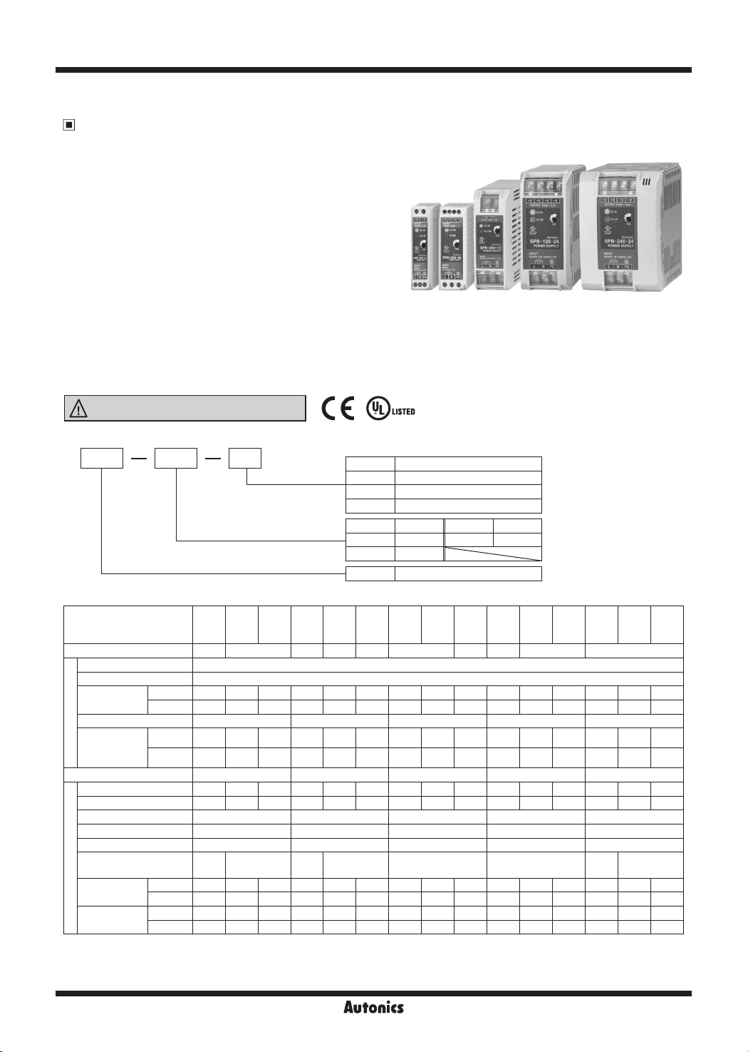
SPB Series
DIN rail mounting switching mode power supply
Features
● DIN rail type mount and screw mount methods
● Efcient power conversion
: High conversion efciency up to 92% with LLC circuit (SPB-240)
: Stable power supply with minimal noise and ripple
● Space efcient design
: Slim and compact size for maximum space efciency
: Uniform depth size (except SPB-015/030) for neat and
tidy installation
● Safety and user-friendly features
: Terminal protection cover (SPB-060/120/240)
: Easy wiring with rising clamp terminal (SPB-015/030)
: Inrush current prevention, output overcurrent
prevention, output overvoltage prevention,
output short-circuit protection, circuit overheating
SPB-015/030
Series
SPB-060
Series
SPB-120
Series
protection
: Low output voltage indicator (red LED), output indicator
(green LED)
● Output power: 15W, 30W, 60W, 120W, 240W
Please read “Safety considerations” in operation
manual before using.
Ordering Information
▣
SPB 120 24
Output voltage
Output power
Item
Specifications
▣
SPB
SPB
SPB
Model
Output power 15W 15.6W 25W 30W
Voltage 100-240VAC~ (permissible voltage: 85-264VAC~/120-370VDCᜡ)
Frequency 50/60Hz
Efciency
(typical)
Power factor
Current
Input condition
consumption
(typical)
Power factor correction circuit
Voltage
Current 3A 1.3A 0.65A 5A 2.5A 1.3A 5A 2.5A 1.3A 8A 5A 2.5A 20A 10A 5A
Voltage adjustment range
Input variation
Load variation Max. ±1% Max. ±1% Max. ±1% Max. ±1% Max. ±1%
Ripple&Ripple noise
Start-up time
(typical)
Output characteristics
Hold time
(typical)
※
1: It is for 100% load.
※
2: The output voltage adjuster (V.ADJ) should be used within voltage adjustment range.
※
3: It is for the rated input voltage 100-240VAC (85-264VAC), and 100% load.
※
4: It is for the rated input voltage 100-240VAC.
※
1
100VAC
240VAC
※
1
100VAC
※
1
240VAC
※
3
※
1
100VAC~500ms 550ms 650ms 600ms 550ms 550ms 520ms 550ms
240VAC
※
1
100VAC~24ms 25ms 25ms 20ms 15ms 15ms 15ms 14ms 15ms 98ms 75ms 87ms 33ms 36ms 25ms
240VAC
-015
-015
-05
-12
~ 77% 80% 83% 77% 82% 84% 81% 84% 85% 82% 85% 85% 87% 89% 89%
~ 76% 79% 82% 78% 83% 85% 83% 86% 87% 85% 88% 88% 90% 92% 92%
- - -
~ 0.35A 0.36A 0.34A 0.56A 0.63A 0.63A 1.24A 1.21A 1.19A 1.19A 1.49A 1.43A 2.76A 2.71A 2.73A
~ 0.19A 0.19A 0.19A 0.30A 0.35A 0.35A 0.66A 0.65A 0.64A 0.52A 0.61A 0.61A 1.14A 1.12A 1.13A
- - -
5VDCᜡ
12VDCᜡ24VDCᜡ5VDCᜡ
※
2
Max. ±10% Max. ±10% Max. ±5% Max. ±5% Max. ±5%
Max. ±0.5% Max. ±0.5% Max. ±0.5% Max. ±0.5% Max. ±0.5%
Max.
※1,※
4
Max. ±1%
±1.5%
~
550ms 550ms 650ms 600ms 550ms 550ms 530ms 550ms 400ms 400ms 400ms 400ms 45ms 56ms 45ms
~
190ms 190ms 190ms 130ms 110ms 110ms 100ms 110ms 108ms 97ms 43ms 86ms 33ms 36ms 25ms
-015
-24
SPB
-030
-05
Max.
±1.5%
5 5VDC
12 12VDC
24 24VDC
48 48VDC
015 15W 120 120W
030 30W 240 240W
060 60W
SPB Switching Mode Power Supply
SPB
SPB
SPB
SPB
SPB
SPB
SPB
-030
-030
-060
-060
-060
-12
-24
-12
31.2W
12VDCᜡ24VDCᜡ12VDCᜡ24VDCᜡ48VDCᜡ12VDCᜡ 24VDCᜡ 48VDCᜡ12VDCᜡ24VDCᜡ48VDC
Max. ±1% Max. ±1% Max. ±1%
-24
60W
-120
-48
-12
62.4W
96W 120W 240W
Min. 0.9 Min. 0.9
Built-in Built-in
1200ms 1200ms 1200ms 1200ms
-120
-24
SPB
-120
-48
SPB-240
SPB
-240
-12
Max.
±1.5%
75ms 87ms 75ms
Series
SPB
-240
-24
Max. ±1%
SPB
-240
-48
ᜡ
P-12
Page 2
DIN rail Mount Type Switching Mode Power Supply
Specifications
SPB
SPB
SPB
SPB
SPB
SPB
SPB
SPB
SPB
SPB
SPB
SPB
SPB
Model
Inrush current
protection
(typical)
Over-current protection
Over-voltage protection
Protection
Output low-voltage
indicate
100VAC~
240VAC~
-015
-015
-015
-030
-030
-030
-060
-060
-060
-120
-120
-05
-12
-24
-05
-12
-24
-12
-24
-48
-12
-24
-120
-48
7A 7A 7A 7A 7A 6A 13A 14A 10A 9A 11A 10A 8A 8A 8A
32A 30A 31A 29A 31A 29A 19A 17A 37A 37A 36A 37A 22A 25A 26A
※
4
105 to 160% 105 to 160% 105 to 160% 105 to 160% 105 to 160%
- - -
4.2V
9.6V
20.0V
4.2V
9.6V
20.0V
9.6V
±10%
±10%
±10%
±10%
±10%
±10%
±10%
20.0V
±10%
43.0V
±10%
16.0V
±10%
9.6V
±10%
30.0V
±10%
20.0V
±10%
58.0V
±10%
43.0V
±10%
Indicator Output indicator: Green LED, Output low-voltage indicator: Red LED
Insulation resistance Over 100MΩ (at 500VDC megger between all input terminals and output terminals)
Dielectric strength
3,000VAC 50/60Hz for 1 min (between all input terminals and output terminals)
1,500VAC 50/60Hz for 1 min (between all input terminals and F.G.)
Vibration 0.75mm amplitude at frequency 10 to 55Hz (for 1 min) in each X, Y, Z direction for 2 hour
Shock 300m/s² (approx. 30G) in each X, Y, Z direction for 3 times
EMS Conforms to EN61000-6-2
EMI Conforms to EN61000-6-4
Safety standards EN60950, EN50178
Ambient temp.
Environ
-ment
Ambient humi. 25 to 85%RH, storage: 25 to 90%RH
Input cable
※
5
-10 to 50℃, storage: -25 to 65℃ (surrounding air temp.: max. 40℃)
AWG24 to 19
(material: Cu)
AWG24 to 19
(material: Cu)
AWG21 to 19
(material: Cu)
AWG21 to 19
(material: Cu)
Terminal tightening torque 0.3 to 0.5N.m 0.3 to 0.5N.m 0.7 to 0.9N.m 0.7 to 0.9N.m 0.7 to 0.9N.m
Protection IP20 (IEC standard)
Approval
※
6
Weight
※
5: Refer to '
※
6: The weight includes packaging. The weight in parenthesis is for unit only.
※
Environment resistance is rated at no freezing or condensation.
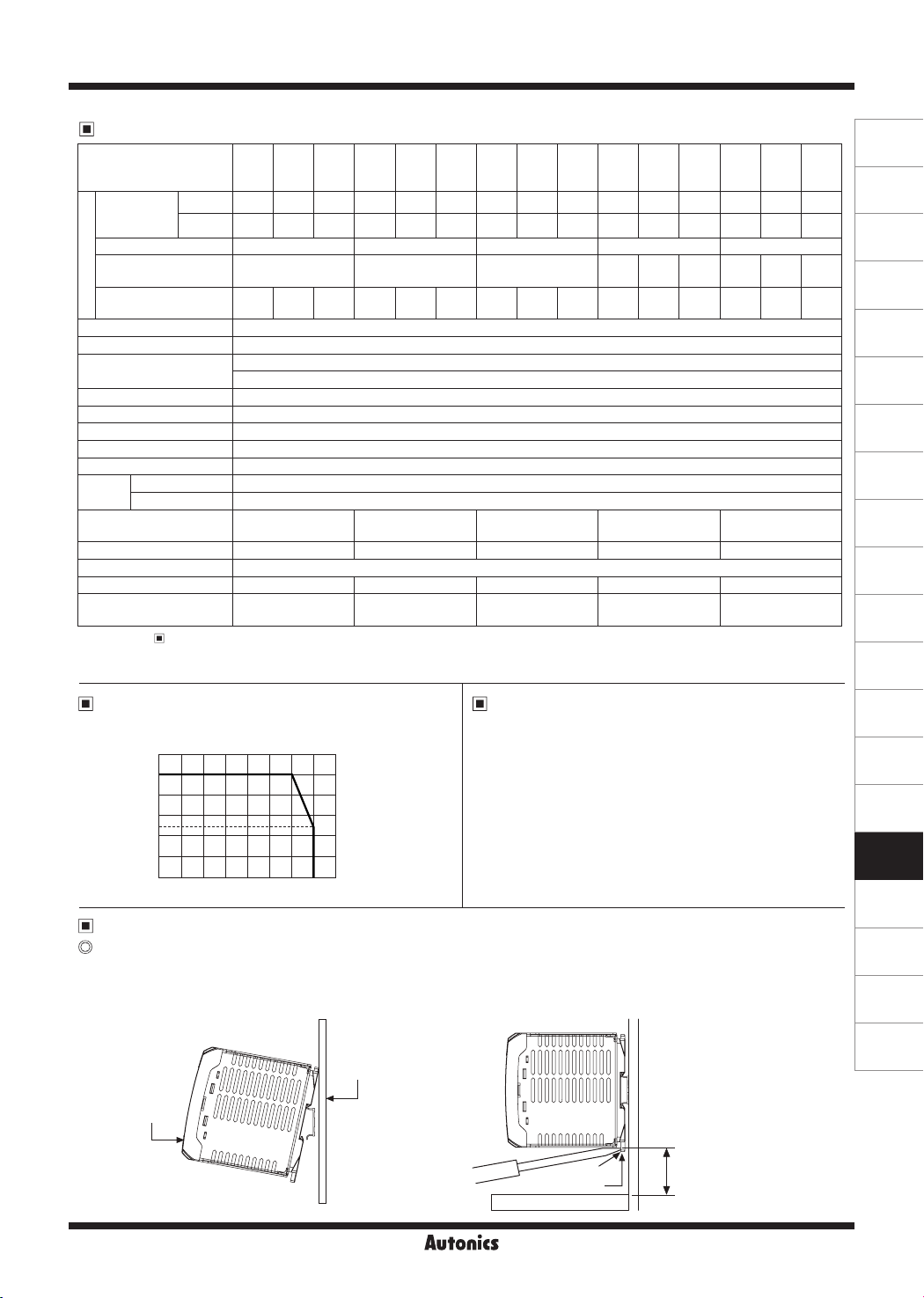
Output Deterating Curve By
Output Derating Curve By Ambient Temperature'.
Ambient Temperature
Load
ratio
100
[%]
80
60
50
40
20
0
-10 0 10 20 30 40 50 60 70
Approx. 202g
(approx. 129g)
Approx. 249g
(approx. 176g)
Approx. 347g
(approx. 274g)
Over-Heating Protection
Approx. 570g
(approx. 466g)
If the inner temperature of the switching element is around
140℃ by overheat, it stops switching operation and
becomes open state. Output voltage is not output.
Ambient
temperature
[℃]
Installation
DIN rail mounting
● Mounting to DIN rail
Put the unit on the part ⓐ of the rail before press it
to the direction ⓑ.
● Removing from DIN rail
Put a screw driver into the part ⓒ before push it
downward.
SPB
-240
-240
-12
-24
16.0V
30.0V
±10%
±10%
10.0V
20.0V
±10%
±10%
AWG18 to 16
(material: Cu)
Approx. 866g
(approx. 736g)
SPB
-240
-48
58.0V
±10%
43.0V
±10%
(A)
Photoelectric
Sensors
(B)
Fiber
Optic
Sensors
(C)
Door/Area
Sensors
(D)
Proximity
Sensors
(E)
Pressure
Sensors
(F)
Rotary
Encoders
(G)
Connectors/
Connector Cables/
Sensor Distribution
Boxes/Sockets
(H)
Temperature
Controllers
(I)
SSRs / Power
Controllers
(J)
Counters
(K)
Timers
(L)
Panel
Meters
(M)
Tacho /
Speed / Pulse
Meters
(N)
Display
Units
(O)
Sensor
Controllers
(P)
Switching
Mode Power
Supplies
(Q)
Stepper Motors
& Drivers
& Controllers
(R)
Graphic/
Logic
Panels
(S)
Field
Network
Devices
※
When mounting this unit on
ⓐ
the rail, place the unit at least
30mm above from the floor to
(T)
Software
remove it easily.
ⓑ
ⓒ
Rail hook
Min. 30mm
P-13
Page 3
SPB Series
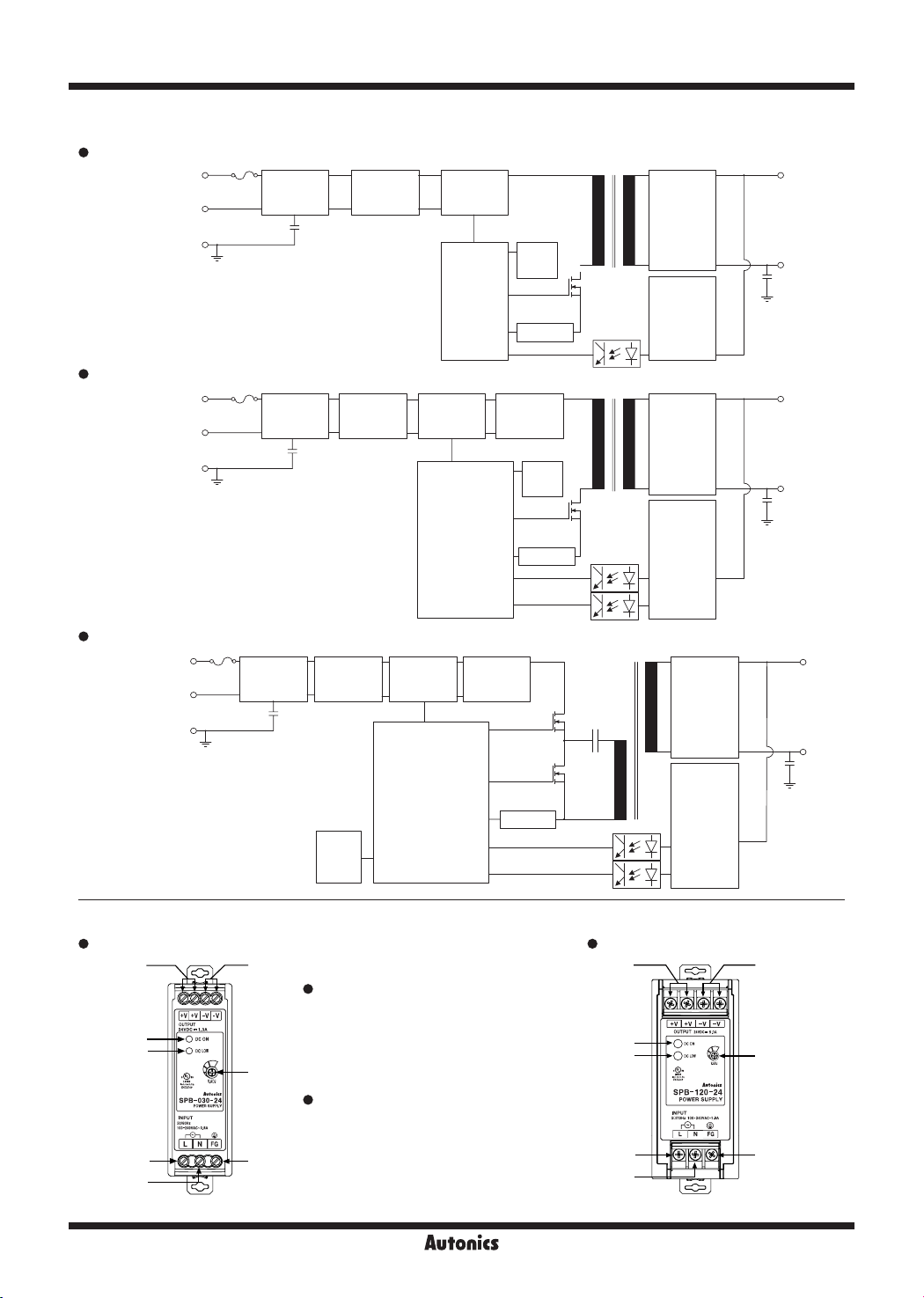
▣ Block Diagram
SPB-015/030/060 Series
Input
100-240VAC
50/60Hz
SPB-120 Series
Input
100-240VAC
50/60Hz
AC1(L)
AC1(N)
F.G.
AC1(L)
AC1(N)
F.G.
Input/
Noise lter
Input/
Noise lter
Inrush current
limit circuit
Rectier
circuit
Rectier
circuit
Control
circuit
Power factor
correction
circuit
Control
circuit
Auxiliary
power
Over load detect
Inrush current
limit circuit
Auxiliary
power
Over load detect
Rectier
circuit
Output
voltage
detection
Rectier
circuit
Output
voltage
detection
+
Output
-
+
Output
-
SPB-240 Series
Input
100-240VAC
50/60Hz
AC1(L)
AC1(N)
F.G.
Input/
Noise lter
Rectier
circuit
Auxiliary
power
Power factor
correction
circuit
Control
Circuit
Inrush current
limit circuit
Over load detect
Rectier
circuit
Output
voltage
detection
▣ Wiring Diagram/Unit Description
SPB-015/030 Series SPB-060/120/240 Series
21
Wiring Diagram
1. Output power [+V] terminal
2. Output power [-V] terminal
A
B
3. Input power [L] terminal
4. Input power [N] terminal
5. Frame ground [F.G.] terminal
C
Unit Description
A. Output (DC ON) indicator (green)
B. Output low voltage (DC LOW) indicator (red)
3
4
※
SPB-015/060 Series has an output power [+V] terminal (1) and an output power [-V] terminal (2).
C. Output voltage adjuster (V.ADJ)
5
1
A
B
3
4
+
Output
-
2
C
5
P-14
Page 4
DIN rail Mount Type Switching Mode Power Supply
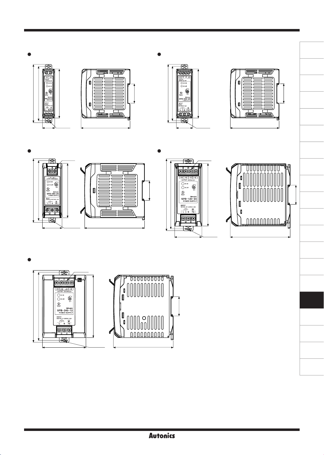
▣ Dimensions
SPB-015 Series
107
100
SPB-060 Series
117
110
SPB-240 Series
132
125
90
22.5 2-Ø4.2
5-M3.5
100
36 2-Ø4.2
80
7-M3.5
115
2-Ø4.2
(A)
SPB-030 Series
100
35.4
107
90
90
2-Ø4.2
30
90
(unit: mm)
35.4
SPB-120 Series
7-M3.5
110
110
35.4
132
125
50
35.4
115
2-Ø4.2
110
Photoelectric
Sensors
(B)
Fiber
Optic
Sensors
(C)
Door/Area
Sensors
(D)
Proximity
Sensors
(E)
Pressure
Sensors
(F)
Rotary
Encoders
(G)
Connectors/
Connector Cables/
Sensor Distribution
Boxes/Sockets
(H)
Temperature
Controllers
(I)
SSRs / Power
Controllers
35.4
(J)
Counters
(K)
Timers
(L)
Panel
Meters
(M)
Tacho /
Speed / Pulse
Meters
(N)
Display
Units
(O)
Sensor
Controllers
(P)
Switching
Mode Power
Supplies
(Q)
Stepper Motors
& Drivers
& Controllers
(R)
Graphic/
Logic
Panels
(S)
Field
Network
Devices
P-15
(T)
Software
Page 5
SPB Series
▣ Proper Usage
Cautions for operating
This product does not have the function for parallel or series operation.
The output current must be used within the rated specification.
If over-current is applied to the product, over-current protection is operating.
It causes shorten the life cycle of the product.
The output voltage must be used within the rated output specification.
For the product, which has the control function for over-voltage, if making the output voltage adjuster (V.ADJ) to over
rated voltage, the function starts to work.
This product has the function of over-heating protection.
The over-heating protection operates when the product has over-heating condition.
The product normally operates if the load is removed for over 5 minutes.
In case of the SPB-015/030/060, it does not have the harmonics suppression and power factor improvement circuit.
To improve harmonics suppression and power factor, install the additional device.
In case of the SPB-015/030/060, it uses condenser rectification, and power factor is within 0.4 to 0.6 range. To use a
abinet panel or a electric transformer, select input power capacity of this product as below formula.
Input apparent power [VA] =
This product is provided with a noise filter, but noise is variable according to operating conditions such as installation
environment and wiring.
When the inner fuse is damaged, replace the fuse of same specification.
Cautions for mounting
Mount this product on the surface of metal panel vertically for the reliability.
Please mount this product at a well-ventilated place in order to increase the heat radiation efficiency.
Mounting
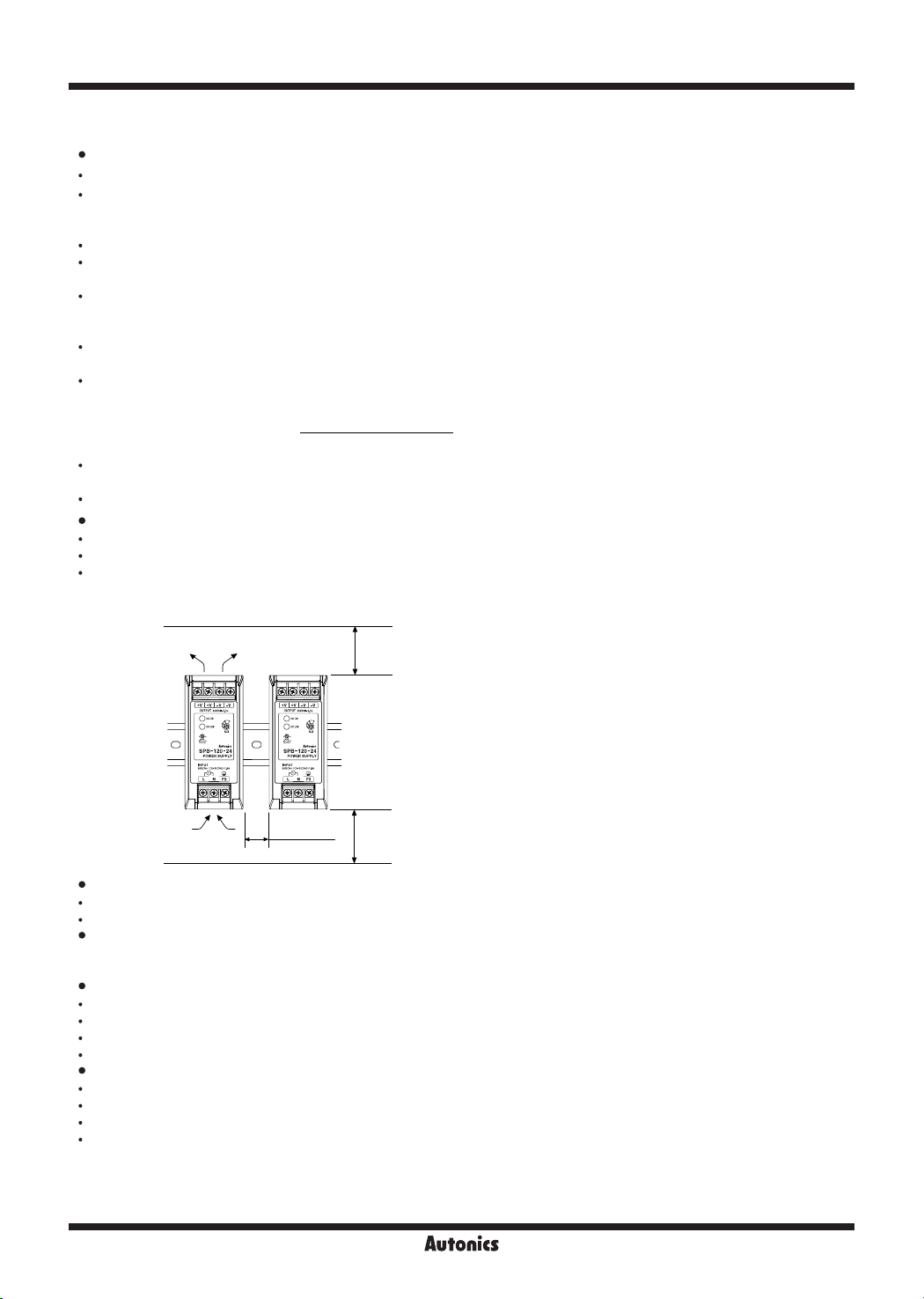
When installing more than two power supplies, min. 20mm distance is required to radiate heat effectively.
Assure min. 75mm distance of the upper or the lower product and mount the products as following figure.
Output active power [W]
Power factor×Efciency
Air ow
Air ow
Dielectric or insulation resistance test when this unit is installed in the control panel.
Separate the unit completely from a control panel circuit.
Short all terminals of the unit.
Caution for connecting the input power terminal
Connect input line(AC) to the input terminal correctly.
When you connect this to the other terminal, it may cause damage to the power supply.
Do not use the unit in the following environments.
Environments with high vibration or shock.
Environments with strong alkalis or acids.
Environments with exposure to direct sunlight.
Near machinery which produce strong magnetic force or electric noise.
This unit may be used in the following environments.
Indoors
Max. altitude: 2,000m
Pollution degree 2
Installation category II
Min. 20mm
Min. 75mm
Min. 75mm
P-16
 Loading...