

Page 1
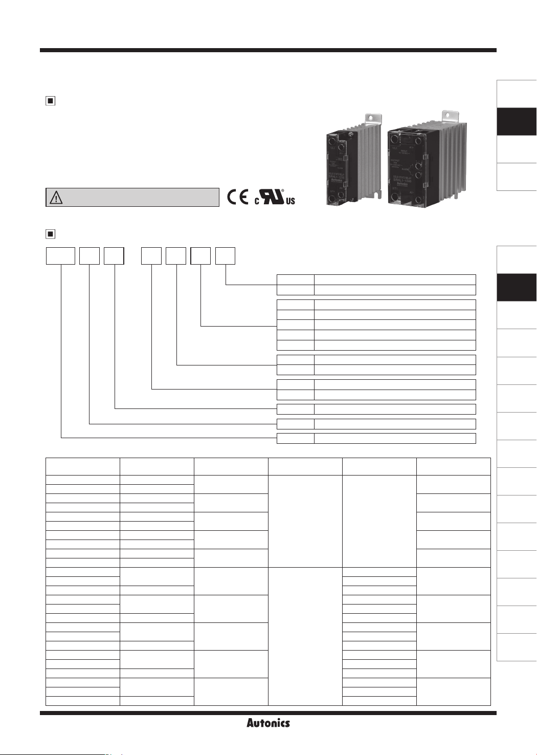
SRHL1 Series
Single-Phase, Integrated Heatsink Type SSR [Left-Right Terminal]
Features
● Zero cross turn-on, random turn-on models available
● Input indicator (green LED)
● Alarm function (overheat prevention)
- Rated load current 10A/15A/20A/25A: alarm indicator (red LED)
- Rated load current 40A: alarm indicator (red LED), alarm output
● DIN rail mount or panel mount installation
Please read “Safety Considerations”
in the instruction manual before using.
Ordering Information
SENSORS
CONTROLLERS
MOTION DEVICES
SOFTWARE
SRH 11L 4 40-
Function
Rated input current
(resistive load)
Rated load voltage
Rated input voltage
Control phase
Input/output terminal
Item
Model Rated input voltage Rated load current Rated load voltage Function
SRHL1-1210 10-30VDC
SRHL1-4210 90-240VAC
SRHL1-1215 10-30VDC
SRHL1-4215 90-240VAC
SRHL1-1220 10-30VDC
SRHL1-4220 90-240VAC
SRHL1-1225 10-30VDC
SRHL1-4225 90-240VAC
SRHL1-1240 10-30VDC
SRHL1-4240 90-240VAC
SRHL1-1410
10-30VDC
SRHL1-4410 90-240VAC
SRHL1-1415
10-30VDC
SRHL1-4415 90-240VAC
SRHL1-1420
10-30VDC
SRHL1-4420 90-240VAC
SRHL1-1425
10-30VDC
SRHL1-4425 90-240VAC
SRHL1-1440
SRHL1-1440R Random turn-on
10-30VDC
SRHL1-4440 90-240VAC
ᜡ
ᜠ
ᜡ
ᜠ
ᜡ
ᜠ
ᜡ
ᜠ
ᜡ
ᜠ
ᜡ
10A
15A Alarm indicator
20A Alarm indicator
25A Alarm indicator
40A
10A
ᜠ
ᜡ
15A
ᜠ
ᜡ
20A
ᜠ
ᜡ
25A
ᜠ
ᜡ
40A
ᜠ
No mark Zero cross turn-on
R Random turn-on
10 10A
15 15A
20 20A
25 25A
40 40A
2 24-240VAC
4 48-480VAC
1 10-30VDC
4 90-240VAC
1 Single-phase
L Left-Right terminal
SRH Solid State Relay (integrated heatsink type)
24-240VAC
ᜠ
Zero cross turn-on
Zero cross turn-on
Zero cross turn-on
Zero cross turn-on
Zero cross turn-on
Zero cross turn-on
48-480VAC
ᜠ
Zero cross turn-on
Zero cross turn-on
Zero cross turn-on
Zero cross turn-on
Zero cross turn-on
Alarm
(overheat prevention)
Alarm indicator
Alarm indicator
+Alarm output
Alarm indicatorSRHL1-1410R Random turn-on
Alarm indicatorSRHL1-1415R Random turn-on
Alarm indicatorSRHL1-1420R Random turn-on
Alarm indicatorSRHL1-1425R Random turn-on
Alarm indicator
+Alarm output
(J)
Temperature
Controllers
(K)
SSRs
(L)
Power
Controllers
(M)
Counters
(N)
Timers
(O)
Digital
Panel Meters
(P)
Indicators
(Q)
Converters
(R)
Digital
Display Units
(S)
Sensor
Controllers
(T)
Switching
Mode Power
Supplies
(U)
Recorders
(V)
HMIs
(W)
Panel PC
(X)
Field Network
Devices
Page 2
SRHL1 Series
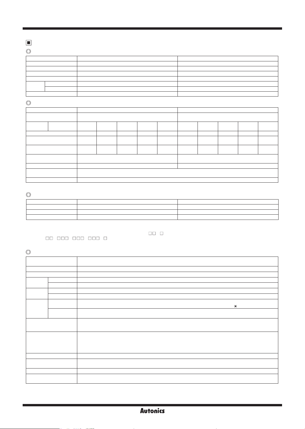
Specications
Input
Rated input voltage range
Allowable input voltage range
Max. input current 15mA 22mA
Pick-up voltage Min. 9VDC
Drop-out voltage Max. 1VDC
Turn-ON
time
Turn-o time Max. 0.5 cycle of load source + 1ms Max. 2 cycle of load source + 1ms
Zero cross turn-on
Random turn-on Max. 1ms
10-30VDC
9-32VDC
Max. 0.5 cycle of load source + 1ms Max. 2 cycle of load source + 1ms
ᜡ
ᜡ
ᜡ
ᜡ
Output
Rated load voltage range
Allowable load voltage
range
Rated load
current
Min. load current 0.15Arms 0.15Arms 0.2Arms 0.2Arms 0.5Arms 0.5Arms 0.5Arms 0.5Arms 0.5Arms 0.5Arms
Max. 1 cycle surge current
(60Hz)
Max. non-repetitive surge
current (I2t, t=8.3ms)
Peak voltage
(non-repetitive)
Leakage current (Ta=25℃) Max. 10mArms (240VACᜠ/60Hz) Max. 10mArms (480VACᜠ/60Hz)
Output on voltage drop
[Vpk] (max. load current)
Static o state dv/dt 500V/
※
1: AC-51 is utilization category at IEC 60947-4-3.
Resistive load
(AC-51)
24-240VACrmsᜠ (50/60Hz) 48-480VACrmsᜠ (50/60Hz)
24-264VACrmsᜠ (50/60Hz) 48-528VACrmsᜠ (50/60Hz)
※
10Arms 15Arms 20Arms 25Arms 40Arms 10Arms 15Arms 20Arms 25Arms 40Arms
1
160A 160A 250A 250A 400A 300A 300A 500A 500A 500A
130A2s 130A2s 300A2s 300A2s 910A2s 350A2s 350A2s 1000A2s 1000A2s 1000A2s
600V 1200V (Zero cross turn-on), 1000V (Random turn-on)
Max. 1.6V
Alarm output (overheat prevention)
Rated input voltage range
Load voltage Max. 30VDC
Load current Max. 50mA Max. 50mA
Turn-o time Max. 50ms Max. 100ms
※
Overheat prevention function: When SSR internal temperature is overheated, the load output is cut o to prevent internal device damage.
※
Alarm output is only for the rated load current 40A model (SRHL1- 40 ). In case of the rated load current 10A/15A/20A/25A models
(SRHL1- 10 / 15 / 20 / 25 ), the alarm indicator turns ON, regardless of alarm output.
※
To clear alarm, cut OFF the input signal during over alarm output return time at the rated ambient temperature.
10-30VDC
ᜡ
ᜡ
The alarm indicator turns ON and alarm output turns ON.
General specifications
Dielectric strength (Vrms)
Insulation resistance Over 100MΩ (at 500VDC megger) (input-output, input/output-case)
Indicator Input indicator: green LED, alarm indicator: red LED
Vibration
Shock
Environment
Input terminal connection,
alarm output terminal
connection
Output terminal
connection
Input terminal xed torque 0.75 to 0.95N·m
Output terminal
xed torque
Approval
Weight
1: The weight includes packaging. The weight in parenthesis is for unit only.
※
Environment resistance is rated at no freezing or condensation.
※
For wiring the terminal, round terminal must be used.
※
Mechanical 0.75mm amplitude at frequency of 10 to 55Hz (for 1 min) in each X, Y, Z direction for 1 hour
Malfunction 0.5mm amplitude at frequency of 10 to 55Hz (for 1 min) in each X, Y, Z direction for 10 min
Mechanical 300m/s2 (approx. 30G) in each X, Y, Z direction for 3 times
Malfunction 100m/s2 (approx. 30G) in each X, Y, Z direction for 3 times
Ambient
temperature
Ambient
humidity
※
1
• Input-output: 2500VAC 50/60Hz for 1 min
• Input/output-case: 4000VAC 50/60Hz for 1 min
-30 to 70℃, storage: -30 to 100
(The rated load current capacity is dierent depending on ambient temperature. Refer to ' SSR Derating Curve'.)
45 to 85%RH, storage: 45 to 85%RH
Min. 1×0.5mm2 (1×AWG20), max. 1×4mm2 (1×AWG12) or 2×1.5mm2 (2×AWG16)
• Rated load current 10A/15A/20A/25A:
min. 1×0.75mm2 (1×AWG18), max. 1×6mm2 (1×AWG10) or 2×2.5mm2 (2×AWG14)
• Rated load current 40A:
min. 1×1.5mm2 (1×AWG16), max. 1×16mm2 (1×AWG6) or 2×6mm2 (2×AWG10)
※
Use wires compliant with load current capacity to connect to the terminal.
• Rated load current 10A/15A/20A/25A: 1.0 to 1.35N·m
• Rated load current 40A: 1.6 to 2.2N·m
ᜢ ᜧ
• Rated load current 10A/15A/20A/25A: approx. 270g (approx.192g)
• Rated load current 40A: approx. 468g (approx. 372g)
℃
90-240VACrmsᜠ (50/60Hz)
85-264VACrmsᜠ (50/60Hz)
Min. 85VACrms
Max. 10VACrms
-
90-240VACrmsᜠ (50/60Hz)
Max. 30VDC
ᜠ
ᜠ
ᜡ
K-28 K-29
Page 3
Single-Phase, Integrated Heatsink Type SSR
[Left-Right Terminal]
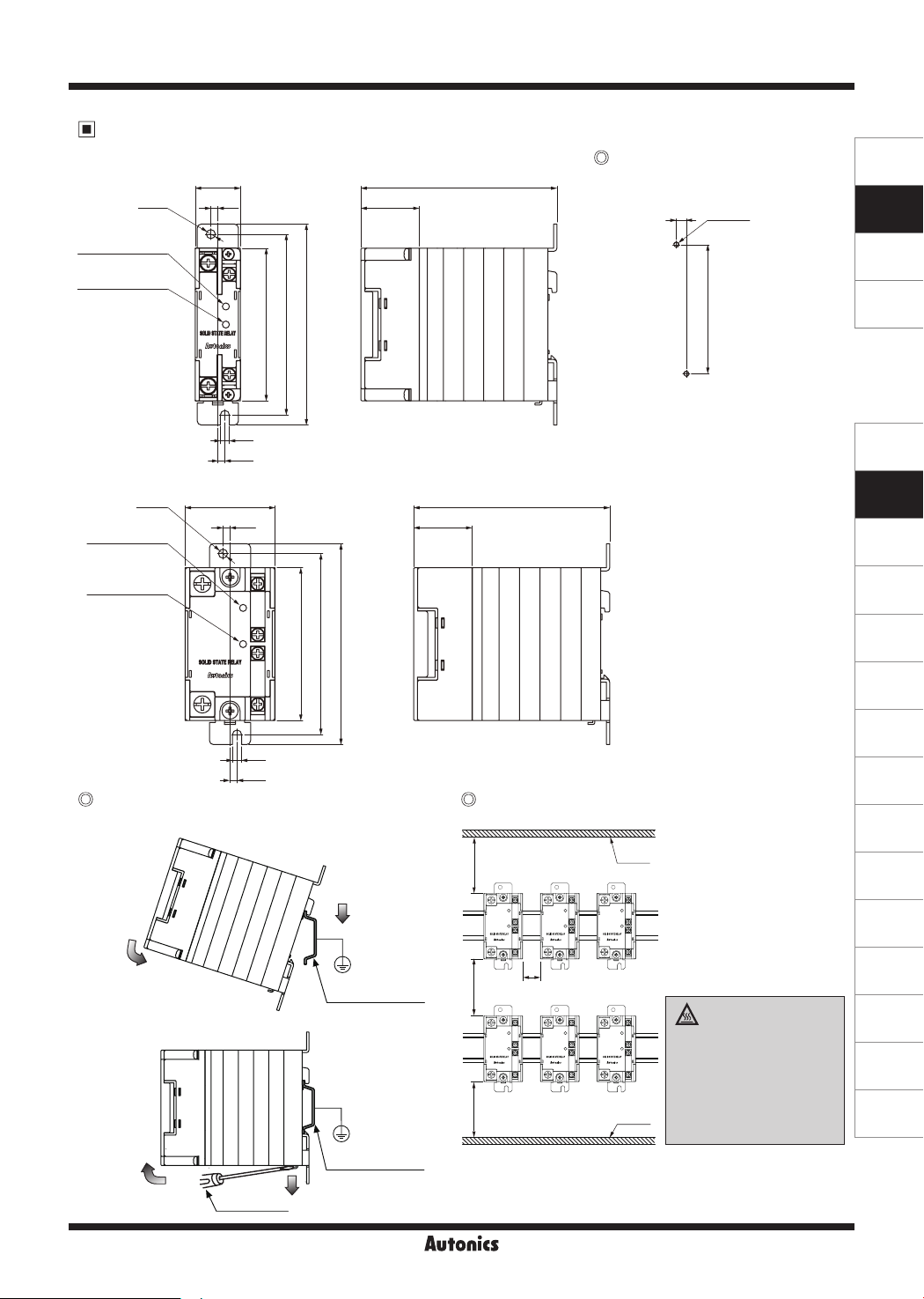
Dimensions
● Rated load current
Ø4.5
Input indicator
(green)
Alarm indicator
(red)
● Rated load current 40A
Ø4.5
Input indicator
(green)
Alarm indicator
(red)
10A/15A/20A/25A
22.5
3.5
4.5
3.5
44.8
3.5
Panel cut-out
SENSORS
97.6
(unit: mm)
29
7
2-M4
90
76
90
100
※
Screw tightening torque for mounting
: 1.8 to 2.5N.m
97.6
29
76
90
100
CONTROLLERS
MOTION DEVICES
SOFTWARE
(J)
Temperature
Controllers
(K)
SSRs
(L)
Power
Controllers
(M)
Counters
(N)
Timers
(O)
Digital
Panel Meters
4.5
3.5
DIN rail mounting Spacing
● DIN rail attachment
①
②
※
DIN rail must be grounded.
● DIN rail detachment
②
(-) driver
35mm DIN rail
35mm DIN rail
①
100 100100
(P)
Indicators
(Q)
Converters
(R)
Digital
Display Units
Panel
※
When installing multiple SSRs,
please keep space between
SSRs for heat radiation.
When installing SSRs
horizontally (input part and
output part on the same
height), please supply less
20
than 50% of the rated load
current.
High temperature
caution
(S)
Sensor
Controllers
(T)
Switching
Mode Power
Supplies
(U)
Recorders
(V)
HMIs
While supplying power to the
load or right after turning o
the power of the load, do not
(W)
Panel PC
touch the body and heat sink.
Panel
Failure to follow this instruction
may result in a burn due to the
high temperature.
(X)
Field Network
Devices
Page 4
SRHL1 Series
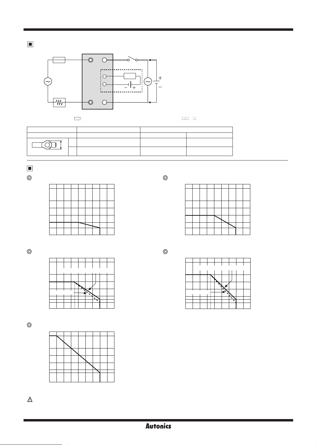
Connections
Rapid fuse
Load
power
source
(AC)
Load
※
Alarm output terminals are only for the rated load current 40A model (SRHL1- 40 ).
※
Use terminals of size specied below.
Terminal type
Rated load current
a
b
<Round>
SSR module
1/L1
A1+
Input
AL+
Output
SRHL1 Series
2/T1
Input, alarm output
Load
AL-
Alarm output
A2-
Output
Power
supply
(AC, DC)
10A, 15A, 20A, 25A, 40A 10A, 15A, 20A, 25A 40A
a Min. 3.5mm Min. 4.0mm Min. 5.0mm
b Max. 7.0mm Max. 9.0mm Max. 12.0mm
SSR Derating Curve
SRHL1-1210/1410/1410R/4210/4410 SRHL1-1215/1415/1415R/4215/4415
40
25
20
Load current [A]
15
10
6
0010 20 30 40 50 60 70 80 90
Ambient temperature [℃]
SRHL1-1220/1420/1420R/4220/4420
40
SRHL1-1220/1420/1420R/4220
25
20
Load current [A]
15
SRHL1-4420
10
8
6
0
0 10 20
30 40
50 60 70 80 90
35
Ambient temperature [℃]
SRHL1-1240/1440/1440R/4240/4440
40
25
20
Load current [A]
15
10
6
0010 20 30 40 50 60 70 80 90
Ambient temperature [℃]
SRHL1-1225/1425/1425R/4225/4425
40
SRHL1-1225/1425/1425R/4225
25
20
Load current [A]
15
SRHL1-4425
10
8
6
0
0 10 20
30 40
50 60 70 80 90
35
Ambient temperature [℃]
40
25
20
Load current [A]
15
10
9
0010 20 30 40 50 60 70 80 90
Since eectiveness of the heat radiation is decreased when multiple SSRs are installed closely, please supply less than
Ambient temperature [℃]
50% of the rated load current.
※
Above SSR derating curves obtained approval from the UL certication authority.
K-30 K-31
Page 5
Single-Phase, Integrated Heatsink Type SSR
[Left-Right Terminal]
Proper Usage
Cautions during use
1. Follow instructions in 'Cautions during use'. Otherwise, it may cause unexpected accidents.
2. 10-30VDC signal input should be insulated and limited voltage/current or Class 2, SELV power supply device.
3. Install the unit in the well ventilated place.
4. Ground to the heat sink, panel, or DIN rail.
Failure to follow this instruction may result in electric shock.
5. While supplying power to the load or right after turning o the power of the load, do not touch the body and heat sink.
Failure to follow this instruction may result in a burn due to the high temperature.
6. In order to protect the product from the short-circuit current of the load, use rapid fuse of which I2t is under the 1/2 of
SSR I2t. When short-circuited, replace the fuse to those of same specication with the used rapid fuse.
7. Install dummy resistance in parallel with the load, to keep the sum of current owing in the load and dummy resistance
being over SSR minimum load current.
8. When using random turn-on model for phase control, install noise lter between the load and the power of the load.
9. Do not use near the equipment which generates strong magnetic force or high frequency noise.
10. This unit may be used in the following environments.
Indoors (in the environment condition rated in 'Specications')
①
Altitude max. 2,000m
②
Pollution degree 2
③
Installation category III
④
SENSORS
CONTROLLERS
MOTION DEVICES
SOFTWARE
(J)
Temperature
Controllers
(K)
SSRs
(L)
Power
Controllers
(M)
Counters
(N)
Timers
(O)
Digital
Panel Meters
(P)
Indicators
(Q)
Converters
(R)
Digital
Display Units
(S)
Sensor
Controllers
(T)
Switching
Mode Power
Supplies
(U)
Recorders
(V)
HMIs
(W)
Panel PC
(X)
Field Network
Devices
 Loading...