

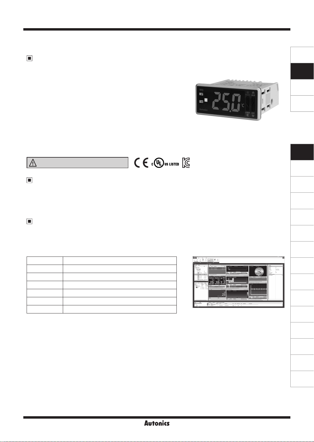
Refrigeration Temperature Controller
Features
Standard installation size for refrigeration and air-cooling panels
●●●
(W70.3×H28.2mm)
● Various compressor load current capacity: 5A, 16A, 20A
● Various user-friendly functions:
- Defrost sync function:
simultaneous defrost operation of multiple controllers (up to 6 units)
- RTC (Real Time Clock) function:
night mode operation and real-time defrost control
- Built-in alarm function
● Remote monitoring of real-time temperature and output control
(using TFD series remote display unit, sold separately)
● Communication output models available: RS485 (Modbus RTU)
● Parameter conguration via PC (RS485 communication)
- DAQMaster software included (comprehensive device management software)
● IP65 protection structure (IEC standard): front panel only
Please read “Safety Considerations”
in the instruction manual before using.
TF3 Series
SENSORS
CONTROLLERS
MOTION DEVICES
SOFTWARE
(J)
Temperature
Controllers
(K)
SSRs
Manual
● Visit our website (www.autonics.com) to download user manual and communication manual.
● User manual describes for specications and function, and communication manual describes for RS485 communication
(Modbus RTU protocol) and parameter address map data.
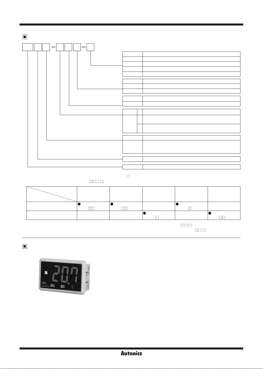
Comprehensive Device Management Program (DAQMaster)
● DAQMaster is comprehensive device management program. It is available for parameter setting, monitoring, and user
parameter group setting, parameter mask setting for only TF3 Series.
● Visit our website (www.autonics.com) to download user manual and comprehensive device management program.
< DAQMaster screen >< Computer specication for using software >
Item Minimum requirements
System IBM PC compatible computer with Intel Pentium Ⅲ or above
Operating system Microsoft Windows 98/NT/XP/Vista/7/8/10
Memory 256MB or more
Hard disk More than 1GB of free hard disk space
VGA 1024×768 or higher resolution display
Others RS-232 serial port (9-pin), USB port
(L)
Power
Controllers
(M)
Counters
(N)
Timers
(O)
Digital
Panel Meters
(P)
Indicators
(Q)
Converters
(R)
Digital
Display Units
(S)
Sensor
Controllers
(T)
Switching
Mode Power
Supplies
(U)
Recorders
(V)
HMIs
J-171
(W)
Panel PC
(X)
Field Network
Devices
TF3 Series
Ordering Information
TF
3 3 3 4 H T
Output
Number of input channels
Digits
Item
Option function
Compressor load capacity
Power supply
No-mark No option
S Synchronize defrost
※
2
T RS485 communication
※
3
R
※
3
A
※
1
G
A
H
1 24VAC 50/60Hz, 12-24VDC
4 100-240VAC 50/60Hz
1CH 1 Compressor output
1CH,
3CH
1
3
3 999 (3-digit)
TF Refrigeration Temperature Controller
RTC (real time clock)
RS485 communication+RTC (real time clock)
Compressor 20A 1a contact
Compressor 5A 1a contact
Compressor 16A 1c contact
Compressor+Defrost or Auxiliary
2
(alarm/evaporator-fan) output
Compressor+Defrost+Auxiliary
3
(alarm/evaporator-fan) output
1CH input (NTC or RTD) [temperature+digital input (DI)]
3CH input (NTC)
[inlet temperature+defrost temperature+
outlet temperature or digital input (DI)]
※
1: Only for 1CH input, compressor output model (TF31-1 G).
※
2: Only for 3CH input model (TF33- - ). Option function is varied by compressor load capacity and contact.
Compressor
load capacity & contact
Compressor 5A 1a contact
Compressor 16A 1c contact
※
3: Except compressor+defrost or auxiliary (alarm/evaporator-fan) output model (TF33-2
※
Only for 3CH input, compressor+defrost+auxiliary (alarm/evaporator-fan) output model (TF33-3
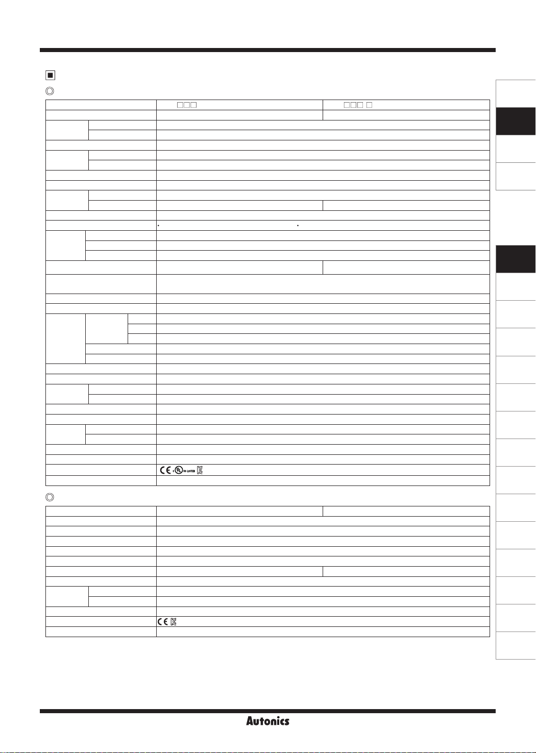
Remote Display Unit (TFD Series, Sold Separately)
Option function
Synchronize defrost
function
(TF33- A-S) (TF33- A-T)
- -
RS485
communication
RTC function
-
(TF33-3 H-R)
RS485
communication+
RTC function
(TF33-3 A-A)
-
- )
No option
-
(TF33- H)
- )
supports buzzer.
Remote display unit (TFD) displays current temperature or output
status of TF3 at remote place.
TFD cable is TFD-3: 3m, TFD-5: 5m.
Connect the phone-jack of remote display unit (TFD) to the data
loader port of TF3.
This unit is dedicated for TF3 Series and it does not directly
communicate with upper devices (PC, PLC, etc.)
If TFD communication with TF3 error occurs, TFD ashes display
component for 1 sec. Check the connection with TF3.
※
When connecting TFD to the data loader port of TF3, you cannot connect Autonics SCM-US (USB to Serial converter,
sold separately). for communication. Use SCM-US48I(USB to RS485 converter, sold separately), SCM-38I(RS232C to
RS485 converter, sold separately).
J-172
Refrigeration Temperature Controller
Specifications
TF3 Series
Model TF31- TF33- Number of channels 1CH 3CH
Power supply
Allowable voltage range 90 to 110% of rated voltage
Power
consumption
Display method 7 Segment LED method (red)
Character size (W×H) 9.4×19.3mm
Input type
Sampling period 500ms
Display accuracy
Control
output
Communication output
Digital input
Control method ON/OFF control
Hysteresis 0.5 to 5.0℃, 2 to 10℉ variable
Relay life
cycle
Memory retention Approx. 10 years (non-volatile memory method)
Insulation resistance Min. 100MΩ (at 500VDC megger)
Dielectric
strength
Noise resistance Square-wave noise by the noise simulator (pulse width: 1㎲) ±2kV R-phase and S-phase
Vibration 1.5mm amplitude at frequency of 10 to 55Hz (for 1 min) in each X, Y, Z direction for 2 hours
Environ
ment
Accessories Bracket: 2, NTC sensor (5kΩ): 1
Protection structure IP65 (front case)
Approval
Weight
Remote display unit [TFD]
Model
Power supply 3.3VDC
Power consumption Max. 1W
Display method 7 Segment LED method (red)
Communication method Serial (TTL Level), Half duplex
Communication cycle 100ms
Cable Ø2.5mm, 3m Ø2.5mm, 5m
Vibration 1.5mm amplitude at frequency of 10 to 55Hz (for 1 min) in each X, Y, Z direction for 2 hours
Enviornment
Protection structure IP67
Approval
Weight
※
1: The weight includes packaging. The weight in parentheses is for unit only.
※
Environment resistance is rated at no freezing or condensation.
AC power 100-240VACᜠ 50/60Hz
AC/DC power 24VACᜠ 50/60Hz, 12-24VDC
ᜡ
AC power Max. 8VA (100-240VACᜠ 50/60Hz)
AC/DC power Max. 5VA (24VACᜠ 50/60Hz), Max. 3W (12-24VDCᜡ)
NTC 5kΩ/10kΩ
RTD DPt100Ω
At room temp. (23℃±5℃): ±1℃±1 digit Out of room temp. range: ±2℃±1 digit
-
Compressor (COMP) 250VACᜠ 5A , 30VDCᜡ 5A, 1a / 250VACᜠ 16A, 24VDCᜡ 16A, 1c / 250VACᜠ 20A 1a
Defrost (DEF) 250VACᜠ 10A, 24VDCᜡ 10A, 1a
Auxiliary (AUX) 250VACᜠ 5A, 30VDCᜡ 5A, 1a
-
Contact input: ON max. 1㏀, OFF min. 100
㏀
RS485 communication output (Modbus RTU)
No contact input: ON residual voltage: max. 1V, OFF leakage current: max. 1mA, outow current: 4
Compressor
(COMP)
5A 1a Mechanical: 5,000,000 operations, Electrical: 50,000 operations (250VAC 5A)
16A 1c Mechanical: 20,000,000 operations, Electrical: 30,000 operations (250VAC 16A)
20A 1a Mechanical: 10,000,000 operations, Electrical: 100,000 operations (250VAC 20A)
Defrost (DEF) Mechanical: 20,000,000 operations, Electrical: 100,000 operations (250VAC 10A)
Auxiliary (AUX) Mechanical: 5,000,000 operations, Electrical: 50,000 operations (250VAC 5A)
AC power 3000VAC 50/60Hz for 1 min (between all terminals and case, power and input circuit)
AC/DC power 1000VAC 50/60Hz for 1 min (between all terminals and case, power and input circuit)
Ambient temperature -10 to 50℃, storage: -20 to 60
℃
Ambient humidity 35 to 85%RH, storage: 35 to 85%RH
※
1
● ● ●
Approx. 207g (approx. 105g)
TFD-3 TFD-5
ᜡ
Ambient temp. -10 to 50℃, storage: -20 to 60
℃
Ambient humi. 35 to 85%RH, storage: 35 to 85%RH
※
1
Approx. 77g (approx. 48g)
The weight is varied by model option.
㎂
SENSORS
CONTROLLERS
MOTION DEVICES
SOFTWARE
(J)
Temperature
Controllers
(K)
SSRs
(L)
Power
Controllers
(M)
Counters
(N)
Timers
(O)
Digital
Panel Meters
(P)
Indicators
(Q)
Converters
(R)
Digital
Display Units
(S)
Sensor
Controllers
(T)
Switching
Mode Power
Supplies
(U)
Recorders
(V)
HMIs
(W)
Panel PC
(X)
Field Network
Devices
J-173
TF3 Series
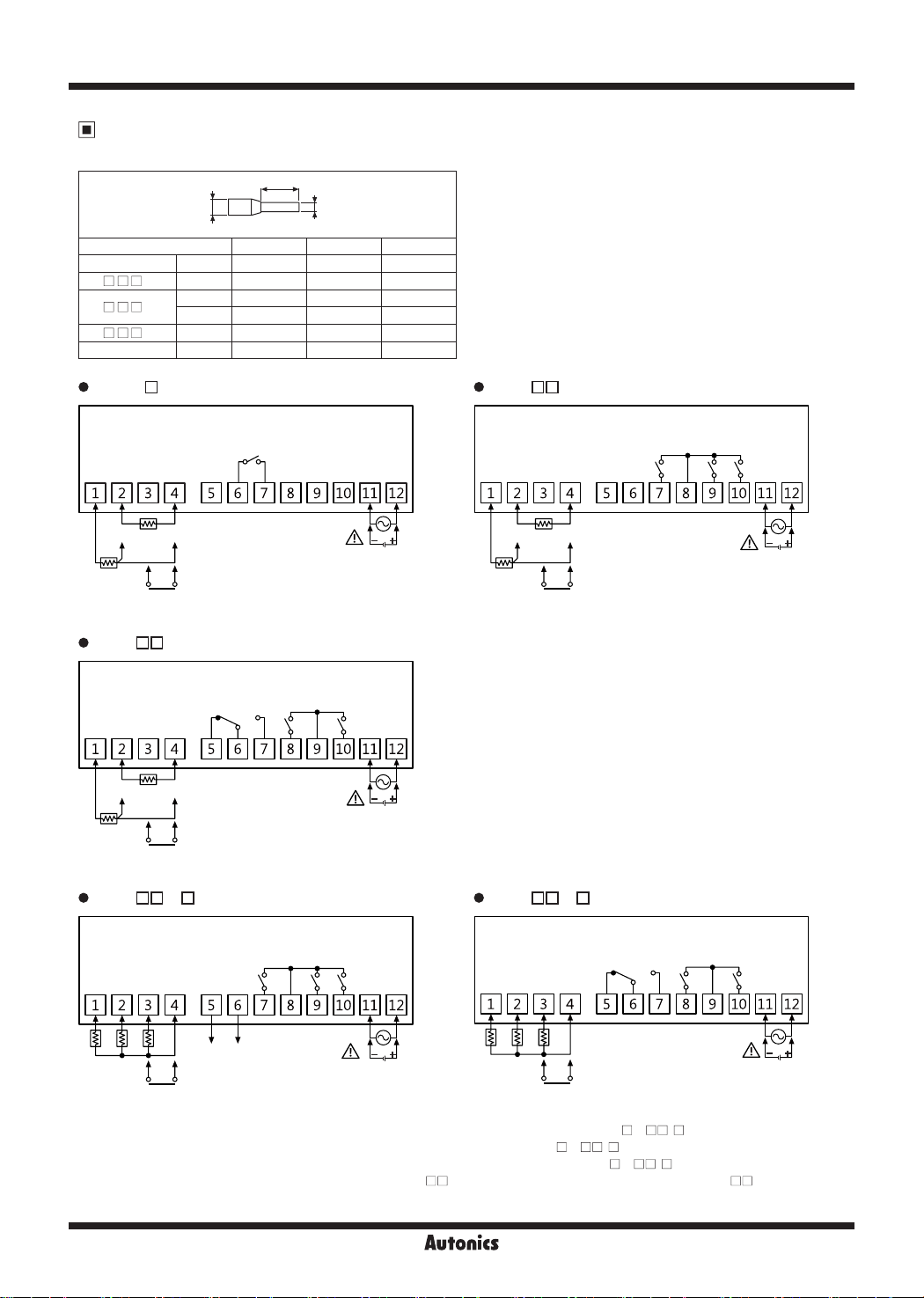
Connections
※
Use crimp terminals of size specied below.
a
c
<Crimp terminal>
Terminal number a b c
General 1 to 4 4 to 6mm Max. 1.7mm Max. 3.7mm
TF3 - H 5 to 10 6 to 8mm Max. 2.3mm Max. 4.5mm
TF3 - A
5 to 6 6mm Max. 1.9mm Max. 4.0mm
7 to 10 6 to 8mm Max. 2.3mm Max. 4.5mm
TF3 - G 6 to 7 6 to 8mm Max. 2.3mm Max. 4.5mm
General 11 to 12 6mm Max. 1.9mm Max. 4.0mm
TF31-1 G TF31- A
COMP OUT
250VAC 20A
RESISTIVE LOAD
b
COMP OUT
250VAC 5A
30VDC 5A
RESISTIVE LOAD
DEF OUT
250VAC 10A
24VDC 10A
RESISTIVE
※1
LOAD
AUX OUT
250VAC 5A
30VDC 5A
RESISTIVE
※2
LOAD
NTC 5K/10K
DPt100
SENSOR
DIGITAL INPUT
TF31- H
NTC 5K/10K
DPt100
SENSOR
DIGITAL INPUT
TF33- A-
S1 S2 S3 COM
COMP OUT
250VAC 16A
24VDC 16A
RESISTIVE LOAD
COMP OUT
250VAC 5A
30VDC 5A
RESISTIVE LOAD
DEF OUT
250VAC 10A
24VDC 10A
RESISTIVE
※1
LOAD
DEF OUT
250VAC 10A
24VDC 10A
RESISTIVE
※1
LOAD
SOURCE
100-240VAC 50/60Hz,
24VAC 50/60Hz,
12-24VDC
AUX OUT
250VAC 5A
30VDC 5A
RESISTIVE
※2
LOAD
SOURCE
100-240VAC 50/60Hz,
24VAC 50/60Hz,
12-24VDC
AUX OUT
250VAC 5A
30VDC 5A
RESISTIVE
※2
LOAD
NTC 5K/10K
DPt100
SENSOR
DIGITAL INPUT
TF33- H-
S2 S3 COM
S1
COMP OUT
250VAC 16A
24VDC 16A
RESISTIVE LOAD
DEF OUT
250VAC 10A
24VDC 10A
RESISTIVE
※1
LOAD
SOURCE
100-240VAC 50/60Hz,
24VAC 50/60Hz,
12-24VDC
AUX OUT
250VAC 5A
30VDC 5A
RESISTIVE
※2
LOAD
A+ B-
NTC 5K/10K
SENSOR
DIGITAL INPUT
※
1: Only for compressor+defrost or auxiliary (alarm/evaporator-fan) output model (TF3 -2 - ),
SYNCHRONIZE
※
3
/RS485
SOURCE
100-240VAC 50/60Hz,
24VAC 50/60Hz,
12-24VDC
NTC 5K/10K
SENSOR
DIGITAL INPUT
compressor+defrost+auxiliary (alarm/evaporator-fan) output model (TF3 -3 - ).
※
2: Only for compressor+defrost+auxiliary (alarm/evaporator-fan) output model (TF3 -3 - ).
※
3: Only for synchronize defrost function model (TF33- A-S), or RS485 communication model (TF33- A-T/A).
J-174
SOURCE
100-240VAC 50/60Hz,
24VAC 50/60Hz,
12-24VDC

Dimensions
TF3 Series
Refrigeration Temperature Controller
(unit: mm)
77
5.5
74.3
SENSORS
CONTROLLERS
NTC sensor (5kΩ)
Max. 5
6±0.2
Max. 15
Panel cut-out
B
A
2000±50
C
AWG22
TPE lead wire
Soldering
D
35
28
Bracket
3.3
4
46
37.5
40.5
5±1
Size
Series
A B C D
TF3 Min. 100
TFD Min. 65 Min. 40 45.7
※
1. When connecting remote display unit (TFD), or SCM-US, Min. 120
12
23.9
※
1
Min. 55 70.3
+ 0.7
0
+ 0.6
0
(unit: mm)
+ 0.5
28.2
0
+ 0.3
25.4
0
MOTION DEVICES
SOFTWARE
(J)
Temperature
Controllers
(K)
SSRs
(L)
Power
Controllers
(M)
Counters
(N)
Timers
(O)
Digital
Panel Meters
(P)
Indicators
Sold Separately
TFD
52
Communication converter
SCM-WF48
( Wi-Fi to RS485·USB wireless
communication converter)
3
12
31.5
SCM-US48I
(USB to RS485 converter)
25
Ø2.5,
3m or 5m
SCM-38I
(RS232C to RS485 converter)
SCM-US
(USB to Serial converter)
J-175
(Q)
Converters
(R)
Digital
Display Units
(S)
Sensor
Controllers
(T)
Switching
Mode Power
Supplies
(U)
Recorders
(V)
HMIs
(W)
Panel PC
(X)
Field Network
Devices
TF3 Series
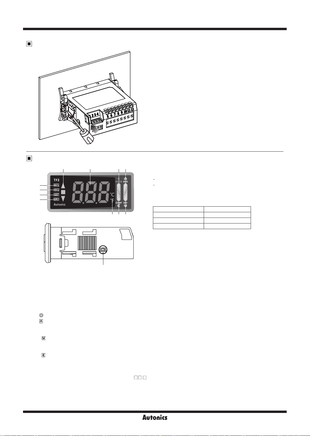
Product Mounting
Insert the unit into a panel, fasten the bracket by
(-) driver
Unit Description
1 8 92
3
4
5
6
7 11 10
12
4. Defrost (DEF) output indicator (green):
Turns ON for defrost output. Flashes for defrost delay operation.
Turns ON for 2 sec and OFF for 1 sec for manual defrost or Power ON defrost.
5. Evaporator-fan (FAN) output indicator (green):
Turns ON for evaporator-fan output. Flashes for delay operation of evaporator-fan output.
6. Auxiliary (AUX) output indicator (green):
7. Unit indicator (red):
8. (MODE) key:
9. (AUX) key:
Used for entering SV setting group or changing setting value.
Hold the key over 3 sec to select active/inactive auxiliary output in RUN mode.
10. (DEF) key:
Used for entering SV setting group or changing setting value.
Hold the key over 3 sec to execute/stop manual defrost in RUN mode.
11. (COMP) key:
Used for entering SV setting group, changing setting value, moving digits.
Hold the key over 3 sec to active/inactive compressor output in RUN mode.
When buzzer alarm occurs, press the key once to stop the sound. (Only for 3CH input, compressor+defrost+auxiliary
(alarm/evaporator-fan) output model (TF33-3 - ) supports buzzer.
Buzzer [
12. Data loader port:
BUZ
It is for displaying TF3 data at remote display unit (TFD) by connecting phone-jack.
In other case, for connecting Autonics SCM-US (USB/Serial converter, sold separately),
it is a PC loader port of serial communication for parameter setting or monitoring by PC.
Displays temperature unit set at temperature unit [
Used for entering parameter setting group, returning RUN mode, moving parameter or saving SV.
] of parameter 1 group is set as [ON])
pushing with tools with a (-) driver.
1. Present value (PV) display component (red):
RUN mode: Displays present value (PV).
Setting mode: Displays parameter and setting value.
2. Deviation indicator (■: green, ▼/▲: red):
Displays deviation of present value (PV) based on setting
value (SV).
PV deviation temperature Deviation display
More than 1.8℃
Within ±1.8
Less than -1.8
3. Compressor (COMP) output indicator (green):
Turns ON for compressor output. In case of compressor
protection operation and output does not turn ON,
it ashes. When operating compressor continuously, it turns ON
for 2 sec, and turns OFF for 1 sec.
Turns ON for alarm output. Flashes for delay operation of alarm output.
℃
℃
▲
indicator turns ON
■
indicator turns ON
▼
indicator turns ON
] of parameter 1 group.
UNT
J-176
Refrigeration Temperature Controller
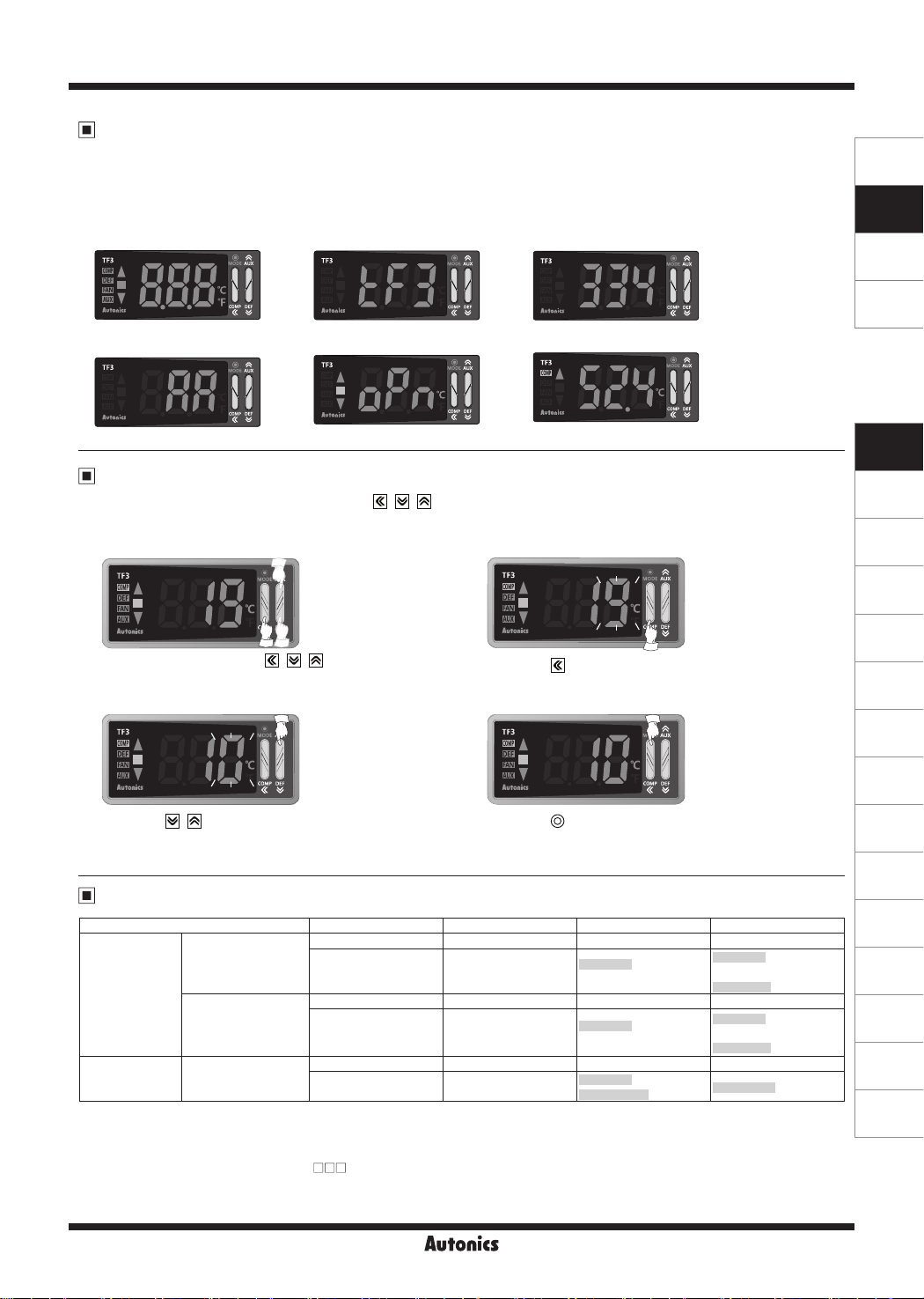
Front Panel Display When Power Is On
When power supplies to the unit, whole display part flashes approx. 1 sec. The display part displays model specification (no.
of input CHs, output, power supply, compressor load capacity, option function), flashes input type twice and the unit returns
to RUN mode to operate.
Model specification display is same as the unit model name. (E.g.: TF33-34A-A model)
SENSORS
CONTROLLERS
1. Whole display part
4. Compressor load capacity/
Option function
2. Series 3. No. of input CHs/Output/Power supply
5. Run mode
Sensor input error Normal operation
SV Setting
You can set the temperature to control with the , , keys.
Set range is within SV low-limit value [
] to SV high-limit value [
LSV
E.g.) In case of changing SV from 19℃ to 10℃
1 2
Press any key among the , , in RUN mode
to enter into SV setting mode. Last digit (100 digit)
on SV display part ashes.
3 4
].
HSV
Press the key to move digit.
(100→ 10¹→ 10²→10³→ 100)
MOTION DEVICES
SOFTWARE
(J)
Temperature
Controllers
(K)
SSRs
(L)
Power
Controllers
(M)
Counters
(N)
Timers
(O)
Digital
Panel Meters
(P)
Indicators
Press the , key to raise
or lower the set value. (9 → 0)
Press the (MODE) key to save the set value.
(If there is no additional key operations in 3 sec,
the changed SV is automatically saved.)
Input Type and Range
Input type Decimal point Display method Temperature range (℃) Temperature range (℉)
1
NTC 5kΩ
Thermistor
(NTC)
NTC 10kΩ
※
1
RTD
※
TF3 Series displays only 3 digits. If PV decimal number of shaded temperature range is out of 3 digit, TF3 does
DPt 100Ω
0.1
1
0.1
1
0.1
N%H
N%L
N!H
N!L
DpH
DpL
-40 to 99 -40 to 212
-40 to -20
-19.9 to 99.9
-40 to -20
-19.9 to 99.9
100 to 212
-40 to 99 -40 to 212
-40 to -20
-19.9 to 99.9
-40 to -20
-19.9 to 99.9
100 to 212
-99 to 99 -148 to 212
-99 to -20
-19.9 to 99.9
※
2
-148 to 212
not display the numbers below decimal point. You can check it at the comprehensive device management program
(DAQMaster) by communicating via PC.
※
1: Only for 1CH input model (TF31- ).
※
2: If PV with "-" sign is over 3 digits (e.g.: -99.9), the numbers below decimal point does not display.
You can check it at the comprehensive device management program (DAQMaster) by communicating via PC.
J-177
(Q)
Converters
(R)
Digital
Display Units
(S)
Sensor
Controllers
(T)
Switching
Mode Power
Supplies
(U)
Recorders
(V)
HMIs
(W)
Panel PC
(X)
Field Network
Devices

TF3 Series
Parameter Group
RUN mode
Press any key among
, , once
※
1
PS PSPS
SV setting
[SV]
Saved automatically
after 3 sec
Monitoring time [
Max. value [
Min. value [
※
Display selection
[
]
DpT
MoT
1.5 sec
]
hPK
]
lPK
1.5 sec
2 sec
[
PAU
※
1
When PW is validWhen PW is validWhen PW is valid
Parameter 1 group
[
BUZ
PA1
ㅑINT
]
]
]
VtR
]
UNT
]
Ib1
]
Ib2
]
Ib3
]
DsT
]
sDA
]
AUX
]
※
2
]
Input type [
Input sensor 2 ON/OFF [S2]
Input sensor 3 selection [S3]
Virtual temperature rate [
Temperature unit [
Input correction 1 [
Input correction 2 [
Input correction 3 [
Delay display period [
Defrost/auxiliary output [
Auxiliary output [
Buzzer [
1
Parameter user group
]
User parameter 0
1.5 sec 1.5 sec
User parameter 1 to 29
※
1. [PS] parameter appears only when password is set.
The default password is [
password code appears. Press any key among the , ,
keys to return to password entering window. Press the
(MODE) key to return to RUN mode.
If you forget password, contact Autonics after checking
password code.
※
2. It appears when setting user parameter group in the
comprehensive device management program (DAQMaster).
※Press the
※
Hold the (MODE) key for 1.5 sec while in setting mode to move to
the parameter group.
※
Hold the (MODE) key for 3 sec while in setting mode to return
RUN mode.
※
Press the (MODE)key at the last parameter of each parameter
group, it moves to that parameter group name. You can move to
other groups with , keys.
※
If there is no additional key operation within 30 sec after entering
into setting mode, it will be automatically returned to RUN mode and
previous setting value will be remained.
※
The shaded parameters are displayed when user level [
parameter 5 group is set as standard level [
(MODE) key after changing the setting to save the SV.
000
]. If password is not valid, the
STD
].
J-178
USR
] of
3 sec 3 sec

Refrigeration Temperature Controller
3sec
SENSORS
CONTROLLERS
MOTION DEVICES
Parameter 2 group
[
]
PA2
Comp. output mode [
OFT
]
Parameter 3 group
[
]
PA3
Defrost method & operation [
Parameter 4 group
]
Alarm operation mode [AL]
DEF
[
PA4
]
1.5sec 1.5sec 1.5sec 1.5sec
Hysteresis [
Oset [
SV high-limit [
SV low-limit [
Night mode [
Night mode SV correction [
Night mode hysteresis [
Night mode oset [
Night mode start hour [
Night mode start min [
Night mode end hour [
Night mode end min [
Temperature monitoring [
Comp. start-up delay time [
Comp. min. operation cycle [
Comp. restart delay time [
Comp. min. operation time [
OFS
HYS
]
HSV
LSV
nMD
]
]
]
]
nSV
nHY
]
nOF
nSH
]
nSM
]
nEH
]
nEM
eMO
SDL
CYC
RDL
ONT
Comp. continuous operation [CC]
Alarm delay time after
continuous operation [
AdC
]
Comp. operation cycle when
sensor break [
CLE
]
Comp. duty rate when
sensor break [
DUT
]
Defrost cycle [
Real-time defrost cycle [
Real-time defrost cycle 1: hour [
Real-time defrost cycle 1: min [
]
Real-time defrost cycle 8: hour [
]
Real-time defrost cycle 8: min [
Defrost time [
]
Pump down delay time [
Defrost end delay time [
Defrost end temperature [
Defrost hysteresis [
]
Defrost when power ON [
]
Defrost delay when power ON/
manual defrost [
]
Defrost group [
]
Parameter copy [
]
Prior defrost selection [
Defrost time unit [
Alarm delay after defrost/
door open [
Temperature display during
defrosting [
AdD
tDE
DIN
...
ㅑDET
dDE
dGR
]
]
]
]
pDC
uDE
dHY
]
]
rDI
DH1
DM1
DH8
DM8
Alarm option [
]
Alarm high-limit deviation [
]
Alarm low-limit deviation [
Alarm hysteresis [
]
Alarm ON delay time [
Alarm OFF delay time [
]
External alarm delay time [
]
AlT
]
aHY
]
aON
aOF
AlH
AlL
eAD
]
]
]
]
]
Alarm output method [aN]
PdD
DrT
EDT
]
pDE
Evaporator-fan operation [
]
Evaporator-fan control
]
temperature [fT]
]
Evaporator-fan hysteresis [
Evaporator-fan mode [
]
Evaporator-fan start-up
delay time [
pDR
]
FAN
fTY
fHY
]
]
]
]
]
dPR
]
Parameter 5 group
[
]
PA5
Current hour [
Current minute [
CUH
CUM
]
]
Digital input [DI]
Loop break alarm
monitoring time [
Comm. address [
Comm. speed [
Comm. parity bit [
Comm. stop bit [
LBA
BPS
STP
ADR
PRT
]
]
]
]
]
Comm. response wait time [
Comm. write [
User level [
SV setting group lock [
Front key lock [
PA 0 group lock [
PA user group lock [
PA 1 group lock [
PA 2 group lock [
PA 3 group lock [
PA 4 group lock [
PA 5 group lock [
Password [
USR
PWD
COW
lDK
]
]
]
lP0
lP1
lP2
lP3
lP4
lP5
lSV
]
]
lPU
]
]
]
]
]
RwT
]
SOFTWARE
(J)
Temperature
Controllers
(K)
SSRs
(L)
Power
Controllers
(M)
Counters
(N)
Timers
]
(O)
Digital
Panel Meters
]
(P)
Indicators
(Q)
Converters
(R)
Digital
Display Units
(S)
Sensor
Controllers
(T)
Switching
Mode Power
Supplies
(U)
Recorders
(V)
HMIs
3 sec 3 sec 3 sec 3 sec
J-179
(W)
Panel PC
(X)
Field Network
Devices

TF3 Series
Parameter 1 Group
3 sec
'PS
PW code appears
at SV display part
for wrong PW
RUN mode
1
※
S
Password input
'PS
When
PW
is wrong
Parameter 1 group
PA1
Input type
Input sensor 2 ON/OFF
2 sec
When PW is correct
+ 1 time
S
S
S2
1. S: Press any key among , , keys.
※
After entering setting mode, hold the (MODE) key anytime for 3 sec to return to RUN mode.
※
After entering setting mode, hold the (MODE) key anytime for 1.5 sec to go to the concerned
※
group name.
If you press the (MODE) key after changing the set value of the parameter the set value will
※
be stored.
Shaded parameters are for standard-level users, the others are for high-level users.
※
(You can set the user level [
This parameter might not be displayed depending on other parameter settings or model
※
specications.
S
000
NsH NsL DpLINT
OFF
ON
] in parameter 5 group).)
USR
Setting range: Refer to '▣ input type and
When changing input type, SV,
※
lPK, Ib1
LSV, nSV, nHY, EDT, dHY, AlH, AlL,
aHY, fT, fHY
reset.
range'.
,
,
Ib2
Ib3
parameter values are
,
HYS, OFS
hPK
,
HSV,
,
Input sensor 3 selection
S3
Virtual temperature rate
VtR
Temperature unit
UNT
Input correction 1
Ib1
Input correction 2
Ib2
Input correction 3
Ib3
Delay display period
DsT
Defrost/
auxiliary output
sDA
S
DI TS
S
S
S
S
S
S
S
0
?C ?F
0
0
0
)5
DEF AUX
Setting range: 0 to 100%
Appears only when input sensor 3
※
selection [
] is set as [TS].
INT
When changing temperature unit,
※
lPK, Ib1
LSV, nSV, nHY, EDT, dHY, AlH, AlL,
aHY, fT, fHY
Setting range: -40 to 40℃/
Setting range: -40 to 40℃/
Appears only for 3CH input model.
※
Setting range: 0.5 to 10.0 sec
Appears only for compressor+defrost or auxiliary
※
(alarm/evaporator-fan) output model.
Appears only for 3CH input model.
※
,
,
Ib2
,
Ib3
HYS, OFS, HSV,
parameter values are reset.
℉
℉
hPK
,
J-180
Auxiliary output
AUX
Buzzer
BUZ
Appears only for compressor+defrost or
S
OFF
S
ON
FAN ALM
Only for 3CH input, compressor+defrost+auxiliary
OFF
※
(alarm/evaporator-fan) output model supports buzzer.
※
auxiliary (alarm/evaporator-fan)
output model, compressor+defrost+auxiliary
(alarm/evaporator-fan).

Parameter 2 Group
3 sec
'PS
PW code appears
at SV display part
for wrong PW
RUN mode
1
※
S
Password input
When
PW
is wrong
Parameter 2 group
2 sec
'PS
When PW is correct
+ 2 times
PA2
Comp. output
mode
S
Refrigeration Temperature Controller
1. S: Press any key among , , keys.
※
After entering setting mode, hold the (MODE) key anytime for 3 sec to return to RUN mode.
※
After entering setting mode, hold the (MODE) key anytime for 1.5 sec to go to the concerned
※
group name.
If you press the (MODE) key after changing the set value of the parameter the set value will
※
be stored.
Shaded parameters are for standard-level users, the others are for high-level users.
※
(You can set the user level [
This parameter might not be displayed depending on other parameter settings or model
※
specications.
S
000
C HOFT
] in parameter 5 group).)
USR
When changing compressor output mode,
※
CLE, DUT
parameter values are reset.
SENSORS
CONTROLLERS
MOTION DEVICES
SOFTWARE
(J)
Temperature
Controllers
Hysteresis
HYS
Oset
OFS
SV high-limit
HSV
SV low-limit
LSV
Night mode
nMD
Night mode
SV correction
nSV
Night mode
hysteresis
nHY
Night mode
oset
nOF
(K)
]in
SSRs
(L)
Power
Controllers
(M)
Counters
(N)
Timers
(O)
Digital
Panel Meters
(P)
Indicators
(Q)
Converters
(R)
Digital
Display Units
(S)
Sensor
Controllers
(T)
Switching
Mode Power
Supplies
(U)
Recorders
(V)
HMIs
S
S
S
99
S
-40
S
S
S
S
Setting range: 1 to 5℃ (0.5 to 5.0℃), 2 to 10℉ (2.0 to 10.0℉)
1
Setting range: 0 to 5℃ (0.0 to 5.0℃), 0 to 10℉ (0.0 to 10.0℉)
0
Setting range: (
When changing SV high-limit value and SV >
※
+1digit) to high-limit value of input type
LSV
Setting range: low-limit value of input type to (
When changing SV low-limit value and SV <
※
TIN DIOFF
Setting range: -20 to 20℃ (-20 to 20.0℃)/
1
Setting range: 1 to 5℃ (0.5 to 5.0℃),
1
Setting range: 0 to 5℃ (0.0 to 5.0℃),
0
-50 to 50℉ (-50 to 50.0℉)
2 to 10℉ (2.0 to 10.0℉)
0 to 10℉ (0.0 to 10.0℉)
HSV, SV
HSV
LSV, SV
is reset as
HSV
-1digit)
is reset as
Appears for RTC function
※
LSV
model or when digital
input [DI] is set as [
parameter 5 group.
Does not appear when night
※
mode [
[
OFF
].
nMD
] is set as
.
.
nMD
Night mode
start hour
nSH
Night mode
start min.
nSM
(W)
Panel PC
Appears for RTC function
S
S
Setting range: 0 to 23 hour
0
Setting range: 0 to 59 min
0
※
model.
Does not appear when night
※
mode [
[
OFF, DI
nMD
].
] is set as
(X)
Field Network
Devices
J-181

TF3 Series
Night mode
end hour
nEH
Night mode
end min.
nEM
Temperature
monitoring
eMO
Comp. start-up
delay time
SDL
Comp. min.
operation cycle
CYC
S
S
S
S
S
8
0
OFF S1 VS
0
0
Setting range: 0 to 23 hour
Setting range: 0 to 59 min
Appears for RTC function
※
model.
Does not appear when night
※
mode [
nMD
[
].
OFF, DI
Setting range:
OFF, S1, S2, S3, VS
] is set as
Comp. restart
delay time
RDL
Comp. min.
operation time
ONT
Comp. continuous
operation
CC
Alarm delay time after
continuous operation
AdC
Comp. operation cycle
when sensor break
CLE
Comp. duty rate when
sensor break
DUT
Setting range: 0 to 60 min
S
S
S
S
S
S
50
0
0
0
Setting range: 0 (OFF) to 24 hour
2
0
Setting range: 0 to 100 min
Setting range: 0 to 100%
J-182

Parameter 3 Group
3 sec
'PS
PW code appears
at SV display part
for wrong PW
RUN mode
1
※
S
Password input
When
PW
is wrong
Parameter 3 group
Defrost method
& operation
Defrost cycle
Real-time
defrost cycle
Real-time defrost
cycle : hour
Real-time defrost
cycle : min
Defrost time
2 sec
'PS
When PW is correct
+ 3 times
PA3
DEF
DIN
rDI
DH
DM
DET
Setting range: In case of compressor output model, below parameters of parameter 3
S
S
S
S
S
S
Refrigeration Temperature Controller
1. S: Press any key among , , keys.
※
After entering setting mode, hold the (MODE) key anytime for 3 sec to return to RUN mode.
※
After entering setting mode, hold the (MODE) key anytime for 1.5 sec to go to the concerned
※
group name.
If you press the (MODE) key after changing the set value of the parameter the set value will
※
be stored.
Shaded parameters are for standard-level users, the others are for high-level users.
※
(You can set the user level [
This parameter might not be displayed depending on other parameter settings or model
※
specications.
S
000
group do not appear.
hTM gTM hTT gTT
4
Setting range: 0 to 24 hour/0 to 100 min
OFF ON
OFF
OFF
30
Setting range: 0 to 23 hour, OFF
Setting range: 0 to 59 min, OFF
Setting range: 1 to 100 min/1 to 100 sec
] in parameter 5 group).)
USR
You can set up to 8 real-time defrost cycles:
hour, min.
SENSORS
CONTROLLERS
MOTION DEVICES
SOFTWARE
(J)
Temperature
Controllers
(K)
SSRs
(L)
Power
Controllers
(M)
Counters
(N)
Timers
(O)
Digital
Panel Meters
(P)
Indicators
(Q)
Converters
(R)
Digital
Display Units
Pump down
delay time
PdD
Defrost end
delay time
DrT
Defrost end
temperature
EDT
Defrost
hysteresis
dHY
(S)
Sensor
Controllers
S
)00
Setting range: 0 min 00 sec to 9 min 59 sec
S
!00
S
S
Setting range: -40 to 99℃, -40 to 212
4
Setting range: 1 to 5℃ (0.5 to 5.0℃), 2 to 10℉ (2.0 to 10.0℉)
1
℉
(T)
Switching
Mode Power
Supplies
(U)
Recorders
(V)
HMIs
(W)
Panel PC
(X)
Field Network
Devices
J-183

TF3 Series
Defrost when
power ON
Defrost delay when
power ON/manual defrost
dDE
S
OFF ONpDE
S
0
Setting range: 0 to 60 min
Defrost group
dGR
Parameter copy
pDC
Prior defrost selection
dPR
Defrost time unit
uDE
Alarm delay after
defrost/door open
AdD
Temperature display
during defrosting
tDE
Parameter 4 Group
3 sec
'PS
PW code appears
at SV display part
for wrong PW
RUN mode
※
1
S
Password input
When
PW
is wrong
Parameter 4 group
'PS
PA4
S
S
S
S
S
S
2 sec
When PW is correct
+ 4 times
Setting range: In case of compressor output model, below parameters of
OFF
MAS SLV
OFF ON
OFF ON
HGH LOW
1
Setting range: 0 to 24 hour
OFF ON
1. S: Press any key among , , keys.
※
After entering setting mode, hold the (MODE) key anytime for 3 sec to return to RUN mode.
※
After entering setting mode, hold the (MODE) key anytime for 1.5 sec to go to the concerned
※
group name.
If you press the (MODE) key after changing the set value of the parameter the set value will
※
be stored.
Shaded parameters are for standard-level users, the others are for high-level users.
※
(You can set the user level [
This parameter might not be displayed depending on other parameter settings or model
※
specications.
S
000
parameter 4 group do not appear.
] in parameter 5 group).)
USR
J-184
Alarm operation mode
AL
Alarm option
AlT
S
AlD OFF
S
AlA AlB AlF
Setting range:
※
When changing alarm option,
AlL, AhY
AlA, AlB, AlC, AlD
AlE, AlF
parameter values are reset.
AlH
,
,

Refrigeration Temperature Controller
Alarm high-limit deviation
AlH
Alarm low-limit deviation
AlL
Alarm hysteresis
aHY
Alarm ON delay time
aON
Alarm OFF delay time
aOF
External alarm delay time
eAD
Alarm output method
aN
Evaporator-fan operation
fTY
Evaporator-fan control
temperature
fT
Evaporator-fan
hysteresis
fHY
S
139
S
139
S
S
S
S
S
S
S
S
1
0
0
0
NO NC
FAN DEF
4
1
Setting range: -F.S. to F.S
Setting range: 1 to 5℃ (0.5 to 5.0℃), 2 to 10℉ (2.0 to 10.0℉)
Setting range: 0 to 60 min
Setting range: -40 to 99℃, -40 to 212
℉
Setting range: 1 to 5℃ (0.5 to 5.0℃), 2 to 10℉ (2.0 to 10.0℉)
SENSORS
CONTROLLERS
MOTION DEVICES
SOFTWARE
(J)
Temperature
Controllers
(K)
SSRs
(L)
Power
Controllers
(M)
Counters
(N)
Timers
(O)
Digital
Panel Meters
(P)
Indicators
(Q)
Converters
(R)
Digital
Display Units
Evaporator-fan mode
FAN
Evaporator-fan start-up
delay time
pDR
S
EF1 EF2 EF5
S
!00
Setting range: 0 min 00 sec to 9 min 59 sec
Setting range:
EF1, EF2, EF3, EF4, EF5
J-185
(S)
Sensor
Controllers
(T)
Switching
Mode Power
Supplies
(U)
Recorders
(V)
HMIs
(W)
Panel PC
(X)
Field Network
Devices

TF3 Series
Parameter 5 Group
3 sec
'PS
PW code appears
at SV display part
for wrong PW
RUN mode
※
1
S
Password input
When
PW
is wrong
Parameter 5 group
'PS
PA5
2 sec
S
When PW is correct
+ 5 times
1. S: Press any key among , , keys.
※
After entering setting mode, hold the (MODE) key anytime for 3 sec to return to RUN mode.
※
After entering setting mode, hold the (MODE) key anytime for 1.5 sec to go to the concerned
※
group name.
If you press the (MODE) key after changing the set value of the parameter the set value will
※
be stored.
Shaded parameters are for standard-level users, the others are for high-level users.
※
(You can set the user level [
This parameter might not be displayed depending on other parameter settings or model
※
specications.
] in parameter 5 group).)
USR
000
Current hour
CUH
Current minute
CUM
Digital input
DI
Loop break alarm
monitoring time
LBA
Comm. address
ADR
Comm. speed
BPS
Comm. parity bit
PRT
S
Random
hour
S
Random
min
S
ㅑOFF sTP mDF
S
S
S
S
0
01
ㅑ96 192 48
Setting range: 24, 48, 96,
Multiply SV ×100 to read.
NON EVN ODD
Setting range: 0 to 23 hour
Setting range: 0 to 59 min
Setting range: 0 to 100 min
Setting range: 01 to 99
192,384
※
Appears only for RTC function
model.
Setting range:
OFF, sTP, dSW, nMD
eAL, eDF, mDF
,
J-186
Comm. stop bit
STP
Comm. response
wait time
RwT
Comm. write
COW
S
S
S
2 1
20
EnA DsA
Setting range: 0 to 99ms
※
Appears only for RS485
communication model.

Refrigeration Temperature Controller
User level
USR
SV setting
group lock
lSV
Front key lock
lDK
Parameter
group lock
lP
Password
PWD
Parameter Reset
S
STD HGH
S
OFF ON
S
OFF ON
S
OFF ON
S
000
Hold + + keys for 5 sec to reset all parameters in memory to default value.
Set [
] parameter to [
INI
] to reset all parameters.
YES
In case password function is ON, it is required to enter valid password to reset parameters.
Password is also reset.
SENSORS
CONTROLLERS
MOTION DEVICES
SOFTWARE
(J)
Temperature
Controllers
(K)
SSRs
(L)
Power
Controllers
(M)
Counters
(N)
Timers
(O)
Digital
Panel Meters
(P)
Indicators
(Q)
Converters
(R)
Digital
Display Units
(S)
Sensor
Controllers
(T)
Switching
Mode Power
Supplies
(U)
Recorders
(V)
HMIs
(W)
Panel PC
(X)
Field Network
Devices
J-187

TF3 Series
Factory Default
SV setting [SV]
Parameter Factory default
SV 0
Parameter 1 group [
Parameter Factory default Parameter Factory default Parameter Factory default
INT NsH UNT ?C AUX OFF
S2 OFF Ib 0 BUZ ON
S3 DI DsT )5
VtR 0 sDA DEF
Parameter 2 group [
Parameter Factory default Parameter Factory default Parameter Factory default Parameter Factory default
OFT C nSV 1 nEM 0 CC 0
HYS 1 nHY 1 eMO OFF AdC 2
OFS 0 nOF 0 SDL 0 CLE 0
HSV 99 nSH 0 CYC 0 DUT 50
LSV -40 nTM 0 RDL 0
nMD OFF nEH 8 ONT 0
Parameter 3 group [
Parameter Factory default Parameter Factory default Parameter Factory default Parameter Factory default
DEF hTM DET 30 pDE OFF uDE ㅑHGH
DIN 4 PdD )00 dDE 0 AdD 1
rDI OFF DrT !00 dGR OFF tDE OFF
DH OFF EDT 4 pDC OFF
DM OFF dHY 1 dPR OFF
PAR1
PAR2
PAR3
]
]
]
Parameter 0 group
Parameter Factory default
DpT S1
MoT
-
Parameter 4 group [
Parameter Factory default Parameter Factory default Parameter Factory default Parameter Factory default
AL AlD aHY 1 aN NO FAN EF1
AlT AlA aON 0 fTY FAN pDR !00
AlH 139 aOF 0 fT 4
AlL 139 eAD 0 fHY 1
Parameter 5 group [
Parameter Factory default Parameter Factory default Parameter Factory default Parameter Factory default
CUH
CUM
LBA 0 STP 2 lSV OFF
J-188
Random hour
Random min
DI OFF PRT NON USR STD PWD 000
PAR4
PAR5
]
]
ADR 01 RwT 20 lDK OFF
BPS 96 COW EnA lP OFF

Refrigeration Temperature Controller
Alarm (Except 1CH, Compressor Output Model: TF31-1 )
Set both alarm operation and alarm option by combining. Alarm function is available for compressor+defrost or auxiliary
(alarm/evaporator-fan) output model (TF3 -2 - ). Also defrost/auxiliary output [
set as auxiliary [
], and auxiliary output [
AUX
] should be set as alarm [
AUX
ALM
].
In case of compressor+defrost+auxiliary (alarm/evaporator-fan) output model (TF3 -3 - ), auxiliary output [
parameter 1 group should be set as alarm [
ALM
].
Alarm operation [AL]
Mode Name Alarm operation Description
OFF
- -
Deviation
AlD
※
high, low-limit
alarm
H: alarm output hysteresis [
H H
ON ON
PV
-10℃
High-limit deviation [
Low-limit deviation [
]
aHY
OFF
SV
0℃
]: Set as 20,
AlH
]: Set as 10
AlL
20℃
PV
No alarm output.
If deviation between present value (PV) and setting
value (SV) is higher than high-limit or low-limit
deviation SV, alarm output turns ON.
] of parameter 1 group should be
sDA
AUX
] of
SENSORS
CONTROLLERS
MOTION DEVICES
SOFTWARE
(J)
Temperature
Controllers
Alarm option [
AlT
]
Mode Name Description
Standard alarm If it is an alarm condition, alarm output is ON. If it is a clear alarm condition, alarm output is OFF.
AlA
AlB
Alarm latch
※1
If it is an alarm condition, alarm output is ON and maintains ON status.
First alarm condition is ignored and from second alarm condition, standard alarm operates.
Standby sequence 1
AlC
Alarm latch and
AlD
standby sequence 1
Standby sequence 2
AlE
When power is supplied and it is an alarm condition, this rst alarm condition is ignored and from the
second alarm condition, standard alarm operates.
If it is an alarm condition, it operates both alarm latch and standby sequence. When power is supplied
and it is an alarm condition, this rst alarm condition is ignored and from the second alarm condition,
alarm latch operates.
First alarm condition is ignored and from second alarm condition, standard alarm operates.
When re-applied standby sequence
※
2
and if it is alarm condition, alarm output does not turn ON.
After clearing alarm condition, standard alarm operates.
Basic operation is same as alarm latch and standby sequence 1. It operates not only by power ON/OFF,
Alarm latch and
AlF
standby sequence 2
but also alarm set value, or alarm option changing. When re-applied standby sequence
condition, alarm output does not turn ON.
After clearing alarm condition, alarm latch operates.
※
1: To clear alarm, turn OFF the power (also digital input [DI] is set as RUN/STOP [
] and input is ON for
STP
pausing compressor output) or press the front key once. (press twice when buzzer is set)
※
2: Condition of re-applied standby sequence for standby sequence: Power ON, changing temperature,
alarm settings, switching STOP mode to RUN mode (also digital input [DI] is set as RUN/STOP [
OFF from ON for operation mode by releasing pause compressor output)
※
2
and if it is alarm
] and input turns
STP
(K)
SSRs
(L)
Power
Controllers
(M)
Counters
(N)
Timers
(O)
Digital
Panel Meters
(P)
Indicators
(Q)
Converters
(R)
Digital
Display Units
(S)
Sensor
Controllers
(T)
Switching
Mode Power
Supplies
(U)
Recorders
J-189
(V)
HMIs
(W)
Panel PC
(X)
Field Network
Devices

TF3 Series
Functions
Compressor protection
This function is for preventing compressor from life cycle shortening or malfunction by overload and frequent ON/OFF
of compressor. As compressor protection settings, when compressor output does not ON, the front compressor (COMP)
output indicator (green) is ashing.
● Compressor start-up delay time [
If power turns ON instantly from break-down or power OFF, it delays start-up during the set time of compressor.
Setting range: 0 to 60 (min)
● Compressor restart delay time [
To prevent frequent compressor ON/OFF, set compressor ON time after compressor turns OFF.
Setting range: 0 to 60 (min)
● Compressor min. operation time [
To prevent frequent compressor ON/OFF, set min. operation time and min. operation cycle.
Setting range of compressor min. operation time: 0 to 60 (min),
Setting range of compressor min. operation cycle: 0 to 60 (min)
Compressor
Temp.
Compressor
start-up
delay time
min. operation cycle
Compressor
delay time
]
SDL
]
RDL
], compressor min. operation cycle [
ONT
Compressor
min. operation cycle
restart
Compressor
※
restart
delay time
min. operation cycle
2
]
CYC
Compressor
Compressor
restart delay
time
Compressor
min. operation
time
SV
※
ON
Comp.
OFF
output
※
1: When starting compressor, if present value (PV) is out of hysteresis range, compressor output does
1
※
2
※
3
※
4
Hysteresis
Time
not turn ON and the compressor (COMP) output indicator is ashing during compressor start-up delay time.
※
2: When compressor delay is completed and it is within compressor min. operation cycle, compressor output
does not turn ON and the compressor (COMP) output indicator is ashing. (The latest one has priority
between compressor restart delay time and compressor min. operation cycle.)
※
3: When present value (PV) is out of hysteresis, compressor output does not turn ON and the
compressor (COMP) output indicator is ashing during compressor restart delay time.
※
4: If present value (PV) is below the SV, compressor output maintains ON status during compressor
min. operation time. After compressor min. operation time, it turns OFF.
※
If compressor output does not turn ON due to compressor output condition or parameter settings for compressor
protection, the compressor (COMP) output indicator is ashing.
For more information about parameters for compressor prevention, refer to user manual.
★
Compressor control when sensor break
If normal temperature control is impossible due to sensor break, it controls compressor output by the set operation cycle
and duty ratio to protect control object. Until error is cleared, operation cycle and duty ratio are applied repeatedly. When
error is cleared, the compressor operates after completing the currently applied operation cycle and compressor restart
delay time.
● Compressor operation cycle when sensor break [
Set compressor operation cycle when sensor break.
Set as [0] and compressor output turns OFF when sensor break.
Setting range: 0 to 100 (min)
● Compressor duty ratio when sensor break [
DUT
Set compressor ON duty ratio when sensor break.
Setting range: 0 to 100 (%)
E.g.) When compressor operation cycle when sensor break [
is set as 60 min and compressor duty ratio when sensor break
[
] is set as 50%, compressor output has 60 min cycle and
DUT
turns ON for 30 min and turns OFF for 30 min.
]
CLE
]
Operation cycle
(60 min)
]
CLE
Compressor
output
ON rate (50%)
ON
OFF
J-190

Refrigeration Temperature Controller
Defrost control (except 1CH, compressor output model: TF31-1 )
When operating a compressor for a long time, an evaporator and a freezer are freezing and thermal eciency of
compressor is decreased. For increasing thermal eciency, defrost operation helps to remove frost or ice around of
evaporator.
Set defrost cycle, time, and end temperature, etc to operate defrost (heater/hot-gas defrost).
The front defrost (DEF) output indicator (green) turns ON during defrost output and it ashes during defrost delay operation.
In case of compressor+defrost or auxiliary (alarm/evaporator-fan) output model (TF3 -2 - ), defrost operation is
available when defrost/auxiliary output [
Defrost method and operation [
Parameter Defrost method Defrost operation
hTM
gTM
hTT
gTT
Heater defrost
Hot-gas defrost
heater defrost
Hot-gas defrost
DEF
Operates during the set defrost cycle/time
Operates when PV is lower than defrost end temperature during the set defrost cycle/time
(only for 3CH input model (TF33- - ))
] of parameter 1 group is set as defrost [
sDA
]
DEF
].
SENSORS
CONTROLLERS
MOTION DEVICES
SOFTWARE
● Defrost cycle [
], defrost time [
DIN
DET
]
Set defrost cycle and time to operate defrost at every set cycle and during the set time.
Defrost cycle setting range: 0 to 24 (hour)/0 to 100 (min)
Defrost time setting range: 1 to 100 (min/sec)
※
Compressor operation during defrost is varied by defrost method. In case of heater defrost, compressor output turns
OFF, and in case of hot-gas defrost, compressor output turns ON. Evaporator-fan operation is varied by evaporator-fan
operation mode setting.
※
In case of RTC function model (TF33-3 -R/A), defrost operates at every specic time. Set real-time defrost cycle [
rDI
of parameter 3 group as [ON] and 8 real-time defrost times are available to set.
● Defrost end temperature [
], Defrost hysteresis [
EDT
] (only for 3CH input model: TF33- - )
dHY
Set defrost end temperature and defrost hysteresis from input sensor 2 (defrost temperature). When the measured
temperature of defrost sensor is same as the set defrost end temperature, defrost operation is stopped. It is available when
input sensor 2 ON/OFF [S2] is set as [ON] and defrost method and operation [
DEF
] is set as [
hTT
] or [
gTT
].
Defrost end temperature setting range: -40 to 99 (℃) / -40 to 212 (℉)
Defrost hysteresis setting range: 1 to 5 (1.0 to 5.0) (℃) / 2 to 10 (℉)
● Manual defrost
Execute defrost manually regardless of the set defrost cycle which consists of defrost method and operation setting. Hold
the front key over 3 sec or, turn ON the digital input when digital input [DI] of parameter 5 group is set as [
mDF
] to
operate defrost during the set defrost time.
The front defrost (DEF) output indicator turns ON for 2 sec and turns OFF for 1 sec during manual defrost. Hold the front
key over 3 sec or turn OFF the digital input during manual defrost, and the set defrost cycle re-starts.
Defrost synchronization
●
(only for synchronize defrost function model: TF33- A-S, RS485 communication model: TF33- A-T/A)
When connecting over 2 units of TF3, defrost and compressor operation is able to synchronize via synchronize terminal/
RS485 communication.
It is available for synchronize defrost function model (TF33- A-S), or RS485 communication model (TF33- A-T/A).
[Setting Order]
1. Connect each other synchronize terminals or RS485 communication terminals of the units which are synchronized for
defrost.
2. Set defrost cycle [
3. Set defrost group [
] same as among the units. (if error occurs, defrost cycle is the setting of each unit)
DIN
] as 1 master unit [
dGR
] and slave unit (s) (up to 5 units) [
MAS
SLA
].
4. According to defrost operation of Master, the defrost operation of slave (s) executes. (when changing the defrost
parameters of master, defrost operations of slave (s) are also changed forcibly as same as the defrost operation of
master via connected terminals. The defrost parameters of slave (s) are not changed.)
※
Defrost operation by real-time defrost cycle is not able to synchronize.
※
Defrost operation of master is prior to the compressor operation of slave.
For more information about parameters for defrost operations, refer to user manual.
★
(J)
Temperature
Controllers
(K)
SSRs
]
(L)
Power
Controllers
(M)
Counters
(N)
Timers
(O)
Digital
Panel Meters
(P)
Indicators
(Q)
Converters
(R)
Digital
Display Units
(S)
Sensor
Controllers
(T)
Switching
Mode Power
Supplies
(U)
Recorders
(V)
HMIs
(W)
Panel PC
(X)
Field Network
Devices
J-191

TF3 Series
Evaporator-fan control (except 1CH, compressor output model: TF31-1 )
To improve the eciency of cooling, install and control evaporator-fan at evaporator.
It is available for compressor+defrost or auxiliary (alarm/evaporator-fan) output model (TF3 -2 - ). Also defrost/
auxiliary output [
evaporator-fan [
It is available for compressor+defrost+auxiliary (alarm/evaporator-fan) output model (TF3 -3 - ). Also, auxiliary output
[
] of parameter 1 group should be set as evaporator-fan [
AUX
●Evaporator-fan operation [
Evaporator-fan operates by two control methods; [
sensor or [
FAN
●Evaporator-fan control temperature [fT] and hysteresis [
When evaporator-fan operation [
defrost sensor), and the temperature of defrost sensor is same as evaporator-fan control temperature [fT], evaporator-fan
output turns OFF. Set evaporator-fan control temperature [fT] and evaporator-fan control hysteresis [
Evaporator-fan control temperature setting range: -40 to 99 (℃), -40 to 212 (℉)
Evaporator-fan control hysteresis setting range: 1 to 5 (0.5 to 5.0) (℃), 2 to 10 (℉)
●Evaporator-fan operation mode [
When evaporator-fan operation [
for evaporator-fan operation mode for compressor/defrost operation.
Parameter Operation method
EF1
EF2
EF3
EF4
EF5
If evaporator temperature is increased by defrost operation, warm air may ow into cooling system by evaporator-fan
operation. Set evaporator-fan start-up delay time [
Evaporator-fan start-up delay time setting range: 0.00 to 9.59 (0 min 00 sec to 9 min 59 sec)
Start-up
delay
Compressor
] of parameter 1 group should be set as auxiliary [
sDA
].
FAN
]
fTY
] controls evaporator-fan by measured temperature from defrost
DEF
FAN
].
], and auxiliary output [
AUX
] should be set
AUX
] controls evaporator-fan by compressor/defrost operation.
]
] is set as [
fTY
] and evaporator-fan start-up delay time [
FAN
] is set as [
fTY
When compressor operates, evaporator-fan also operates.
When compressor operation is nished, evaporator-fan also operation turns OFF.
(except compressor operation for hot gas defrost)
When compressor operates, evaporator-fan operates after the set evaporator-fan start-up delay time.
When compressor operation is nished, evaporator-fan operation turns OFF. (regardless of defroster operation)
When power turns ON, evaporator-fan operates. When defroster operates, evaporator-fan stops.
(regardless of compressor operation)
Evaporator-fan operates only when operating compressor or defrost. Evaporator-fan stops when compressor and
defroster stops. (for above zero temperature control)
Evaporator-fan operates from power ON to power OFF. (regardless of defroster operation of freezer. When door is open
(digital input [DI] is set as RUN/STOP [
] controls (evaporator-fan is controlled by measured temperature from
DEF
] for control by compressor/defrost operation, it is available to set [
FAN
] or door switch [
STP
pDR
Compressor
operation
Defrost
cycle
Defroster operation period Defroster operation period
Defroster
operation
Defrost
time
end
delay
Defrost
Compressor
fHY
].
fHY
]
pDR
]), evaporator-fan stops.
dSW
] to prevent warm air inow, and it may increase cooling eciency.
operation
Defrost
cycle
Defroster
operation
Defrost
time
Defrost
end
delay
Compressor
operation
Defrost cycle
Defrost time
FAN
]
Defrost
EF1
Evaporator-fan
delay
EF2
EF3
EF4
EF5
Power ON
※
: Output does not turn ON but the dedicated indicator ashes at the delay period (compressor, defrost, evaporator-fan).
For more information about parameters for evaporator-fan control, refer to user manual.
★
Evaporator-fan
delay
Evaporator-fan
delay
J-192

Refrigeration Temperature Controller
Digital input [DI]
※
Digital input is available only for 3CH input model (TF33- - ). Also input sensor 3 selection [S3] should be set as
digital input [DI].
Parameter Function
OFF
RUN/STOP
Door switch
Night mode ON/OFF
※
External alarm
Defrost ON/OFF
Manual defrost
※
1: Except 1CH, compressor output model (TF31-1 ).
1
※
1
※
1
Virtual temperature rate [
In case of 3CH input model (TF33- - ), input sensor 3 selection [S3] of parameter 1 group is set as outlet temperature
[TS]. You can set virtual temperature rate.
If the temperature of inlet and outlet is signicantly dierent at freezer, virtual temperature helps to control temperature
eciently.
Virtual temperature is designated by the rate of input sensor 1 (inlet temperature) and input sensor 3 (outlet temperature).
There is virtual temperature calculation formula.
Virtual temperature (PV)=
If virtual temperature rate [
If virtual temperature rate [
E.g.) If inlet temperature of input sensor 1 is 0℃, and outlet temperature of input sensor 3 is 10℃,
set virtual temperature rate [
[{100-50}×0]+ [50×10]
5=
100
Setting range of virtual temperature rate: 0 to 100 (%)
Display selection [
You can select input sensor to display at present value (PV) display component in RUN mode.
Parameter Description
S1
S2
S3
VS
Displays PV of input sensor 1 (inlet temperature).
Displays PV of input sensor 2 (defrost temperature).
Displays PV of input sensor 3 (outlet temperature).
Displays virtual temperature.
Parameter mask
This function is able to hide unnecessary parameters to user environment or less frequently used parameters in parameter
group. You can set this in the comprehensive device management program (DAQmaster).
Masked parameters are only not displayed. The setting value of masked parameters are applied.
For more information, refer to DAQMaster user manual.
Visit our web site (www.autonics.com) to download DAQmaster program and the user manual.
Before applying mask
After applying mask
The above is masking input sensor 3 selection [S3], temperature unit [
(TF33- - ).
No digital input
OFF
Pauses compressor output. All output indicators turn OFF.
STP
When digital input is OFF, it controls normally after compressor restart delay time.
By connecting freezer door switch and digital input contact, it controls compressor/defrost/evaporator-fan
according the door status.
- Digital input ON (door open): Compressor, defrost, evaporator-fan output turns OFF
- Digital input OFF (door close): After 1 min, it returns the previous status of door open.
dSW
(not applied compressor protection operations)
Alarm occurs after the time of alarm delay after defrost/door open [
operating compressor continuously, compressor start-up time is extended as long as the door open time.
When digital input turns ON, night mode is active.
nMD
When digital input turns ON, alarm output turns ON forcibly. (except alarm is ON) When external alarm
eAL
delay time [
When digital input turns ON and it is defrost operation condition, defrost output turns ON.
eDF
Even though it is defrost operation condition, if digital input turns OFF, defrost output turns OFF also.
When digital input turns ON, it executes manual defrost.
mDF
] of parameter 4 group is set, alarm turns ON after the set time.
eAD
] (only for 3CH input model: TF33- - )
VtR
] of parameter 3 group. When
AdD
[{100-virtual temperature rate} × input sensor 1 temperature]
+ [virtual temperature rate × input sensor 2 temperature]
100
] is set as [0], virtual temperature (PV)= input sensor 1.
VtR
] is set as [
VtR
VtR
] (only for 3CH input model: TF33- - )
DpT
PA1 INT S2 S3 VtR UNT
PA1 INT S2 VtR
], virtual temperature (PV)= input sensor 3
100
] as [50] and virtual temperature is 5℃ to control temperature.
] of parameter 1 group for 3CH input model
UNT
SENSORS
CONTROLLERS
MOTION DEVICES
SOFTWARE
(J)
Temperature
Controllers
(K)
SSRs
(L)
Power
Controllers
(M)
Counters
(N)
Timers
(O)
Digital
Panel Meters
(P)
Indicators
(Q)
Converters
(R)
Digital
Display Units
(S)
Sensor
Controllers
(T)
Switching
Mode Power
Supplies
(U)
Recorders
(V)
HMIs
(W)
Panel PC
(X)
Field Network
Devices
J-193

TF3 Series
Parameter user group [
PAU
]
This function is able to set the frequently used parameters to the user parameter group. You can quickly and easily set
parameter settings. User parameter group can have up to 30 parameters in the comprehensive device management
program (DAQMaster).
For more information, refer to the DAQMaster user manual.
Visit our web site (www.autonics.com) to download the DAQMaster program and the user manual.
RUN mode
PAU PA1 PA5
DsT HYS nHY DEF DET aHY
The above is setting user parameter group in the DAQMaster with delay display period [
hysteresis [
parameter 3 group, alarm output hysteresis [
], night mode hysteresis [
HYS
] of parameter 2 group, defrost method [
nHY
] of parameter 4 group.
aHY
] of parameter 1 group,
DsT
], defrost time [
DEF
DET
] of
Communication output
It is for parameter setting and monitoring via external devices (PC, PLC, etc.).
Interface
●
Comm. protocol Modbus RTU Comm. speed 2400, 4800, 9600, 19200, 38400 bps
Connection type RS485 Comm. response wait time 5 to 99 ms
Application standard Compliance with EIA RS485 Start bit 1-bit (xed)
Max. connection 31 units (address: 01 to 99) Data bit 8-bit (xed)
Synchronous method Asynchronous Parity bit None, Odd, Even
Comm. method Two-wire half duplex Stop bit 1-bit, 2-bit
Comm. distance Max. 800m
※
It is not allowed to set overlapping communication address at the same communication line.
Use twisted pair wire for RS485 communication.
Application of system organization
●
Computer
RS232C/
USB/Wi-Fi
Comm.
converter
ON
RS485
B (-)
OFF
Terminating resistance
A (+) B (-) A (+) B (-) A (+) B (-)
RS485
DEVICE
#1
※
Only for RS485 communication output model.
(100 to 120Ω)
RS485
DEVICE
#2
RS485
DEVICE
#30
B (-)
A (+)
RS485
DEVICE
#31
A (+)
※
It is recommended to use Autonics communication converter; SCM-WF48 (Wi-Fi to RS485·USB wireless communication
converter, sold separately), SCM-US48I (USB to RS485 converter, sold separately), SCM-38I (RS232C to RS485
converter, sold separately).
Please use twisted pair wire, which is suitable for RS485 communication, for SCM-WF48, SCM-US48I and SCM-38I.
Error Display
Flashing in turn Description Troubleshooting
※1※
2
↔
ER
※
1
↔
ER
※
1
↔
ER
ERR↔LBA
※
1: indicates input sensor number of error display priority which occurs error.
Error display priority:
※
2:
ERV
When input sensor is break or sensor is disconnected. Check input sensor status.
OPN
If the measured temperature of the dedicated sensor is
lower than low-limit temperature among temperature setting
LLL
range.
If the measured temperature of the dedicated sensor is
higher than high-limit temperature among temperature
HHH
setting range.
Even though input sensor is normal, freezer temperature
does not change over 1.0℃ (1.8℉) during loop break alarm
monitoring time [
ER1
ERV
].
LBA
(input sensor 1) →
ER2
(virtual temperature) →
(input sensor 2)→
ERR
It clears when input is within the display range.
Check the compressor and hold
the + key at the same time for 3 sec. It clears when
input is within the adequate range.
ER3
(virtual temperature) is not applicable.
(input sensor 3)→
J-194

Refrigeration Temperature Controller
Proper Usage
Cautions during use
● Follow instructions in 'Cautions during use'. Otherwise, It may cause unexpected accidents.
● Check the polarity of the terminals before wiring the temperature sensor.
For RTD temperature sensor, wire it as 3-wire type, using cables in same thickness and length.
For thermocouple (CT) temperature sensor, use the designated compensation wire for extending wire.
● Keep away from high voltage lines or power lines to prevent inductive noise.
In case installing power line and input signal line closely, use line filter or varistor at power line and shielded wire at input
signal line.
Do not use near the equipment which generates strong magnetic force or high frequency noise.
● Do not apply excessive power when connecting or disconnecting the connectors of the product.
● Install a power switch or circuit breaker in the easily accessible place for supplying or disconnecting the power.
● Do not use the unit for other purpose (e.g. voltmeter, ammeter), but temperature controller.
● 24VAC, 12-24VDC power supply should be insulated and limited voltage/current or Class 2, SELV power supply device.
● Make a required space around the unit for radiation of heat.
For accurate temperature measurement, warm up the unit over 20 min after turning on the power.
● Install a surge absorber at each end of inductive load coil when controlling high-capacity power relay or inductive load (e.g.
magnet).
● Make sure that power supply voltage reaches to the rated voltage within 2 sec after supplying power.
● Do not wire to terminals which are not used.
● This unit may be used in the following environments.
Indoors (in the environment condition rated in 'Specifications')
①
Altitude max. 2,000m
②
Pollution degree 2
③
Installation category II
④
SENSORS
CONTROLLERS
MOTION DEVICES
SOFTWARE
(J)
Temperature
Controllers
(K)
SSRs
(L)
Power
Controllers
(M)
Counters
(N)
Timers
(O)
Digital
Panel Meters
(P)
Indicators
(Q)
Converters
(R)
Digital
Display Units
(S)
Sensor
Controllers
(T)
Switching
Mode Power
Supplies
(U)
Recorders
(V)
HMIs
(W)
Panel PC
(X)
Field Network
Devices
J-195
 Loading...