


TCN4S
Table of contents
 Loading...
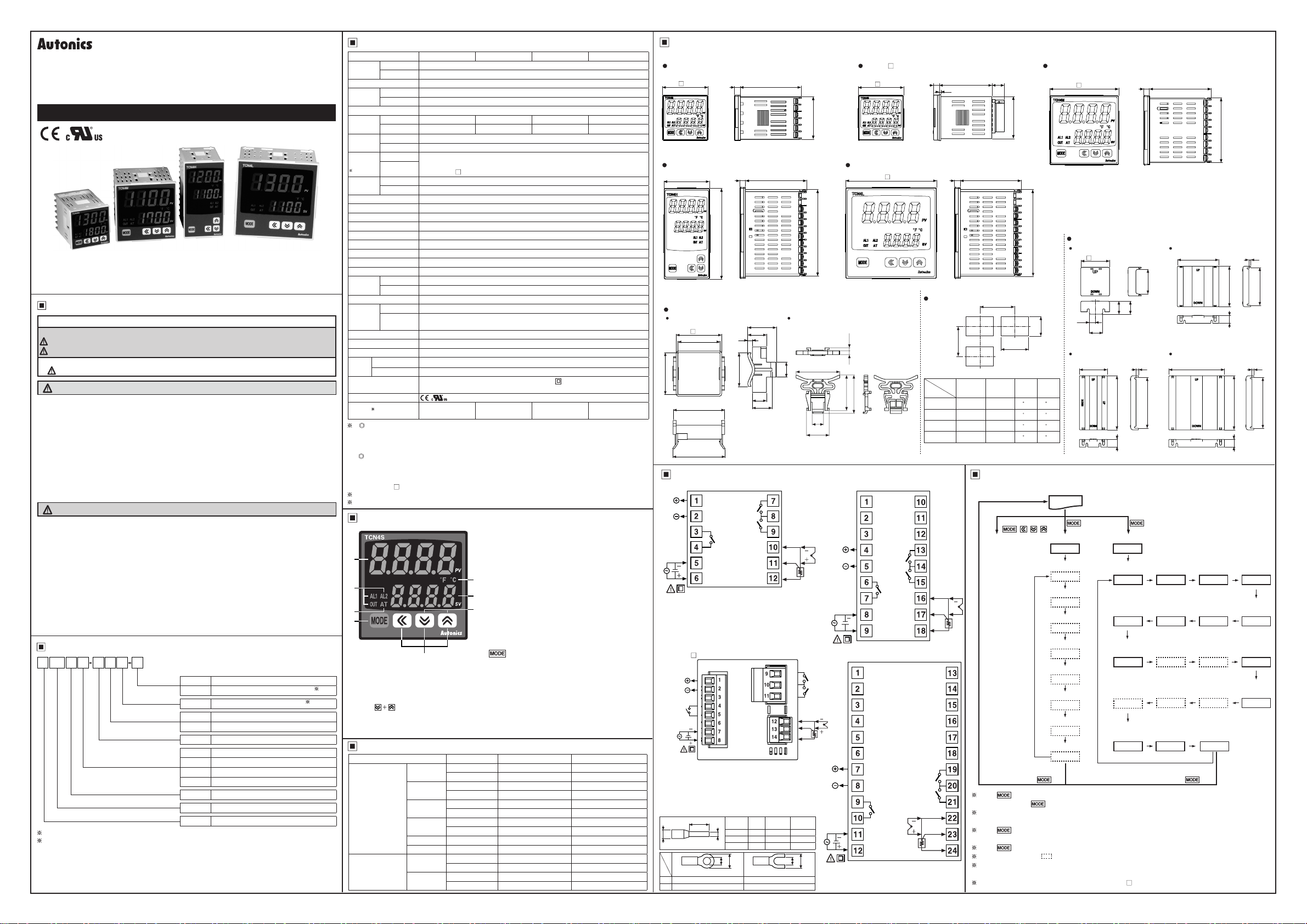
DRW1707 76AA
DUAL INDICATOR TEMPERATURE CONTROLLER
TCN4 SERIES
I N S T R U C T I O N M A N U A L
Please read the following safety considerations before use.
Safety Considerations
Please observe all safety considerations for safe and proper product operation to avoid hazards.
※
Safety considerations are categorized as follows.
※
Warning
Caution
※
The symbols used on the product and instruction manual represent the following
symbol represents caution due to special circumstances in which hazards may occur.
Warning
1. Fail-safe device must be installed when using the unit with machinery that may cause
serious injury or substantial economic loss. (e.g. nuclear power control, medical equipment,
ships, vehicles, railways, aircraft, combustion apparatus, safety equipment, crime/disaster
prevention devices, etc.)
Failure to follow this instruction may result in re, personal injury, or economic loss.
2. Install on a device panel to use.
Failure to follow this instruction may result in electric shock or re.
3. Do not connect, repair, or inspect the unit while connected to a power source.
Failure to follow this instruction may result in electric shock or re.
4. Check 'Connections' before wiring.
Failure to follow this instruction may result in re.
5. Do not disassemble or modify the unit.
Failure to follow this instruction may result in electric shock or re.
Caution
1. When connecting the power input and relay output, use AWG 20(0.50mm2) cable or over and
tighten the terminal screw with a tightening torque of 0.74~0.90N.m.
When connecting the sensor input and communication cable without dedicated cable, use
AWG 28~16 cable and tighten the terminal screw with a tightening torque of 0.74~0.90N.m.
Failure to follow this instruction may result in re or malfunction due to contact failure.
2. Use the unit within the rated specications.
Failure to follow this instruction may result in re or product damage.
3. Use dry cloth to clean the unit, and do not use water or organic solvent.
Failure to follow this instruction may result in electric shock or re.
4. Do not use the unit in the place where ammable/explosive/corrosive gas, humidity, direct
sunlight, radiant heat, vibration, impact, or salinity may be present.
Failure to follow this instruction may result in re or explosion.
5. Keep metal chip, dust, and wire residue from owing into the unit.
Failure to follow this instruction may result in re or product damage.
Ordering Information
T 4 S 2 4 R P
CN
Setting type
Item
1:
Only for TCN4S model.
2:
In case of the AC voltage model, SSR drive output method (standard ON/OFF control, cycle
control, phase control) is available to select.
The above specications are subject to change and some models may be discontinued
※
without notice.
Be sure to follow cautions written in the instruction manual and the technical descriptions
※
(catalog, homepage).
Thank you for choosing our Autonics product.
Failure to follow these instructions may result in serious injury or death.
Failure to follow these instructions may result in personal injury or product damage.
No-mark
Wiring method
Control output
Power supply
Sub output
Size
Digit
Bolt wiring method
P
Connector plug connection method
R
Relay contact + SSR drive output
2
24VAC 50/60Hz, 24-48VDC
4
100-240VAC 50/60Hz
2
Alarm1 + Alarm2 output
S
DIN W48 × H48mm
M
DIN W72 × H72mm
H
DIN W48 × H96mm
L
DIN W96 × H96mm
4
9999 (4 digit)
CN
Dual display type, set by touch switch
T
Temperature controller
1
2
Specication
Series
AC Power 100-240VACᜠ 50/60Hz
Power
supply
AC/DC Power
Allowable voltage range 90 to 110% of rated voltage
AC Power Max. 5VA(100-240VAC 50/60Hz)
Power
consumption
AC/DC Power
Display method 7 segment (PV: red, SV: green), other display part(green, red) LED method
PV(W×H) 7.0×15.0mm 9.5×20.0mm 7.0×14.6mm 11.0×22.0mm
Character
size
SV(W×H) 5.0×9.5mm 7.5×15.0mm 6.0×12.0mm 7.0×14.0mm
RTD DIN Pt100Ω, Cu50Ω (Allowable line resistance max.5Ω per a wire)
Input
type
TC K(CA), J(IC), L(IC), T(CC), R(PR), S(PR)
Display
RTD
accuracy
1
TC
Relay 250VACᜠ 3A 1a
Control
output
SSR 12VDCᜡ±2V 20mA Max.
Alarm output AL1, AL2 Relay: 250VACᜠ 1A 1a
Control method ON/OFF control, P, PI, PD, PID control
Hysteresis 1 to 100℃/
Proportional band(P) 0.1 to 999.9ºC/
Integral time(I) 0 to 9999 sec.
Derivative time(D) 0 to 9999 sec.
Control period(T) 0.5 to 120.0 sec.
Manual reset 0.0 to 100.0%
Sampling period 100ms
AC power 2000VAC 50/60Hz 1min.(between input terminal and power terminal)
Dielectric
strength
AC/DC power
Vibration
Mechanical OUT: Over 5,000,000 times, AL1/2: Over 5,000,000 times
Relay life
cycle
Electrical
Insulation resistance Min. 100MΩ(at 500VDC megger)
Noise
Memory retention Approx. 10 years (when using non-volatile semiconductor memory type)
Ambient temp. -10 to 50ºC, Storage: -20 to 60ºC
Environ
-ment
Ambient humi. 35 to 85%RH, Storage: 35 to 85%RH
Insulation type
Approval
2
Weight
1: At room temperature(23ºC±5ºC)
- Below 200ºC of thermocouple R(PR), S(PR) is (PV ±0.5% or ±3ºC, select the higher one) ±1 digit
- Over 200ºC of thermocouple R(PR), S(PR) is (PV ±0.5% or ±2ºC, select the higher one) ±1 digit
- Termocouple L (IC), RTD Cu50Ω is (PV ±0.5% or ±2ºC, select the higher one) ±1 digit
Out of room temperature range
- Below 200ºC of thermocouple R(PR), S(PR) is (PV ±1.0% or ±6ºC, select the higher one) ±1 digit
- Over 200ºC of thermocouple R(PR), S(PR) is (PV ±0.5% or ±5ºC, select the higher one) ±1 digit
- Thermocouple L(IC), RTD Cu50Ω is (PV ±0.5% or ±3ºC, select the higher one) ±1 digit
For TCN4S- -P, add ±1℃ by accuracy standard.
2: The weight includes packaging. The weight in parentheses is for unit only.
Environment resistance is rated at no freezing or condensation.
Unit Description
1
3
4
5
6. Adjustment
Used when entering into set value change mode, digit moving and digit up/down.
7. Digital input key
Press keys for 3 sec. to operate the set function
(RUN/STOP, alarm output reset, auto tuning) in digital input key [
8. Temperature unit (ºC/℉) indicator
It shows current temperature unit.
TCN4S TCN4M TCN4H TCN4L
24VACᜠ 50/60Hz, 24-48VDC
ᜡ
Max. 5V(24VAC 50/60Hz), Max. 3W(24-48VDC)
At room temperature(23ºC ± 5ºC): (PV ± 0.5% or ±1ºC, select the higher one) ± 1 digit
Out of room temperature range: (PV± 0.5% or ±2ºC, select the higher one)± 1digit
For TCN4S- -P, add ±1℃ by accuracy standard.
0.1 to 50.0℃/
℉ (
℉)
℉
1000VAC 50/60Hz 1min.(between input terminal and power terminal)
0.75mm amplitude at frequency of 5 to 55Hz in each X, Y, Z direction for 2 hours
OUT: Over 200,000 times(250VAC 3A resistive load)
AL1/2: Over 300,000 times(250VAC 1A resistive load)
Square-wave noise by noise simulator(pulse width 1㎲) ±2KV R-phase and S-phase
Double insulation or reinforced insulation (mark: , dielectric strength between
the measuring input part and the power part : AC power 2kV, AC/DC power 1kV)
Approx. 147g
(approx. 100g)
6
Approx. 203g
(approx. 133g)
1. Present temperature (PV) display (Red)
1) RUN mode: Present temperature (PV) display
2) Parameter setting mode: Parameter display
2. Set temperature (SV) display (Green)
1) RUN mode: Set temperature (SV) display
2) Parameter setting mode
: Parameter setting value display
3. Control/Alarm output display indicator
8
1) OUT: It turns ON when the control output is ON.
2
7
2) AL1/AL2: It turns ON when the alarm output is ON.
4. Auto tuning indicator
AT indicator flashes by every 1 sec during operating
auto tuning.
5. key
Used when entering into parameter groups,
returning to RUN mode, moving parameter, and saving
setting values.
Approx. 194g
(approx. 124g)
During SSR drive output type in CYCLE/
PHASE control, this indicator turns ON when
MV is over 3.0%.
DI-T
].
Approx. 275g
(approx. 179g)
Input Sensor and Temperature Range
Input sensor Display Temperature range(ºC) Temperature range(℉)
KCaH
KCaL
JIcH
JIcL
LIcH
LIcL
TCcH
TCcL
RPR
SPR
DPtH
DPtL
CUsH
CUsL
Thermocouple
RTD
K(CA)
J(IC)
L(IC)
T(CC)
R(PR)
S(PR)
DPt100Ω
Cu50Ω
-50 to 1200 -58 to 2192
-50.0 to 999.9 -58.0 to 999.9
-30 to 800 -22 to 1472
-30.0 to 800.0 -22.0 to 999.9
-40 to 800 -40 to 1472
-40.0 to 800.0 -40 to 999.9
-50 to 400 -58 to 752
-50.0 to 400.0 -58.0 to 752.0
0 to 1700 32 to 3092
0 to 1700 32 to 3092
-100 to 400 -148 to 752
-100.0 to 400.0 -148.0 to 752.0
-50 to 200 -58 to 392
-50.0 to 200.0 -58.0 to 392.0
Dimensions
TCN4S Series
64.5648
45
TCN4H Series
48
96
Bracket
TCN4S Series TCN4M, TCN4H, TCN4L Series
48.6
45
44.9
55
56
64.56
91.5
31
20
5
36
15
21
46
16
12
23.9
TCN4L Series
3.34
37.5
Connections
AL1 OUT
250VAC
1A 1a
AL2 OUT
250VAC
1A 1a
SSR
OUT
SOURCE
3)TCN4M Series
SSR
1
※
OUT
+
SOURCE
4)TCN4H/L
TC
1
※
2
※
1)TCN4S Series
SSR
※
OUT
SOURCE
1
2
※
AL1 OUT
AL2 OUT
Relay OUT
250VAC
3A 1a
250VAC
1A 1a
250VAC
1A 1a
B'
B
A
RTD
2)TCN4S- -P
SSR
1
※
OUT
Relay OUT
250VAC
3A 1a
2
※
SOURCE
TCN4 Series has selectable control output; Relay output, and
※
SSR drive output. AC/DC voltage type does not have SSRP
function.
1: 12VDC±2V 20mA Max.
※
2: AC voltage type: 100-240VAC 5VA 50/60Hz
※
AC/DC voltage type: 24VAC 5VA 50/60Hz
Use crimp terminals or teminals of size specied below.
※
c
<Crimp terminal>
a Min. 3.0 Min. 3.0
b Max.5.8 Max.5.8
a
<Round>
24-48VDC 3W
Terminal
a b c
number
1 to 8 6 Max. 1.7 Max. 3.7
b
9 to 11 6 to 8 Max. 2.1 Max. 4.2
12 to 14 6 to 8 Max. 1.5 Max. 3.5
a
b
<Forked>
(unit: mm)
a
B'
B
A
RTD
b
TC
TCN4S- -P
40.5
2
※
48
AL1 OUT
250VAC
1A 1a
AL2 OUT
250VAC
1A 1a
Relay OUT
250VAC
3A 1a
Series
Relay OUT
250VAC
3A 1a
56
1.7
64.5696
Panel cut-out
B
Size
A B C D
Series
TCN4S Min. 65 Min. 65 45
TCN4M Min. 90 Min. 90 68
TCN4H Min. 65 Min. 115 45
TCN4L Min. 115 Min. 115 92
Parameter Groups
1. All Parameter
SV setting Parameter 1group Parameter 2group
B'
B
+
TC
A
RTD
AL1 OUT
250VAC
1A 1a
AL2 OUT
250VAC
1A 1a
RTDTC
B'
B
A
Press key over 3 sec in any parameter group, it saves the set value and returns to RUN mode.
(Exception: Press key once in SV setting group, it returns to RUN mode).
If no key entered for 30 sec., it returns to RUN mode automatically and the set value of parameter
is not be saved.
Press key again within 1 sec. after returning to RUN mode, it advances of the rst parameter
of previous parameter group.
Press key to move next parameter.
Parameter marked in might not be displayed depending on other parameter settings.
Set parameter as 'Parameter 2 group → Parameter 1 group → Setting group of set value' order
considering parameter relation of each setting group.
1: It is not displayed for AC/DC power model (TCN4 -22R).
11.56
44.8
91.5
A
C
0.6
0
0.7
0
0.6
0
0.8
0
Please any key among
, , ,
TCN4M Series
64.5
672
Terminal cover(sold separately
RSA-COVER(48×48mm)
48.4
18
22
91.5
13
RHA-COVER(48×96mm)
0.6
0
0.7
0
0.8
0
0.8
0
9.8
22.5
47.2
D
45
68
92
92
)
41.5
4
86
RMA-COVER(72×72mm)
RLA-COVER(96×96mm )
Run mode
2sec. 4sec.
PAR1
AL1 alarm termerature
AL1
AL2 alarm termerature
AL2
Auto tunung
AT
Proportional band
P
Integral time
I
Derivative time
D
Manual reset
REST
Hysteresis
PAR2
Input
sensor
IN-Tㅑㅑ MAvF
Control type
C-MD
Control output
type
OUT
LBA detection
band
LBaㅑㅑB
Digital input
key
DI-K
Temperature
unit
UNIT
Control output
operation
O-FT
SSR drive output
※
method
SSrM
LBA
monitoring time
LBaT
Control output MV in case
of input break error
ErMV
HYS
3sec. 3sec.
1
70
94
Input
correction
IN-Bㅑㅑ
SV high-
limit value
H-SV
Control
cycle
Alarm output
hysteresis
AHYS
Parameter
lock
LOC
67.5
68.5
13
91.5
13
T
(unit: mm)
3
64
3
86
Input
digital lter
SV low-limit
value
L-SV
AL1 alarm
operation mode
AL-1
AL2 alarm
operation mode
AL-2
Loading...