


LE4S
Table of contents
 Loading...
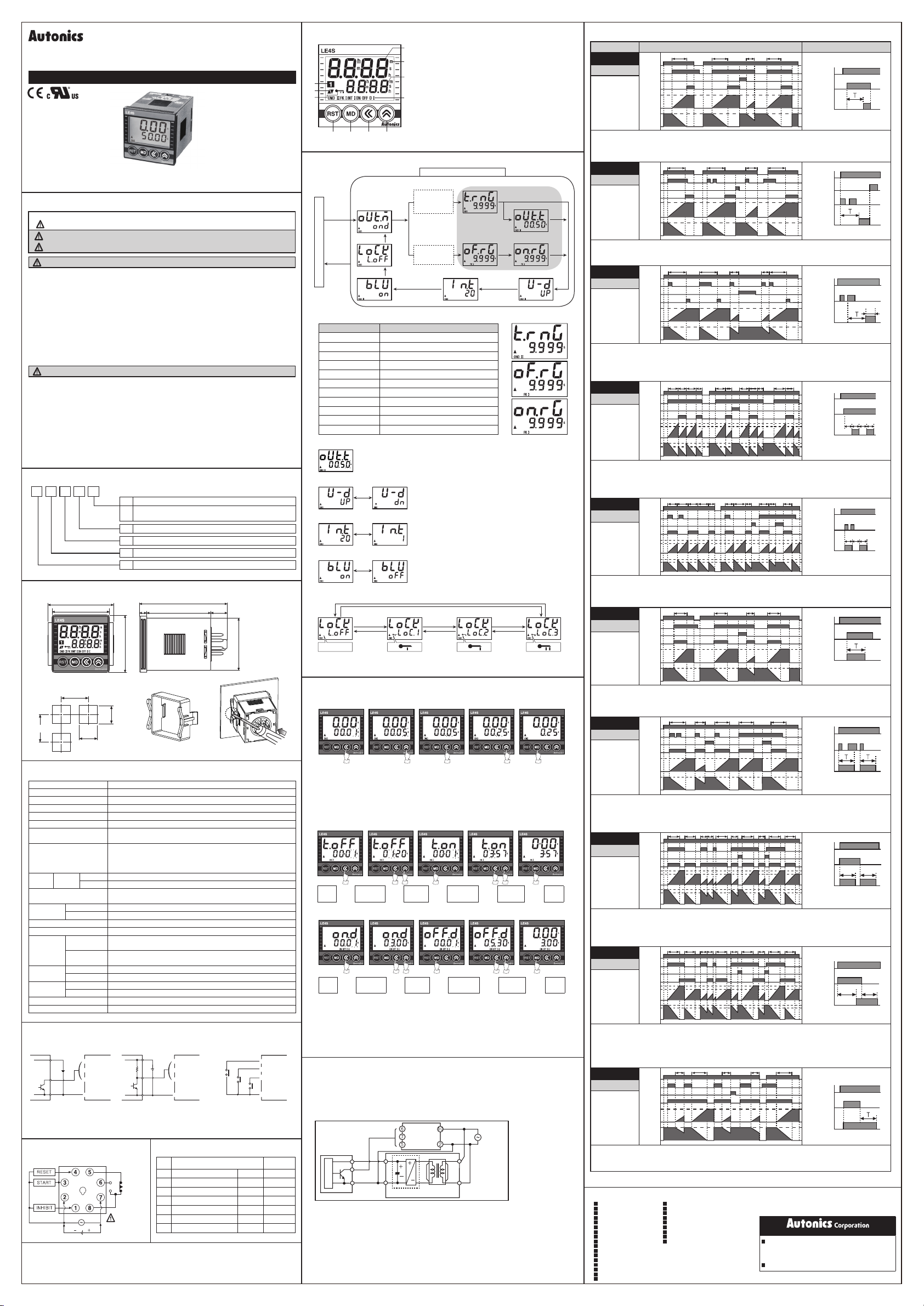
DRW171146AA
TIMER
LE4S
I N S T R U C T I O N M A N U A L
Please read the following safety considerations before use.
Safety Considerations
▣
※
Please observe all safety considerations for safe and proper product operation to avoid hazards.
※
1. Fail-safe device must be installed when using the unit with machinery that may cause
serious injury or substantial economic loss. (e.g. nuclear power control, medical
equipment, ships, vehicles, railways, aircraft, combustion apparatus, safety equipment,
crime/disaster prevention devices, etc.)
Failure to follow this instruction may result in re, personal injury, or economic loss.
2. Install on a device panel to use.
Failure to follow this instruction may result in electric shock or re.
3. Do not connect, repair, or inspect the unit while connected to a power source.
Failure to follow this instruction may result in electric shock or re.
4. Check ‘Connections’ before wiring.
Failure to follow this instruction may result in re.
5. Do not disassemble or modify the unit.
Failure to follow this instruction may result in electric shock or re.
1. When connecting the power/sensor input and relay output, use AWG 20(0.50mm2) cable or
over and tighten the terminal screw with a tightening torque of 0.74 to 0.90N.m.
Failure to follow this instruction may result in re or malfunction due to contact failure.
2. Use the unit within the rated specications.
Failure to follow this instruction may result in re or product damage.
3. Use dry cloth to clean the unit, and do not use water or organic solvent.
Failure to follow this instruction may result in electric shock or re.
4. Do not use the unit in the place where ammable/explosive/corrosive gas, humidity,
direct sunlight, radiant heat, vibration, impact, or salinity may be present.
Failure to follow this instruction may result in re or explosion.
5. Keep metal chip, dust, and wire residue from owing into the unit.
Failure to follow this instruction may result in re or product damage.
Ordering Information
▣
L E 4 S
Display
Dimensions
▣
●
Panel cut-out
Min.65
Specications
▣
Model LE4S
Power supply 24-240VACᜠ 50/60Hz, 24-240VDC
Display method LCD Display (backlight)
Allowable voltage range 90 to 110% of rated voltage
Power consumption 24-240VACᜠ: max. 4.5VA, 24-240VDCᜡ: max. 2W
Return time Max. 100ms
Min. input signal
(START,INHIBIT,RESET)
Input
(START,INHIBIT,RESET)
Control
output
Repeat·Setting·Voltage·
Temperature error
Environment
Insulation resistance Over 100MΩ (500VDC megger)
Dielectric strength 2,000VAC 50/60Hz for 1 minute
Vibration
Shock
Relay
life cycle
Approval
Unit weight Approx. 98g
※
Environment resistance is rated at no freezing or condensation.
Input Connections
▣
Solid-state input ◎Contact input
◎
Q1 Q2
·Q1 is ON: Operating
·Sensor: NPN open collector output
※
Be sure that it is not insulated between power input and input terminal block.
Connection
▣
※
The above specifications are subject to change and some models may be
discontinued without notice.
※
Be sure to follow cautions written in the instruction manual and the technical
descriptions (catalog, homepage).
Thank you for choosing our Autonics product.
symbol represents caution due to special circumstances in which hazards may occur.
Failure to follow these instructions may result in serious injury or death.
Warning
Failure to follow these instructions may result in personal injury or product damage.
Caution
Warning
Caution
Output
Size
Digit
Item
55
48
Min.65
+0.6
45
0
Type Time limit SPDT(1c)
Contact
Capacity 250VACᜠ 5A resistive load
Ambient temp. -10 to 55℃, storage: -25 to 65
Ambient humi. 35 to 85%RH
Mechanical
Malfunction
Mechanical 300m/s² (30G) X, Y, Z directions for 3 times
Malfunction 100m/s² (10G) X, Y, Z directions for 3 times
Mechanical Min. 10,000,000 times
Electrical Min. 100,000 times (250VAC 5A resistive load)
+
-
SOURCE
LE4S LE4S LE4SSensor Sensor
START
③
RESET
④
INHIBIT
①
0V
②
12-24VDC 12-24VDC
Time limit contact 1c
Time limit contact 2c,
A
Instantaneous contact 1c + Time limit contact 1c(Selectable)
S
DIN W48mm×H48mm
4
9999(4 Digit type)
E
Timer
L
LCD Display
※
8 Pin socket(PG-08, PS-08): Sold separately
76
566 14
48
●
Product mounting
+0.6
0
45
※
Insert product into a panel, fasten braket by pushing with
tools as shown above.
1ms, 20ms (selectable)
<No-voltage input>
Impedance at short-circuit: max. 1㏀,
Residual voltage: max. 0.5VDC,
Impedance at open-circuit: min. 100
Max. ±0.005% ±0.03sec (Signal Start)
Max. ±0.01% ±0.05sec (Power ON Start)
0.75mm amplitude at frequency of 10 to 55Hz in each X, Y, Z
direction for 1hour
0.5mm amplitude at frequency of 10 to 55Hz in each X, Y, Z direction
for 10 minutes
ᜢ ᜧ
·Q2 is ON: Operating
·Sensor: NPN output
CONTACT OUT
250VAC 5A
RESISTIVE LOAD
(Time limit
contact 1c)
▣
℃
START
③
RESET
④
INHIBIT
①
0V
②
Factory Default
Parameter Default
NO.
Output operation mode
1
Time Range
2
Time Up/Down
3
4 Min. input signal
Backlight
5
Key Lock
6
Setting time
7
44.8
ᜡ
㏀
S1
S2
S3
·S1, S2, S3 are ON
: Operating
·Please use reliable contact
enough to flow 5VDC 1mA.
OUT.M OND
T.RNG 99.99
U-D UP
IN.T 20
BLU ON
LOCK L.OFF
- 50.00
(unit: mm)
START
③
RESET
④
INHIBIT
①
0V
②
s
s
Front Panel Identication
▣
⑤
⑥
⑦
⑧ ⑨ ⑩ ⑪
Function Setting Mode Descriptions
▣
Output operation mode
key
*
3 sec
6)Key lock
RUN mode
key
*
3 sec
5)
Backlight
Time progressing display:It displays the current time.
①
①
Time setting display:It displays the setting time.
②
③
Time unit:It displays the time unit.
③
Operation mode:It displays the current operation mode
④
②
Output display:It displays the status of output contact.
⑤
UP/D OWN :It displays time progressing UP(▲), DOWN(▼).
⑥
Key lock display:It displays the status of key lock.
⑦
④
key :Used for initializing time progressing and output return
⑧
,
*key:Used for advancing to function setting mode, setting time
⑨
change checking.
<key:Used for advancing to setting time change mode and moving to
⑩
each digit.
>key
:Used for changing the set value.
⑪
Function setting mode
1)Time Range
OND
OND.1
[
]
, [
]
,
OND.2
INT
[
], [
]
,
INT.1
OFD
[
], [
]
mode
key
*
key
*
FLK
[
], [
NFD], [ NFD.1]
[
mode
key
*
key
*
FLK.1],
4)
T.OFF
Min. input signal
※
Time Range
*
*
OND.2
mode
*
key
key
key
.
2)One-Shot output time
*
Time Range
T.ON
*
3)Time Up/Down
.
key
key
1) Time Range
Parameter Time range specication
S
(9.999s) 0.010 sec to 9.999 sec
9.999
S
(99.99s) 0.01 sec to 99.99 sec
99.99
S
(999.9s) 0.1 sec to 999.9 sec
999.9
S
(9999s) 1 sec to 9999 sec
9999
S
(99m59s) 0 min 01 sec to 99 min 59 sec
99m 59
m
(999.9m) 0.1 min to 999.9 min
999.9
m
(9999m) 1 min to 9999 min
9999
m
(99h59m) 0 hour 01 min to 99 hour 59 min
99h 59
(99.99h) 0.01 hour to 99.99 hour
h
99.99
(999.9h) 0.1 hour to 999.9 hour
h
999.9
(9999h) 1 hour to 9999 hour
h
9999
2) One-Shot output time setting
It will be activated when selecting ON Delay 2[
(One-Shot-output mode).
(Time setting: 0.01 sec to 99.99 sec)
3) Time progress UP/DOWN setting
>
key
<
key
4) The minimum input signal setting
>
key
<
key
5)
Backlight setting
>
key
<
key
6) Key Lock selection
>
key
<
key
Turns off the
Lock mode.
Time Setting
▣
●
Output operation mode : OND, OND I, OND II, INT, INT I, OFF D
UP[ UP]: Time progressed from 0 to setting time.
DOWN[ DN]: Time progressed from setting time to 0.
Set the minimum input signal of RESET, START and INHIBIT
Min. input signal: Choose 1ms and 20ms
Set Backlight (ON[ ON], OFF[
>
key
<
key
>
key
<
key
key cannot
,
be used.
<,>key cannot
be used.
[Fig. 1] [Fig. 2] [Fig. 3] [Fig. 4] [Fig. 5]
Press
key in RUN mode, time set digits will flash.[
①
<
Change setting time by press < or >keys.[
②
-<key:Shift the setting digits.
->key:
Shift the flashing position value. As press >key once, it will increase by 1digit, number will
increase faster by press >key for over 2sec.
When the setting is completed, it will be saved and return to RUN mode by pressing *key.[
③
●
Output operation mode : FK, FK
RUN
mode
●
Output operation mode : ON OFF D, ON OFF D
RUN
mode
※
It is able to change the setting time during the time progressing, but be sure about the time
progressing while changing of the time.
※
If pressing *key while setting time is shorter than min. setting time, setting value will be flickering
three times and it will be returned to setting mode again, not to RUN mode.
※
If there is no additional key operations after entering into setting mode, it will be return to RUN mode.
(Setting value is not saved.)
※
Min. Setting time: 0.01 sec.
(In case of OND,OND I and ONDⅡ modes, it is able to set 0 since no min. setting time is applied.)
Cautions during Use
▣
1. Follow instructions in 'Cautions during Use'. Otherwise, It may cause unexpected accidents.
2. When supplying or turning off the power, use a switch or etc. to avoid chattering.
3. Install a power switch or circuit breaker in the easily accessible place for supplying or disconnecting
the power.
4. In order to block peripheral current, use isolation transformer which of secondary part is not
grounded as (Figure 1) to supply power to the external input device.
(Figure 1)
< Sensor >
5. Do not connect two or more timers with only one input contact or transistor simultaneously.
6. Keep away from high voltage lines or power lines to prevent inductive noise.
In case installing power line and input signal line closely, use line lter or varistor at power line and
shielded wire at input signal line.
Do not use near the equipment which generates strong magnetic force or high frequency noise.
7. This unit may be used in the following environments.
Indoors (in the environment condition rated in 'Specications')
①
Altitude max. 2,000m
②
Pollution degree 2
③
Installation category II
④
Setting of
<
→
T.off Time
Setting of
<
→
ON.D
Time
Main circuit
<>
→
the time
<>
→
Rectication
circuit
I
Setting
Setting
the time
START
RESET
INHIBIT
Fig.
*
→
*
→
Isolation
transformer
Fig.
2,3,4]
Setting of
T.on Time
I
Setting of
OFF.D
Time
<External sensor
power supply>
OND.2
OFF
1]
<>
→
<>
→
Power
] output operation mode
]).
>
key
<
key
,<,>key
,
cannot be used.
Fig.
Setting
the time
Setting
the time
RUN
*
→
mode
RUN
*
→
mode
5]
Output Operation Mode
▣
Mode
[
]
OND
OND
ON Delay
1. Timing operation starts when START signal is ON at status of power on.
2.
Output will be ON when timing operation is progressed up to the setting time. Display value will be HOLD.(① position)
3. When RESET signal is ON, display value and output will be reset.(② position)
4. If RESET signal is OFF while START signal is ON,“STEP 1”will be restarted.(③ position)
5. When START signal is OFF, display value and output will be reset.(④ position)
[
]
OND.1
OND
I
ON Delay 1
1. Timing operation starts when START signal is ON at status of power on.
2.
Output will be ON when timing operation is progressed up to the setting time. Display value will be HOLD.(① position)
3. Even though START signal is applied repeatedly, only the initial signal is recognized.(② position)
4. When RESET signal is ON, display value and output will be reset.(③ position)
[
]
OND.2
OND
II
ON Delay 2
(One-Shot Output)
1. Timing operation starts when START signal is ON at status of power on.
2. Time limit output will be ON and goes OFF during Tout setting time when timing operation is progressed up
to the setting time. Display value will be HOLD.(① position)
3. When RESET signal is ON, display value and output will be reset.
4.
If START signal is applied while time is progressing, Timing operation will be reset and started again.(② position)
5. Tout setting range: 0.01 sec~99.99 sec.
[
]
FLK
FK
Flicker
(Toff operation
precedes
Ton operation)
1. If START signal is ON, output will be repeatedly OFF during Toff setting time and will be OFF during Ton
setting time when power is ON.
2. When RESET signal is ON, display value and output will be reset.
3. If RESET signal is OFF when START signal is ON, “STEP 1” will be restarted.
4. When START signal is OFF, display value and output will be reset.
5. It is able to set each Toff time and Ton time separately. In [
[
]
FLK.1
FK
I
Flicker 1
(Ton operation
precedes
Toff operation
)
1. If START signal is ON, output will be repeatedly ON during Ton setting time and will be OFF during Toff
setting time when power is ON.
2. Even though START signal is applied repeatedly, only the initial signal is recognized.(① position)
3. When START signal is ON, display value and output will be reset. If START signal is ON, it will be restarted.
4. It is able to set each Toff time and Ton time separately. In [
[
]
INT
INT
Interval
1. Output will be ON when START signal is ON at status of power on and Timing operation starts.
2. Output will be OFF when timing operation is progressed up to the setting time. Display value will be HOLD.
3. When RESET signal is ON, display value and output will be reset.(① position)
4. If RESET signal is OFF when START signal is ON,“STEP 1”will be restarted.
5. When STRAT signal is OFF, display value and output will be reset.(② position)
[
]
INT.1
INT
I
Interval 1
1. Output will be ON when START signal is ON at status of power on and Timing operation starts.
2. Output will be OFF when timing operation is progressed up to the setting time. Display value will be HOLD.
3. Even though START signal is applied repeatedly, only the initial signal is recognized.(① position)
4. If START signal is ON after timing operation is progressed up to the setting time, Output will be ON and
setting time will be reset and then timing setting starts.
5. When RESET signal is ON, display value and output will be reset.(② position)
[
]
NFD
ON OFF D
ON OFF Delay
1.
If START signal is ON when power is on, Output will be ON when timing operation is progressed up to the Ton setting time(OnDelay). IF START signal is OFF, output will be ON when timing operation is progressed up to the Toff setting time (OFF-Delay).
2. If START signal is applied repeatedly, output is ON and display value will be reset.(① position)
3. When RESET signal is ON, display value and output will be reset. When RESET signal is OFF while
START signal is ON, it will be operating as On-Delay.(② position)
4. It is able to set each Toff time and Ton time separately.
[
]
NFD.1
ON OFF D
I
ON OFF Delay
1
1.
If START signal is ON when power is on, timing operation starts. Output will be ON when timing operation is progressed up to the Ton setting
time(On-Delay). IF START signal is OFF, output will be ON when timing operation is progressed up to the Toff setting time (OFF-Delay).
2.
Output will be ON when START signal is ON and goes OFF during setting time and display value will be reset.(① position)
3.
Output will be OFF when START signal is OFF and goes ON during setting time and display value will be reset.(
4. When RESET signal is ON, display value and output will be reset. When RESET signal is OFF while
START signal is ON, it will be operating as On-Delay.(② position)
5. It is able to set each Toff time and Ton time separately.
[
]
OFD
OFF D
OFF Delay
1. If START signal is ON when power is on, output will be ON.
2. When START signal is OFF, timing operation starts. Output will be OFF when timing operation is
progressed up to the setting time. Display value will be HOLD.
3. When RESET signal is ON, display value and output will be reset.
Reset: Up mode -> Display value is“0”, Output is“OFF”.
※
DOWN mode -> Display value is“setting time”, Output is“OFF”.
Major Products
▣
Photoelectric Sensors Temperature Controllers
Fiber Optic Sensors Temperature/Humidity Transducers
Door Sensors SSRs/Power Controllers
Door Side Sensors Counters
Area Sensors Timers
Proximity Sensors Panel Meters
Pressure Sensors Tachometer/Pulse (Rate)Meters
Rotary Encoders Display Units
Connector/Sockets Sensor Controllers
Switching Mode Power Supplies
Control Switches/Lamps/Buzzers
I/O Terminal Blocks & Cables
Stepper Motors/Drivers/Motion Controllers
Graphic/Logic Panels
Field Network Devices
Laser Marking System (Fiber, Co₂, Nd: YAG)
Laser Welding/Cutting System
Time chart( T:Setting time,
T T
POWER
START
RESET
RELAY OUT
Setting time
UP
Setting time
DOWN
POWER
RELAY OUT
Setting time
UP
Setting time
DOWN
POWER
RELAY OUT
Setting time
UP
Setting time
DOWN
POWER
RELAY OUT
UP
DOWN
POWER
RELAY OUT
UP
DOWN
POWER
RELAY OUT
Setting time
UP
Setting time
DOWN
POWER
RELAY OUT
Setting time
UP
Setting time
DOWN
POWER
RELAY OUT
UP Ton
DOWN
POWER
RELAY OUT
UP
DOWN
POWER
RELAY OUT
Setting time
UP
Setting time
DOWN
1
0
0
START
RESET
1
0
0
START
RESET
0
0
Tof f Toff Tof f Tof fTon Tof f Ta Ta To n TonTa
START
RESET
ⓐ
ⓑ
0
ⓐ
ⓑ
0
Ton To n Ton TonTof f To n To ff Ta Toff TaTa
START
1
RESET
ⓐ
ⓑ
0
ⓐ
ⓑ
0
T T TTa
START
RESET
0
0
START
1
RESET
0
0
START
RESET
Tof f
0
Tof f
Ton
0
START
RESET
ⓐ
ⓑ
0
ⓐ
ⓑ
0
Ta T
START
RESET
0
0
T > Ta ) Operation
Ta
T
342
T Ta TT
3
2
T Ta Ta TT
] mode, timing operation starts with Toff.
FLK
] mode, timing operation starts with Ton.
FLK.1
2
1
TT T TTa
2
Ta Ta To n TonTon To ff Ta Toff Ta To ff
1 2
Ta Ta To n TonTo n Tof f Ta Tof f Ta Toff
1 2
Ta Ta
HEADQUARTERS:
18, Bansong-ro 513beon-gil, Haeundae-gu, Busan,
South Korea, 48002
TEL: 82-51-519-3232
E-mail: sales@autonics.com
T
POWER
START
RELAY
OU
T
POWER
RESET
START
RELAY
OU
T
POWER
START
RELAY
OU
T
ⓐTout:
POWER
START
RELAY
OU
T
ⓐToff:OFF Setting time
ⓑTon:ON Setting time
POWER
START
RELAY
OU
T
ⓐToff:OFF Setting time
ⓑTon:ON Setting time
POWER
START
RELAY
OU
T
POWER
START
RELAY
OU
T
POWER
START
RELAY
OU
T
ⓐTon:ON Setting
ⓑToff:OFF
POWER
START
RELAY
OU
T
ⓐTon:ON Setting
ⓑToff:OFF
POWER
START
RELAY
OU
T
http://www.autonics.com
Output time
ⓐⓑⓐⓑ
ⓑⓐⓑ
ⓐ ⓑ
Setting time
ⓐ ⓑ
Setting time
position)
①
DRW171146AA
ⓐ
time
time
Loading...