

Autonics KT-502H SERIES Instruction Manual
DRW190788AA
Autonics
Temperature Transmitters
with HART protocol
KT-502H SERIES
I N S T R U C T I O N M A N U A L
Please read the following safety considerations before use.
Safety Considerations
Please observe all safety considerations for safe and proper product operation to avoid
※
hazards.
symbol represents caution due to special circumstances in which hazards may occur.
※
Warning
Caution
Warning
1.Fail-safe device must be installed when using the unit with machinery that may cause seri-
ous injury or substantial economic loss. (e.g. nuclear power control, medical equipment,
ships, vehicles, railways, aircraft, combustion apparatus, safety equipment, crime/disaster
prevention devices, etc.)
Failure to follow this instruction may result in personal injury, economic loss or re.
2.Do not use the unit in the place where ammable/explosive gas, high humidity, direct sun-
light, radiant heat, vibration, impact, or salinity may be present.
Failure to follow this instruction may result in explosion or re.
3.Do not connect, repair, or inspect the unit while connected to a power source.
Failure to follow this instruction may result in electric shock or malfunction.
4.For installing the unit, ground it exclusively and use over AWG 11(4mm²) ground cable.
Failure to follow this instruction may result in electric shock.
5.Do not disassemble or modify the unit.
Failure to follow this instruction may result in re or electric shock.
6.Check 'Connections' before wiring.
Failure to follow this instruction may result in re.
Caution
A
1.Use the unit within the rated specications.
Failure to follow this instruction may result in re or product damage.
2.Use a dry cloth to clean the unit, and do not use water or organic solvent.
Failure to follow this instruction may result in re or electric shock.
3.Keep the product away from metal chip, dust, and wire residue which ow into the unit.
Failure to follow this instruction may result in re or product damage.
Ordering Information
~
Item Description
①Mounting bracket
②Input range
Input Type and Range
~
Input type Input range ( ) Input range ( )
RTD
Resistance
transmitter
Thermocouple
Analog Voltage
※
The above specications are subject to change and some models may be discontinued
without notice.
※
Be sure to follow cautions written in the instruction manual and the technical descriptions
(catalog, homepage).
Thank you for choosing our Autonics product.
Failure to follow these instructions may result in serious injury or death.
Failure to follow these instructions may result in personal injury or product damage.
KT
c=J-c=J
0 Without bracket 1 With bracket
1: To order this unit, write the temperature sensor type
and the input range.
502H
·c
DPt100Ω
DPt500Ω
DPt1000Ω
Cu50Ω
Cu100Ω
Ni100Ω
Ni500Ω
Ni1000Ω
Resistance (Ω)
B (PtRh30-PtRh6) 0 to 1820 32 to 3308
E (NiCr-CuNi)
J (Fe-CuNi)
K (NiCr-Ni)
N (NiCrSi-NiSi)
R (PtRh13-Pt)
S (PtRh10-Pt)
T (Cu-CuNi)
200 to 850
200 to 250
200 to 250
50 to 150
50 to 150
60 to 180
60 to 180
60 to 150
0 to 400Ω
0 to 2000Ω
270 to 1000
210 to 1200
270 to 1372
270 to 1300
50 to 1768
50 to 1768
270 to 400
10-
75mV
100-100mV
100-500mV
100-2000mV
(-270 to 1372, K)
0
□
① ②
328 to 1562
328 to 482
328 to 482
58 to 302
58 to 302
76 to 356
76 to 356
76 to 302
-
454 to 1832
346 to 2192
454 to 2501.6
454 to 2372
58 to 3214.4
58 to 3214.4
454 to 752
-
"F
Specications
Series KT-502H
Power supply 10.5-45VDC (with backlight LCD)
Display method
Display range -19999 to 99999
Set ing method HART-protocol (no setting key)
Response time 1 sec
RTD
Thermocouple K, J, T, E, N, S, B, R
Resistance trans. (Ω) 0 - 400Ω, 0 - 2000Ω
Input type
Voltage trans. (mV)
Output DC4-20mA (2-wire)
Accuracy ±0.3%
Alarm Below 3.8mA, Over 20.5mA / Sensor break 3.6mA
Load max. (V power supply - 7.5V)/0.22A
Galvanic insulation 2kVAC (input/output)
Ambient temp. -20 to 70 ℃, storage: 20 to 80 ℃
Environ-
I
ment
Ambient humi. 0 to 85%RH, storage: 0 to 85%RH
I
Explosion class
Protection structure IP67
Material Body: Aluminum (AlDc.8S), Cover O-Ring: Buna N
Weight
※1: The explosion class specication is acquired and managed by KONICS.
※2: The weight includes packaging. The weight in parenthesis is for unit only.
※Environment resistance is rated at no freezing or condensation.
※1
※2
PV display part : 7-segment 5-digit
Parameter display part : 14-segment 8-digit
52-bar meter
DPt100Ω, DPt500Ω, DPt1000Ω
Ni100Ω, Ni500Ω, Ni1000Ω
Cu50Ω, Cu100Ω
-
10 - 75mV
-
100 - 100mV
-
100 - 500mV
-
100 - 2000mV
Ex d IIC T6
Approx. 1.4 kg (approx. 1.2 kg)
(character size: W4×H8mm),
(character size: W2.6×H4.8mm),
Error Display and Troubleshooting
Display Error Troubleshooting
ERR05
ERR06
ERR07
ERR08
~
Connect a HART communicator and set temperature range as below by a HART
communicator.
~
I
I
Temperature sensor A, B or all sensors
are disconnected.
Temperature sensor B is disconnected.
When PV is lower than the low-limit
value of set temperature range.
When PV is higher than the high-limit
value of set temperature range.
Temperature Range Setting
Online (Generic)
1. Device Setup
2. PV
3. PV Ao
4. PV LRV
5. URV SAVE
1. PV LRV
2. URV
HELP HOME
PV LRV
0.000 deg C
0.000
HELP DEL ESC ENTER
1. PV LRV
2. URV
HELP HOME
PV URV
100.000 deg C
100.000
HELP DEL ESC ENTER
1. PV LRV 0.000 deg C
2. URV 100.000 deg C
HELP SEND HOME
- WARNING -
Pressing ' OK ' will
change device output
put 100P in manual
- WARNING -
Return control 100P
To automatic control
1. PV LRV 0.000 deg C
2. URV 100.000 deg C
HELP HOME
O K
①
②
③
④
⑤
⑥
When the set temperature range is correct,
⑦
⑧
⑨
Check the temperature
sensor.
Check low-limit value of the
set temperature range.
Check high-limit value of the
set temperature range.
Press the
Select the '4. PV LRV' by , keys
and press the
key for 3 sec.
~
key.
[:±]
l!l
III
Select '1. PV LRV' (Low temperature range)
and press the
Set
Low temperature range and press
the (F4) key.
IENTERI
[:±]
key.
Select '2. URV' (High temperature
range) and press the
Set
High temperature range and press
the
(F4) key.
IENTERI
press the
Press the
Press the
I
SEND
IOKI
IOKI
[:±]
(F2) key.
I
(F4) key.
(F4) key.
key.
Check the set temperature range.
Press the
HART communication is OFF.
IHOMEI
(F3) key.
Current Trim Adjustment
Connect a HART communicator and adjust current trim as below by a HART
communicator.
①
1. Device Setup
2. PV
3. PV Ao
4. PV LRV
5. URV
1. Process Variables
2. Diag/Service
3. Basic Setup
4. Detailed Setup
5. Review
1. Test device
2. Loop test
3. Calibration
4. D/A trim
WARN-Loop should be
removed from
automatic control
Connect reference
meter
Setting d dev
output to 4mA
Enter meter Value
4.000
Fid dev output 4.000
mA equal to reference
meter ?
1. Yes
2. No ABORT ENTER
Setting d dev.
output to 20mA
Enter meter Value
20.000
Fid dev output 20.000
mA equal to reference
meter ?
1. Yes
2. No ABORT ENTER
NOTE-Loop may be
returned to automatic
control
Diag/Service
1. Test device
2. Loop test
3. Calibration
4. D/A trim
Device Disconnected
1. Oine
2. Online
3. Frequency Device
4. Utility
ABORT O K
ABORT O K
ABORT O K
HELP DEL ABORT ENTER
ABORT O K
HELP DEL ABORT ENTER
ABORT O K
HELP SAVE HOME
RETRY QUIT
Select the '1. Device Setup' by
,
keys and press the key.
②
Select the '2. Diag/Service' by
,
keys and press the key.
l!l
III
③
Select the '4. D/A trim' by
and press the
④
Press the
⑤
Press the
⑥
Press the
⑦
Press the
~
IOKI
IOKI
IOKI
IENTERI
(F4) key.
(F4) key.
(F4) key.
~
,
l!l
key.
(F4) key to set 4 mA
III
display value.
⑧
If output display value is correct, select
'1. Yes' and press the
IENTERI
key. If not, select '2. No' and press
the (F4) key and re-set the
IENTERI
display value.
E.g.) If output display value is 3.89mA,
select 3.89 and press the
(F4) key.
⑨
Press the
⑩
Press the
display value.
⑪
If output display value is correct, select
(F4) key.
IOKI
(F4) key to set 20mA
!ENTER!
'1. Yes' and press the
key. If not, select '2. No' and press
the (F4) key and re-set the
IENTERI
display value.
⑫
Press the
⑬
Press the
⑭
Press the
⑮
Press the
(F4) key.
IOKI
(F3) key.
IHOMEI
(F3) key.
I QUIT I
(F3) key to complete
Q1']
IENTERI
!ENTERI
the adjustment.
keys
(F4)
(F4)
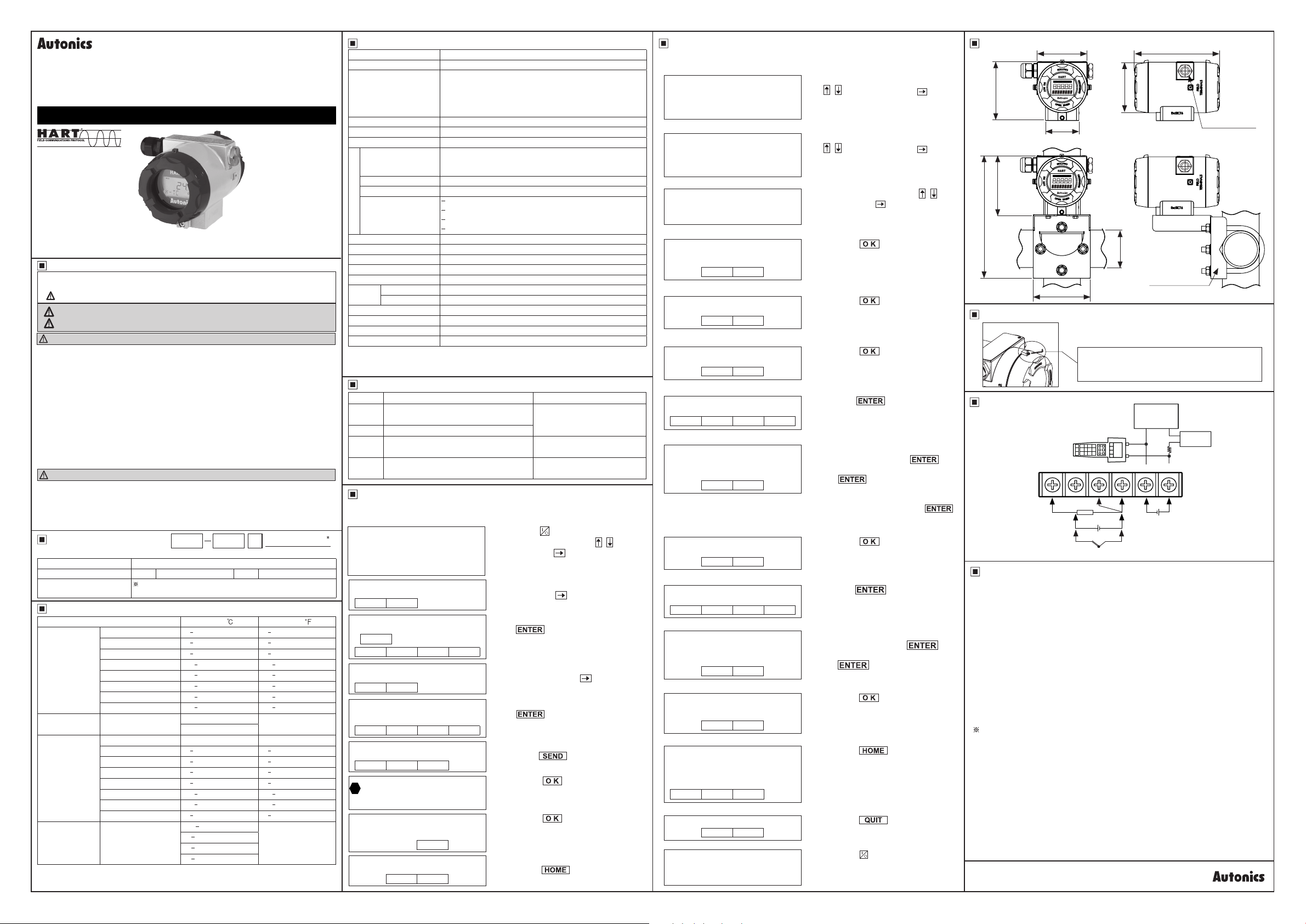
Dimensions
96
83
Ø83
55
142
(unit: mm)
2- (1/2 14NPT)
● Mounting bracket
96
200
DN50
(2B Pipe)
Mounting bracket
94
Opening Cover
To open the cover, unscrew the M3 × 6L headless
bolt using a 1.5 hexagon wrench and rotate the
cover.
Connections
HART
Communicator
1 2 3 4 5 6
11~11~~11
A B b
RTD
mV
+ -
TC
8
+ -
Cautions During Use
~
1. Follow instructions in 'Cautions during Use'.
O herwise, it may cause unexpected accidents.
2. Power supply should be insulated and limited voltage/current or Class 2, SELV power
supply device.
3. Keep away from high voltage lines or power lines to prevent inductive noise.
Do not use near he equipment which generates strong magnetic force or high frequency
noise.
4. Install a power switch or circuit breaker in the easily accessible place for supplying or disconnecting the power.
5. The explosion-proof standard of his unit is Ex d IIC T6, protection structure of this unit is
IP67 and the range of max. surface temperature is below 85℃.
Use the veried explosion-proof electric connection (cable gland or sealing t ing)
6. This unit may be used in the following environments.
①Indoors (in the environment condition rated in 'Specications')
②Altitude max. 2,000m
③Pollution degree 2
④installation Category II
The explosion-proof unit is certied and the same specications which is reported to
*
Korea Gas Safety Corporation. (This unit is manufactured following by the announcement 2013-54 of Ministry of Employment and Labor of Korea.)
Indicator
Recorder
DCS
Controller
-
+
Power supply
10.5-45VDC
Power
Supply
Min. 250Ω
Autonics
 Loading...