

Page 1
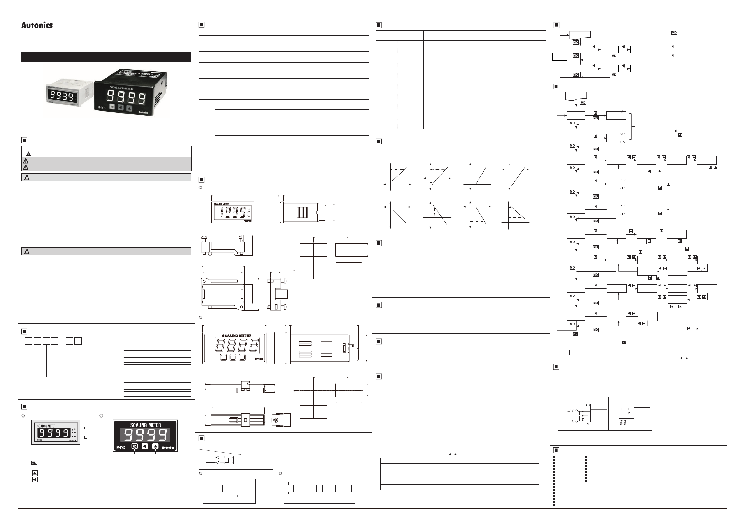
DRW160942AC
SCALING METER
M4NS/M4YS SERIES
I N S T R U C T I O N M A N U A L
Thank you for choosing our Autonics product.
Please read the following safety considerations before use.
Safety Considerations
※
Please observe all safety considerations for safe and proper product operation to avoid hazards.
※
symbol represents caution due to special circumstances in which hazards may occur.
Warning
Caution
Warning
1. Fail-safe device must be installed when using the unit with machinery that may cause
serious injury or substantial economic loss. (e.g. nuclear power control, medical
equipment, ships, vehicles, railways, aircraft, combustion apparatus, safety equipment,
crime/disaster prevention devices, etc.)
Failure to follow this instruction may result in fire, personal injury, or economic loss.
2. Install on a device panel to use.
Failure to follow this instruction may result in fire.
3. Do not connect, repair, or inspect the unit while connected to a power source.
Failure to follow this instruction may result in fire.
4. Check 'Connections' before wiring.
Failure to follow this instruction may result in fire.
5. Do not disassemble or modify the unit.
Failure to follow this instruction may result in fire.
Caution
1. When connecting the power/measurement input, use AWG 24(0.20mm2) to AWG 15
(1.65mm
1.18N.m.
Failure to follow this instruction may result in fire or malfunction due to contact failure.
2. Use the unit within the rated specifications.
Failure to follow this instruction may result in fire or product damage.
3. Use dry cloth to clean the unit, and do not use water or organic solvent.
Failure to follow this instruction may result in fire.
4. Do not use the unit in the place where flammable/explosive/corrosive gas, humidity,
direct sunlight, radiant heat, vibration, impact, or salinity may be present.
Failure to follow this instruction may result in fire or explosion.
5. Keep metal chip, dust, and wire residue from flowing into the unit.
Failure to follow this instruction may result in fire or product damage.
Ordering Information
M 4 N S N A
Item
Unit Description
M4NS-NA
1
1. Display value, parameter, error display
2. M, key:
3. ▲, key: When enter into the status of parameter setting
4. ◄,
※
The above specications are subject to change and some models may be
discontinued without notice.
※
Be sure to follow cautions written in the instruction manual and the technical
descriptions (catalog, homepage).
Failure to follow these instructions may result in serious injury or dea h.
Failure to follow these instructions may result in personal injury or product damage.
2
) cable and tighten the terminal screw with a tightening torque of 0.98 to
Measuring input range
Power supply
Measurment function
Size
Digit
A DC4-20mA
N Loop powered type
S Scaling
N DIN W48×H24mm
Y DIN W72×H36mm
4 9999 (4-digit)
M Meter
M4YS-NA
2
3
1
4
2 4 3
When enter into Parameter group, return to RUN mode,
after completing Parameter setting
key: When enter into the status of parameter setting and move digit
Specications
Model M4NS-NA M4YS-NA
Power supply Loop powered type
Display method 7-segment LED display (red)
Character height 10mm 14mm
Display accuracy
Display cycle 0 5 sec/1 sec/2 sec/3 sec/4 sec/5 sec
Resolution 12,000 resolution
Max. display -1999 to 9999
Setting type Setting type with the front keys
Measuring input range
Self-diagnosis function Error display function
Insulation resistance Over 100MΩ (at 500VDC megger)
Dielectric strength 2000VAC 50/60Hz for 1 min
Vibration
Shock
Environ
-ment
Unit weight Approx. 44g Approx. 110g
※
1: Ambient temperature (25℃ ±5℃): F.S. 0.3% rdg of ±1-digit (-10 to 50℃: F.S. 0.4% rdg ±1-digit)
※
2: Impedance between input lines: Max. 600Ω (based on 24VDC)
Please be aware that activating input power is based on 24VDC, and the recommended
impedence also will be lowered if the activating power is lower.
※
Environment resistance is rated at no freezing or condensation.
Dimensions
※
1
F.S. 0 3% rdg ±1-digit
※
2
DC4-20mA
Mechanical
Malfunction
Mechanical 300m/s² (approx. 30G) in each X, Y
Malfunction 100m/s² (approx. 10G) in each X, Y, Z direction for 3 times
Ambient temp. -10 to 50℃, storage: -25 to 60
Ambient humi. 35 to 85%RH, storage: 35 to 85%RH
0.75mm amplitude at frequency of 10 to 55Hz (for 1 min) in each X, Y
direction for 1 hour
0 5mm amplitude at frequency of 10 to 55Hz (for 1 min) in each X, Y, Z
direction for 10 min
, Z direction for 3 times
℃
(unit: mm)
M4NS-NA
48
● Bracket
2323
48.6
45.2 11 6
M4YS-NA
● Bracket
412
60
Connections
※
Use terminals of size specied below.
a b
a
Min.
b
<Forked>
3 5mm
M4NS-NA
INPUT
1 2 3 4 5
DC4-20mA
24
36 3
Max.
7.0mm
4
36
9
M4YS-NA
48
21
● Panel cut-out
Min. 60
Min. 37
7772 6
● Panel cut-out
Min. 91
Min. 40
14.5
INPUT
1 2 3 4 5 6 7
DC4-20mA
0.5
45
0
0.7
68
0
Parameter
Display Function Setting range
-1 999 to 9.999,
-19.99 to 99.99,
-199.9 to 999 9,
-1999 to 9999
0000, 000.0,
00.00, 0.000
-100 to 100
0 900 to 1.100
0 to 30
0 5, 1.0, 2.0, 3 0,
4 0, 5.0
, Z
Low scale Low limit display value for 4mA input
L-SC
High scale High limit display value for 20mA input
H-SC
Decimal point Set Decimal point position
DOT
Input bias low
INbL
Input bias high
INbH
Max /Min. time
PEkT
Display time Selectable sampling period (sec)
DIsT
Error % Set % of HHHH/LLLL display range 0, 1, 2, 3, 4
ePCT
Lock Set the lock function ON, OFF
LOC
Correct the Low-limit value of display
value (digit)
Correct the High-limit value of display
value (%)
See the Max./Min. value monitoring
delay time (sec)
Display Scale Function
This function is to display the value with setting certain Hi/Low limit value against DC4-20mA input.
For example If set a=DC 4mA, b=DC 20mA and A,B as display value, it will be displayed a=A, b=B.
Display
B
A
a
b
Display
a
b
A
B
Correction Function
0.3
0
This function is to adjust the error of display value after calculating scale value for measuring input and
22.2
also correct the input error of sensor etc.
: -100 to 100 [Adjust deviation of low value],
INbL
: 0.900 to 1.100 [Correct gradient (%) of high value]
INbH
E.g.) When display value is 0 0 to 500.0 against 4-20mA input, if the display value is "1.2" for 4mA
input, set -12 (ignore the decimal point) as
offset of Low display value.
※
When completed above Low value setting then apply 20mA, if the display value is "500.5", the
correction value will be 5005/5000=0.999, set 0 999 as
value is 5005×0.999 = 5000). It is also ignore the decimal point.
Display Cycle Delay Function
It is difcult to display when the measuring input value is uctuating. In this case it is able to make
display value stable by delaying display cycle. Display cycle can be changed in [
Parameter 2 (0.5s/1.0s/2.0s/3.0s/4.0s/5.0s).
If select [
This function is to monitor Max. value and Min.value by current display value then display its Data in
30.2
PEKH
Enable to set delay time in
from 0 to 30 sec and start to monitor after delay time.
1. Error display
0.5
0
①
31.5
②
2. Turn Error display off
[
disappeared automatically when input returns to measuring range.
3. Error setting and sort
It will display the error message according to the setting value which set % value against analog
input range and set it in [
], it will be the measuring input value on an average for 5sec, then display it every 5 sec
%0 S
Max./Min. Value Monitoring Function
mode and
PEKL
Error Display Function
When [
1) Input current is lower than 3% in 4-20mADC (16mA scale)
2) When it is beyond Min. display value (-1999)[by display value]
When [
1) Input current is higher than 3% in 4-20mADC (16mA scale)
2) When it is beyond Max. display value (9999)[by display value]
LLLL
Display Description
ePCT 0 LLLL
ePCT 1 LLLL
ePCT 2 LLLL
ePCT 3 LLLL
ePCT 4 L SC
] display
LLLL
[
] will display when it is under 3.52mA [16mA×3%=0.48mA] → 4mA-0.48mA=3 52mA
LLLL
] display
HHHH
[
] display [16mA×3%=0.48mA] → 20mA+0.48mA=20.48mA.
HHHH
When it is higher than 20.48mA.
] and [
HHHH
Display
B
Input
value
Input
value
mode.
] are displayed when input is out of measuring range, therefore it will be
a
b
A
Display
A
b
a
B
mode to protect the wrong Data by initial over current and settable
PEkT
] mode by , key.
ePCT
/
are displayed when it is over 0% out DC4-20mA range
HHHH
/
are displayed when it is over 1% out DC4-20mA range
HHHH
/
are displayed when it is over 2% out DC4-20mA range
HHHH
/
are displayed when it is over 3% out DC4-20mA range
HHHH
/
are displayed always when it is out DC4-20mA range
H SC
Display
B
Input
value
A
a
b
Display
a
b
A
Input
value
B
value to display "0 0". t is enable to remove
INbL
value then enable to correct High
INbH
Input
value
Input
value
Display
B
A
Display
A
B
Parameter 0 Group (Monitoring Mode)
Factory
default
0400
2000
0)00
RUN mode
PEKH 2)00 0)00
RVN
PEKL $00 0)00
0000
!000
01 5
)5 5
3
Parameter 1 Group
RUN mode
L-SC
3 sec
0400
Low limit display value
OFF
High limit display value
H-SC
Decimal point
DOT
b
a
Input
value
Correcting low
limit value input
INbL
Correcting high
limit value input
INbH
Input
a
b
value
Max./Min. value
monitoring delay time
PEkT
Display cycle
DIsT
Display range
ePCT
※
1
Lock
DIsT
] mode of
※
※
※
※
LOC
Press the key after changing the setting value of the parameter, the setting value is saved and it moves
to next parameter.
After entering setting parameter, hold the key for 3 sec, it displays [RUN] and returns to RUN mode
If any key is untouched for 60 sec, it will return to RUN mode.
1: Lock
: Enable to change or set Parameter.
OFF
:
Disable to change or set Parameter but enable to check the setting value in parameter group.
ON
Disable to enter into the status of change setting value by pressing
2000
0)00 )000 0000 00)0
※
Change the Dot position by
0000
!000
,
Setting range: -100 to 100
※
Move the setting digit by
corrected value by
Setting range: 0.900 to 1.100
※
Move the setting digit by
corrected value by
00 5
Setting range: 00 to 30 sec
※
Set the max./min. value monitoring delay time by the
※
When pressing the key, it is set as 00 sec.
)5 5
※
Change the display cycle by
※
Change
※
Set the Lock in order to disable the Parameter setting by
,
,
HHHH/LLLL
,
OFF ON
1. Pressing key to enter Monitoring
mode in RUN mode.
2. Each max /min. value will be shown by
pressing key in monitoring mode and
max./min. value will be initialized by
pressing key once more.
3. If no key touched for 60 sec, it will return
to RUN mode.
4. When do not use Monitoring function,
set
for
00 5
Setting range: -1.999 to 9.999, -19.99 to 99.99, -199.9 to 999.9,
※
※
-1999 to 9999
Display value range will vary depending on the decimal point.
Move the setting digit by
Low limit corrected value by
, ,
key, key.
key.
key.
01 5
!0 5
,
%0 5
key.
or
,
, ,
display value (%) by or key.
,
in Parameter setting.
PEkT
key and change the High limit /
key.
key and change the Low limit
key and change the High limit
30 5
key.
@0 5
,
#0 5
$0 5
,
043
2
key.
or
,
keys.
,
1
Cautions during Use
1. Follow instructions in 'Cautions during Use'. Otherwise, it may cause unexpected accidents.
2.
Install a power switch or circuit breaker in the easily accessible place for supplying or disconnecting the power.
3. Keep away from high voltage lines or power lines to prevent inductive noise.
In case installing power line and input signal line closely, use line filter or varistor at power line and
shielded wire at input signal line.
Do not use near the equipment which generates strong magnetic force or high frequency noise.
Connection with the line lter Connection with the varistor
110/
220VAC
4. This unit may be used in the following environments.
Indoors (in the environment condition rated in 'Specifications')
①
Pollution degree 2
③
Major Products
Photoelectric Sensors Temperature Controllers
Fiber Optic Sensors Temperature/Humidity Transducers
Door Sensors SSRs/Power Controllers
Door Side Sensors Counters
Area Sensors Timers
Proximity Sensors Panel Meters
Pressure Sensors Tachometer/Pulse (Rate) Meters
Rotary Encoders Display Units
Connector/Sockets Sensor Controllers
Switching Mode Power Supplies
Control Switches/Lamps/Buzzers
I/O Terminal Blocks & Cables
Stepper Motors/Drivers/Motion Controllers
Graphic/Logic Panels
Field Network Devices
Laser Marking System (Fiber, Co₂, Nd: YAG)
Laser Welding/Cutting System
Ins al the line i ter c ose
to the panel me er
HI
Panel meter
LOW
Earth ground
110/
220VAC
HI
Panel meter
LOW
Altitude max. 2,000m
②
Installation category II
④
DRW160942AC
 Loading...