

Page 1
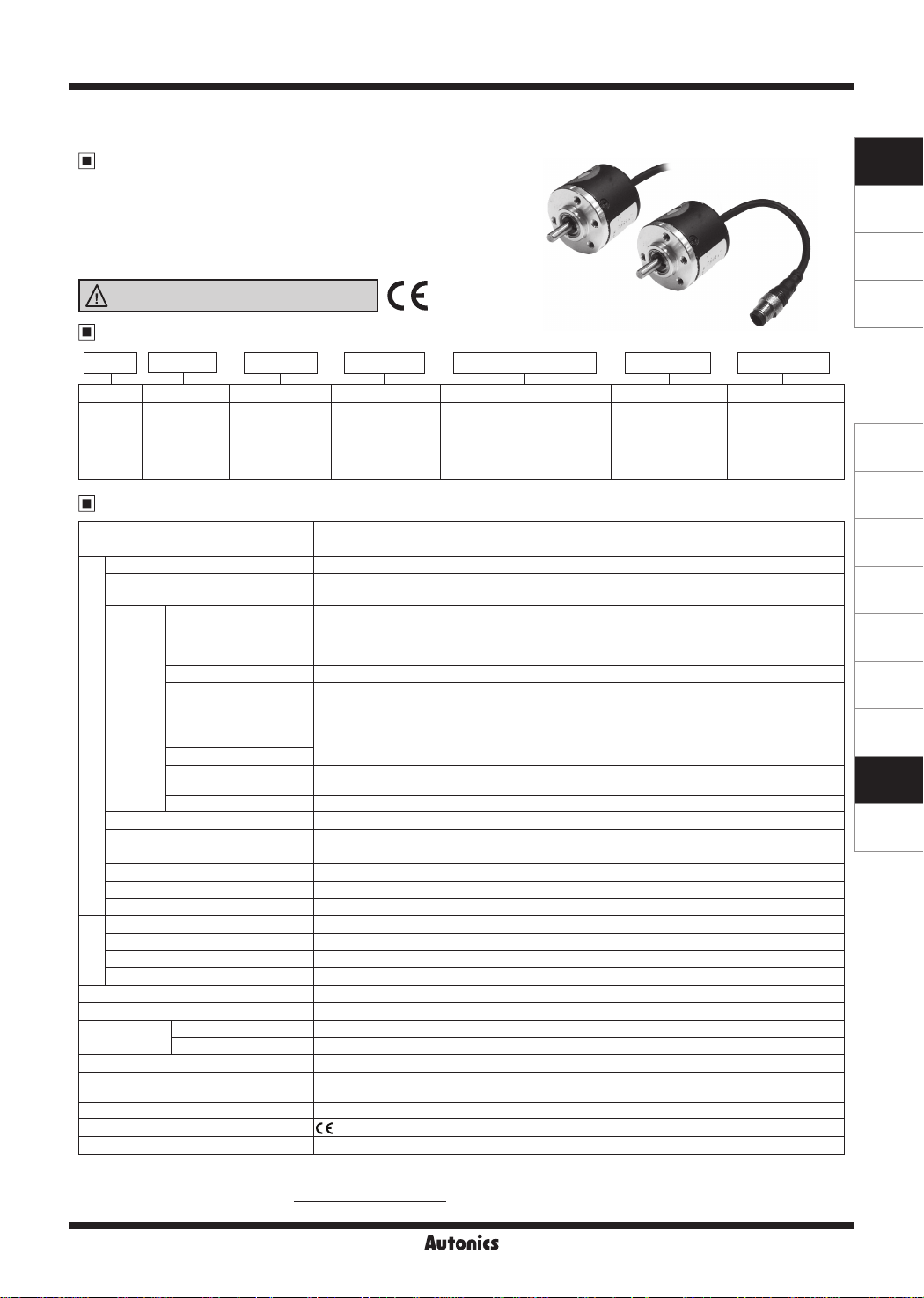
E30S Series
Shaft Type Ø30mm Incremental Rotary Encoder
Features
● Ø30mm of miniature shaft type rotary encoder
● Easy installation at narrow space
● Low moment of inertia
● Power supply: 5VDC, 12-24VDC ±5%
● Various output types
Please read “Safety Considerations”
in the instruction manual before using.
=l&
____
Ordering Information
~
E30S
I
I
Series Shaft diameter Pulses/revolution Output phase Control output Power supply Cable
Ø30mm,
shaft type
Specifications
Item Shaft type Ø30mm Incremental Rotary Encoder
Resolution (PPR)
Output phase A, B, Z phase (line driver: A, A_, B, B_, Z, Z_ phase)
Phase dierence of output
Control
output
Response
time
(rise/fall)
Electrical specication
Max. response frequency 300kHz
Power supply • 5VDCᜡ ±5% (ripple P-P: max. 5%) • 12-24VDCᜡ ±5% (ripple P-P: max. 5%)
Current consumption
Insulation resistance Over 100MΩ (at 500VDC megger between all terminals and case)
Dielectric strength 750VAC 50/60Hz for 1 minute (between all terminals and case)
Connection Axial cable type, axial cable connector type
Starting torque Max. 20gf·cm (0.002N·m)
Moment of inertia Max. 20g·cm
Shaft loading Radial: max. 2kgf, Thrust: max. 1kgf
Max. allowable revolution
Mechanical
specication
Vibra ion 1.5mm amplitude at frequency of 10 to 55Hz (for 1 min) in each X, Y, Z direction for 2 hours
Shock Approx. max. 50G
Environment
Protec ion structure IP50 (IEC standard)
Cable
Accessory Ø4mm coupling
Approval
Unit weight Approx. 80g
※
1: Not indicated resolutions are customizable. ※Environment resistance is rated at no freezing or condensation.
※
Make sure that max. response revolution should be lower than or equal to max. allowable revolution when selecting the resolution.
2:
[Max. response revolution (rpm)=
4
I
I
I
Ø4mm
※
1
Totem pole output
NPN open collector output Load current: max. 30mA, residual voltage: max. 0.4VDC
Voltage output Load current: max. 10mA, residual voltage: max. 0.4VDC
Line driver output
Totem pole output
NPN open collector output
Voltage output
Line driver output Max. 0 5
Ambient temperature -10 to 70℃, storage: -25 to 85
I
Ambient humidity 35 to 85%RH, storage: 35 to 90%RH
I
Resolution
3000 3 N 24
1-1
I
100, 200, 360,
500, 1000, 1024,
3000
※
2
Max. response frequency
____.I
CE:
1-1
3: A, B, Z
6: A, A_, B, B_, Z, Z
100, 200, 360, 500, 1000, 1024, 3000
Phase dierence between A and B:
4
• [Low] - Load current: max. 30mA, residual voltage: max. 0.4VDC
• [High] - Load current: max. 10mA,
Output voltage (power voltage 5VDCᜡ): min. (power voltage-2.0)VDCᜡ,
Output voltage (power voltage 12-24VDCᜡ): min. (power voltage-3.0)VDC
• [Low] - Load current: max. 20mA, residual voltage: max. 0.5VDCᜡ
• [High] - Load current: max. -20mA, output voltage: min. 2.5VDCᜡ
Max. 1
㎲ (
Max. 1㎲ (5VDC: output resistance 820Ω), Max. 2㎲ (12-24VDC: output resistance 4.7kΩ)
cable length: 2m, I sink = 20mA)
(
㎲ (
Max. 80mA (disconnection of the load), Line driver output: max. 50mA (disconnection of he load)
5,000rpm
Ø5mm, 5-wire (line driver: 8-wire), 2m, Shield cable
WG24, core diameter: 0.08mm, number of cores: 40, insulator out diameter: Ø1mm)
(A
(except line driver output)
CE:
1-1
I
T: Totem pole output
N: NPN open collector output
_
V: Voltage output
L: Line driver output (※)
※
The power of Line driver is only for 5VDC.
cable length: 2m, I sink = 20mA)
cable leng h: 2m, I sink = 20mA)
2
(2×10
-6
kg·m
2
)
× 60 sec]
I
T ± T
_
8
℃
1-1
5: 5VDC ±5%
24: 12-24VDC ±5%
_
(T=1 cycle of A phase)
ᜡ
ᜡ
1-1
I
ᜡ
I
No mark
: axial cable type
C: axial cable
connector type
ᜡ
Autonics
I
H-21
SENSORS
CONTROLLERS
MOTION DEVICES
SOFTWARE
(A)
Photoelectric
Sensors
(B)
Fiber Optic
Sensors
(C)
LiDAR
(D)
Door/Area
Sensors
(E)
Vision
Sensors
(F)
Proximity
Sensors
(G)
Pressure
Sensors
(H)
Rotary
Encoders
(I)
Connectors/
Connector Cables/
Sensor Distribution
Boxes/ Sockets
Page 2
E30S Series
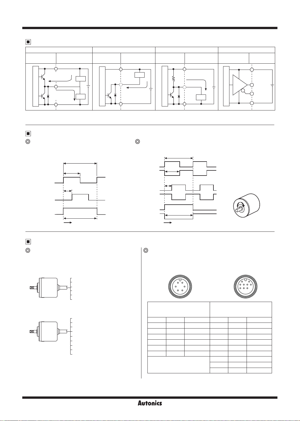
Control Output Diagram
Totem pole output NPN open collector output Voltage output Line driver output
Rotary encoder
circuit
Main circuit
● The output circuit of A, B, Z phase are same. (line driver output is A, A_, B, B_, Z, Z_ )
● Totem pole output type can be used for NPN open collector output type (※1) or Voltage output type (※2).
Load connection
+V
Sink current
: max. 30mA
Output
Source current
: max. 10mA
0V
※
Load
※
Load
Rotary encoder
circuit
1
+
-
2
Main circuit
Load connection
+V
Load
Output
Sink current
: max. 30mA
0V
Rotary encoder
circuit
+
-
Main circuit
Load connection
+V
Source current
: max. 10mA
R
Output
0V
Load
Rotary encoder
circuit
+
-
Main circuit
Load
connection
+V
A phase
output
_
phase
A
output
0V
+
-
Output Waveform
Totem pole output /
NPN open collector output /
Voltage output
T
T ± T
_
_
4
2
A phase
B phase
Z phase
h
H
T ± T
L
~
4_ 8
~
H
L
~
' '
H
L
~
_
T ±
2
Clockwise (CW)
·1
'
:
T
_
Line driver output
T
T ± T
_
_
2
4
+--------+ '
T ± T
_
' '
' '
4_ 8
' '
T
_
T ±
2
Clockwise (CW)
A phase
_
phase
A
B phase
_
B
phase
Z phase
_
Z
phase
H
L
~
H
L
~
H
L
~
H
~
L
H
L
7,
H
L
'
'
.;
CW
@)
-
~~------=-=-_____::_~
Connections
Axial cable type Axial cable connector type
~
Totem pole output /
●
NPN open collector output /
Voltage output
Black: OUT A
White: OUT B
Orange: OUT Z
Brown: +V (5VDC, 12-24VDC ±5%)
Blue: GND (0V)
Shield: F.G.
● Line driver output
Black: OUT A
Red: OUT A
White: OUT B
Gray: OUT B
Orange: OUT Z
Yellow: OUT Z
Brown: +V (5VDC ±5%)
Blue: GND (0V)
Shield: F.G.
※
Unused wires must be insulated.
※
The metal case and shield wire of encoder should be grounded (F.G.).
※
Do not apply tensile streng h over 30N to the cable.
_
_
_
● Totem pole output /
• Line driver output
NPN open collector output /
Voltage output
152
3 6
4
Totem pole output
NPN open collector output
Voltage output
Pin No. Func ion Cable color Pin No. Function Cable color
① OUT A Black ① OUT A Black
② OUT B White ② OUT A Red
③ OUT
④ +V Brown ④ GND Blue
⑤ GND Blue ⑤ OUT B White
⑥ F.G. Shield ⑥ OUT B Gray
-
※
F.G. (field ground): It should be grounded separately.
Z Orange ③ +V Brown
Line driver output
⑦ OUT Z Orange
⑧ OUT Z Yellow
⑨ F
21
543
6
7 8 9
.G. Shield
H-22
Autonics
Page 3

Incremental Ø30mm Shaft type
Dimensions
Axial cable type
3-120°
4-M3
DP: 5
Ø22.5
3.5
JL
Ø30
0
Ø15
-0.007
-0.017
Ø4
-0.1
I
Axial cable connector type
3-120°
4-M3
DP: 5
3.5
Ø22 5
※
Connector cable is sold separately and refer to the 'Connectors, Connector
Cables, Sensor Distribution Boxes, Sockets' section.
JL
Ø30
0
-0.007
-0.1
Ø15
-0.017
Ø4
Coupling (E30S)
Ø13
+0.1
Ø4
+0.05
※
It must not use larger shaft loading than specification.
※
Do not put strong impact when insert a coupling into shaft.
Failure to follow this instruction may result in product damage.
※
Fix the unit or a coupling by a wrench under 0.15N m of torque.
※
When you install this unit, if eccentricity and deflection angle are larger, it may shorten the life cycle of this unit.
※
For parallel misalignment, angular misalignment, end-play terms, refer to the "Glossary" section of Technical Description.
※
For flexible coupling (ERB series) information, refer to the ERB series section.
21
2.72.7
Parallel misalignment: max. 0 25mm
Angular misalignment: max. 5°
4-M3
End-play: max. 0.5mm
0
3
11.2
-0.1
6
i.-.
r5<'
Cable for axial cable type
Ø5, 5-wire (line driver output: 8-wire),
2m, Shield cable
0
3
11.2
-0.1
6
Cable for axial cable connector type
Ø5, 5-wire (line driver output: 8-wire),
250mm, Shield cable
3.728.3
L
l
3.7 25028.3
Ø5, 2m
~
\
(unit: mm)
M17×1
SENSORS
CONTROLLERS
MOTION DEVICES
SOFTWARE
(A)
Photoelectric
Sensors
(B)
Fiber Optic
Sensors
(C)
LiDAR
(D)
Door/Area
Sensors
(E)
Vision
Sensors
(F)
Proximity
Sensors
(G)
Pressure
Sensors
(H)
Rotary
Encoders
(I)
Connectors/
Connector Cables/
Sensor Distribution
Boxes/ Sockets
Autonics
H-23
 Loading...