

Page 1
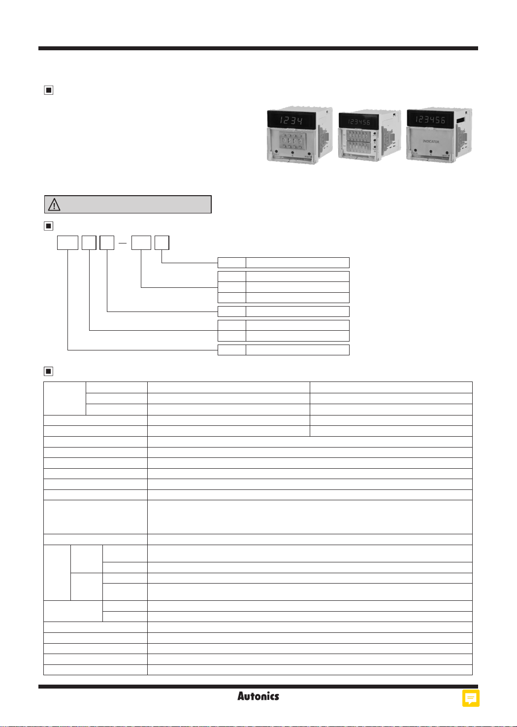
FM Series
DIN W72×H72mm Up·Down Measure Counter
Features
● Parameter Setting
: Input/Output operation mode, Max. counting speed,
Decimal point position, OUT1/2 time (0.01 to 99.99 sec),
Selectable voltage input (PNP) method or no-voltage input
(NPN) method, Selectable Multiply or Divide mode function.
● Memory protection for 10 years
(using non-voltage semiconductor)
● Power supply: 100-240VAC 50/60Hz
● Built-in Microprocessor
Please read “Safety Considerations”
in the instruction manual before using.
ᜢᜧ
Ordering Information
1PFM 4 4M
Power supply
Output
Function
Display digit
Size
4 100-240VAC 50/60Hz
1P
1-stage setting
2P 2-stage setting
I Indicator
M Measure func ion
4 9999 (4-digit)
6 999999 (6-digit)
FM DIN W72×H72
mm
Specications
1-stage setting FM4M-1P4 FM6M-1P4
Model
Display digit 4-digit 6-digit
Character size (W×H) 6×10mm 4×8mm
Power supply 100-240VACᜠ 50/60Hz
Permissible voltage range 90 to 110% of rated voltage
Power consumption ●1-stage: max. 4.6VA ●2-stage: max. 5.8VA ●Indicator: max. 3.8VA
Max. counting speed of CP1/CP2 Selectable 1cps / 30cps / 300cps / 2kcps / 5kcps
Return ime Max. 500ms
Min. signal wid h RESET: approx. 20ms
Input method
One-shot output time 0.01 to 99.99 sec
Control
output
Relay
life cycle
Insulation resistance Over 100MΩ (at 500VDC megger)
External power supply Max. 12VDCᜡ±10% 50mA
Memory retention Approx. 10 years (non-volatile memory)
Dielectric strength 2,000VAC 50/60Hz for 1 min (between all terminals and case)
Noise immunity ±2kV he square wave noise (pulse width 1㎲) by noise simulator
2-stage setting FM4M-2P4 FM6M-2P4
Indicator FM4M-I4 FM6M-I4
Selectable voltage input (PNP) method or no-voltage input (NPN) method
[Voltage input (PNP) method]-input impedance: max. 10.8kΩ, [H]: 5-30VDCᜡ, [L]: 0-2VDC
[No-voltage input (NPN) method]-short-circuit impedance: max. 470Ω, short-circuit residual voltage: max. 1VDC,
open-circuit impedance: min. 100kΩ
Contact
Solid
state
Type
Capacity 250VACᜠ 3A, 30VDCᜡ3A resistive load
Type ●1-stage: 1 NPN open collector ●2-stage: OUT1-1 NPN open collector, OUT2-1 NPN open collector
Capacity
Mechanical Min. 5,000,000 operations
Electrical Min. 100,000 operations (250VAC 3A resistive load)
●1-stage: Instantaneous SPDT (1c)
● 2-stage: Instantaneous OUT1-SPST (1a), Instantaneous OUT2-SPST (1a)
NPN open collector output
●Load voltage: max. 30VDCᜡ ●Load current: max. 100mA ●Residual voltage: max 1VDC
ᜡ
M-94
Autonics
Page 2
Up·Down Measure Counter
Specications
1-stage setting FM4M-1P4 FM6M-1P4
Model
Vibra ion
Shock
Environment
Protec ion structure IP20 (front part, IEC standard)
Approval
Weight
※
1: The weight includes packaging. The weight in parenthesis is for unit only.
※
Environment resistance is rated at no freezing or condensation.
2-stage setting FM4M-2P4 FM6M-2P4
Indicator FM4M-I4 FM6M-I4
Mechanical 0.75mm amplitude at frequency 10 to 55Hz (for 1 min) in each X, Y, Z direction for 1 hour
Malfunc ion 0.5mm amplitude at frequency 10 to 55Hz (for 1 min) in each X, Y, Z direction for 10 min
Mechanical 300m/s
Malfunc ion 100m/s
Ambient temp. -10 to 55℃, storage: -25 to 65
2
(approx. 30G) in each X, Y, Z direction for 3 times
2
(approx. 10G) in each X, Y, Z direction for 3 times
℃
Ambient humi. 35 to 85%RH, storage: 35 to 85%RH
1-stage setting Approx. 245g (approx. 180g)
ᜢᜧ
※
1
2-stage setting Approx. 265g (approx. 200g)
Indicator Approx. 225g (approx. 160g)
SENSORS
CONTROLLERS
MOTION DEVICES
SOFTWARE
(J)
Temperature
Controllers
Connections
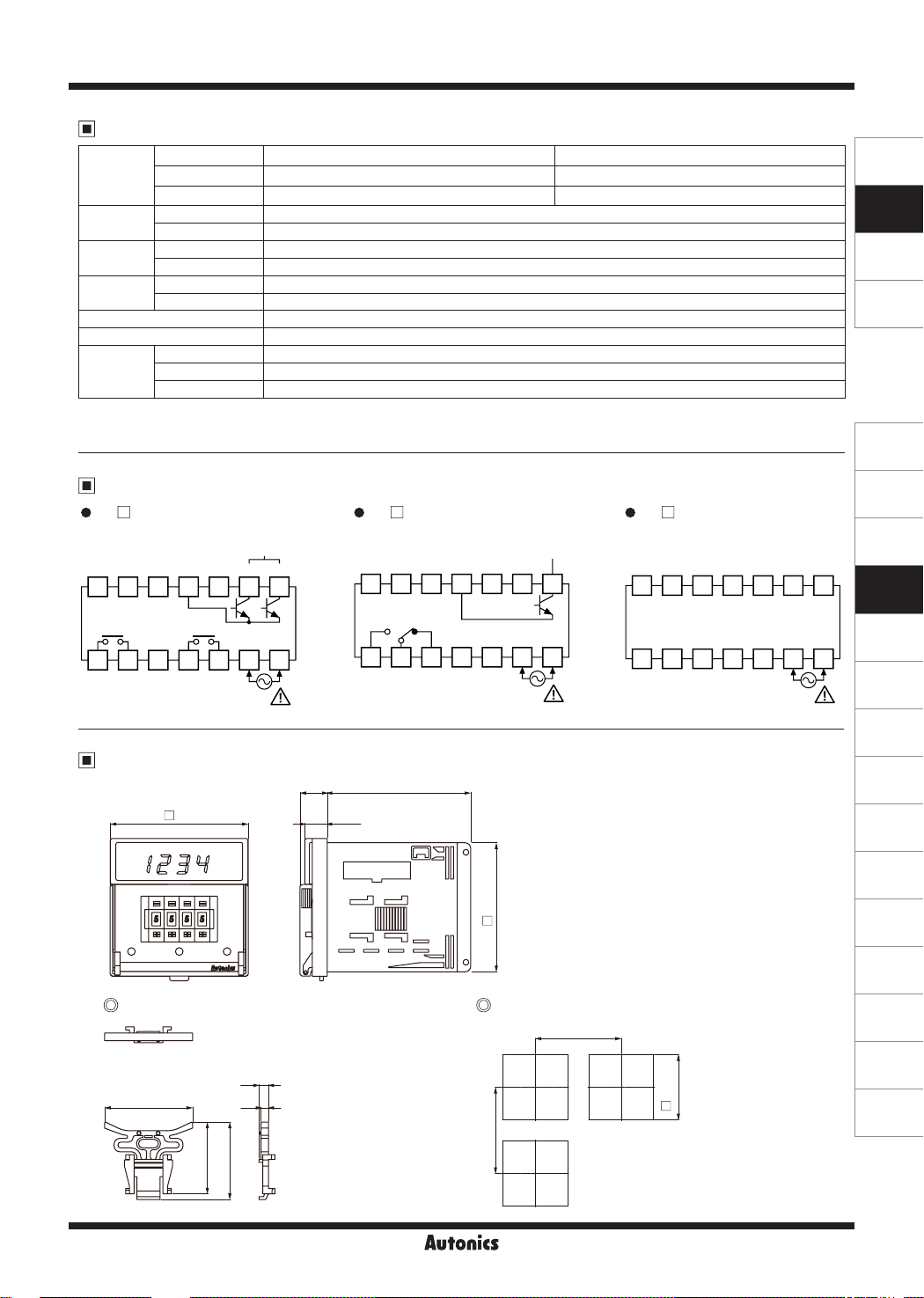
FM M-2P4
12VDC
CP2
CP1
9
OUT1
1
CONTACT
250VAC 3A, 30VDC 3A
RESISTIVE LOAD
0VDC
50mA
10
11
2
3
Dimensions
72
□
0 0 0
SOL D STATE OUT
RESET
128
OUT2
4
5
SOURCE
100-240VAC
50/60Hz 5.8VA
30VDC 100mA
OUT1
OUT2
14
13
6
7
FM M-1P4
•
□
12VDC
CP2
50mA
9
10
OUT
1
2
75
14.3
CP1
CONTACT
250VAC 3A, 30VDC 3A
RESISTIVE LOAD
11.8
c:=J~~~
c::::'J c::::'J
I~
1,
I~
-.,,
lfflill
=~~~~
3
0VDC
11
4
SOURCE
100-240VAC
50/60Hz 4.6VA
0
0
SOL D STATE OUT
30VDC 100mA
RESET
13
128
5
6
67.5
□
(K)
FM M-I4
•
□
12VDC
CP2
14
7
CP1
9
1
0VDC
50mA
10
2
3
RESET
128
11
4
5
SOURCE
100-240VAC
50/60Hz 3 8VA
13
6
(unit: mm)
SSRs
(L)
Power
Controllers
(M)
14
Counters
(N)
Timers
7
(O)
Digital
Panel Meters
(P)
Indicators
(Q)
Converters
(R)
Digital
Display Units
(S)
Sensor
Controllers
(T)
Switching
Mode Power
Supplies
(U)
Recorders
51
[?
46 4
37.5
40.5
Panel cut-out Bracket
Min. 90
5
+0.7
68
□
0
(V)
HMIs
(W)
Panel PC
(X)
Field Network
Devices
Min. 90
Autonics
M-95
Page 3

FM Series
Input Connections
Voltage input (PNP)
● Solid-state input (standard sensor: PNP output type sensor) ● Contact input
Sensor
(PNP output)
※
CP1, CP2, RESET input part
Brown
Black
※
Blue
+12V
Inner circuit
10.8kΩ
0V
SensorCounter
(PNP open collector
output)
Brown
Black
Blue
Counter
+12V
※
Inner circuit
10.8kΩ
0V
※
No-voltage input (NPN)
● Solid-state input (standard sensor: NPN output type sensor) ● Contact input
Counter
※
Counting speed
: Set as 1 or 30cps
+12V
Inner circuit
10.8kΩ
0V
Sensor
(NPN output)
※
CP1, CP2, RESET input part
Brown
Black
※
Blue
Counter
+12V
5.4kΩ
Inner circuit
0V
Sensor
(NPN open collector
output)
Brown
Black
Blue
Counter
+12V
5.4kΩ
※
Inner circuit
0V
※
Counter
+12V
※
5.4kΩ
Inner circuit
0V
Counting speed
: Set as 1 or 30cps
Input & Output Connections
When operation load by sensor power When operating load by external power
(+)
Constant-voltage
(-)
Load1
PR18-5DP
Load1
8 9 10 11 12 13 14
CP1 CP2
12VDC
0VDC
N.O. N.C.
COM
1 2 3 4 5 6 7
※
8 9 10 11 12 13 14
CP1 CP2
N.O. N.C.
12VDC
COM
0VDC
1 2 3 4 5 6 7
circuit
(power for
operating load)
Load2
SOURCE
● The sum of operating current capacity of load 1 and
sensor should not be over external power capacity
(50mA).
M-96
(power for
operating load)
Load2
SOURCE
● The capacity of load 1 should not be over transistor
switching capacity (max. 30VDC, 100mA)
● Do not supply the reverse polarity power.
※
when using inductive load (relay, etc.), connector surge
absorber at both ends of the load 1
Autonics
Page 4
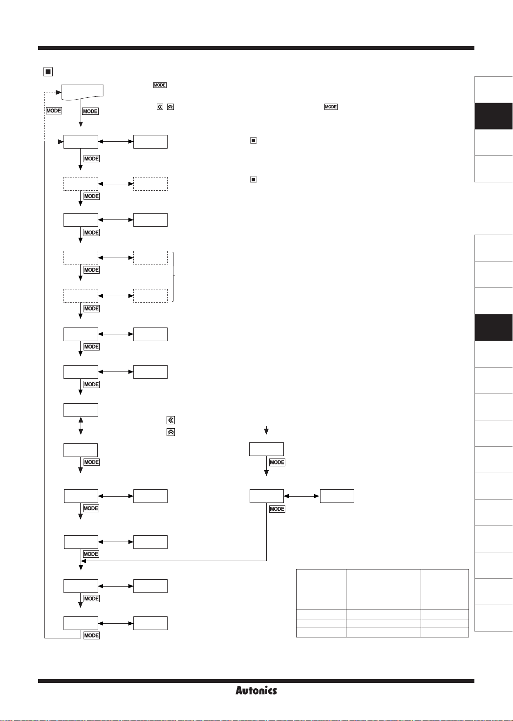
Parameter Setting
※
RUN mode
3 sec
Input operation mode
InM UD-A
Output operation mode
·--------------------
OUtM F
------
i~
Max. counting speed
CPS 30
I
i
lMODEI
OUT2 output time
OUT2 0)50
i
______
i~
OUT1 output time
OUT1 HOLD
: i
-~
Hold the key for 3 sec to save the setting value and return to RUN mode after changing the setting value.
※
If there is no key input for 60 sec while setting the parameters, the new settings are ignored, and the unit returns
to RUN mode with previous settings.
※
Press the
3 sec
to save the setting value and move to the next parameter.
※
The dotted line parameters may not appear depending on output specications or other parameter settings.
※
1: Each parameter and corresponding setting value will ash alternately every 0.5 se
Flashes
※1
alternately
,._,,._~►
·--------------------·
:
·--------------------'
--I..
-----
►
L__I
►
:
..
___________________
..
Up·Down Measure Counter
, keys to select or set the desired value. Press the
Setting range: Refer to '
Setting range: Refer to '
※
Does not appear in indicator model.
Setting range: 1, 30,
___J
_
Setting range: ●
※
In case of F, N, S output operation mode,
※
In case of
※
1-stage setting model displays only
OUT2 (OUtT
●
OUT1: HOLD
S
output operation mode for 2-stage setting,
Input Operation Mode'.
Output Operation Mode'.
(2,000), 5K (5,000)
300, 2K
): 00 01 to 99.99 sec
, 00.01 to 99.99 sec
OUtT
key once after changing the setting value,
c
.
OUT2 (OUtT
.
) does not appear.
OUT1
does not appear.
SENSORS
CONTROLLERS
MOTION DEVICES
SOFTWARE
(J)
Temperature
Controllers
(K)
SSRs
(L)
Power
Controllers
Decimal point position
DP ----
--1 ..
'----------,i-lMO-----'DEI
Input logic
'----------,~
Mode setting
-
SIG PNP
--
I"
-
i
lMODEI
--►~I------'
--
►
~I------'
※
In case of multiply mode of 6-digit model, decimal point is available up to 3rd digit.
Setting range:
Setting range:
------/ -----.-/ ----.--/ ---.---
(voltage input),
PNP
(no-voltage input)
NPN
M-D
※
Multiply mode
2
Divide mode
※
MULT
Decimal point position
for prescale
ScDP
Setting value for
multiply mode
mSCL
Memory backup
DATA REC
'--------;___JI
Front RESET key
+
IMODEI
..
-.---
※
Disable to set it smaller than
decimal point position [DP] setting.
!000
►
L_I
RStB ON
'--------------"
※
2: Multiply mode [
※
3: Divide mode [
IMODEI
]: Displayed by multiplying input signal and setting value.
Input signal×Setting value=Display value (input signal: 1, setting value: 4, it displays 4(1×4))
Input signal/Setting value=Display value (input signal: 4, setting value: 4, it displays 1(4/4))
M U LT
]: Displays 1 when input signals are input as the setting value.
D IV
Setting range
: Refer to the note (※4).
Setting range
: Refer to the note (※4).
Setting range
:
(memory backup),
_
REC
_J
(reset count value at power failure)
CLR
Setting range
: ON (available front RESET key),
(unavailable front RESET key)
OFF
Divide mode
setting value
3
DIV
dSV 0001
※
4
Decimal
point position
[DP]
---- ----/ ---.-/ --.--/ -.---
---.- ---.-/ --.--/ -.---
--.-- --.--/ -.---
-.--- -.---
Autonics
Setting range
: 1 to 9999
Prescale decimal
point position
[
ScDP
(M)
Counters
(N)
Timers
(O)
Digital
Panel Meters
(P)
Indicators
(Q)
Converters
(R)
Digital
Display Units
(S)
Sensor
Controllers
(T)
Switching
Mode Power
Supplies
(U)
Recorders
(V)
Setting value
for multiply
]
mode
[
]
mSCL
0.001 to 9999
0.001 to 999.9
0.001 to 99 99
0.001 to 9.999
HMIs
(W)
Panel PC
(X)
Field Network
Devices
M-97
Page 5
FM Series
Measure Counter
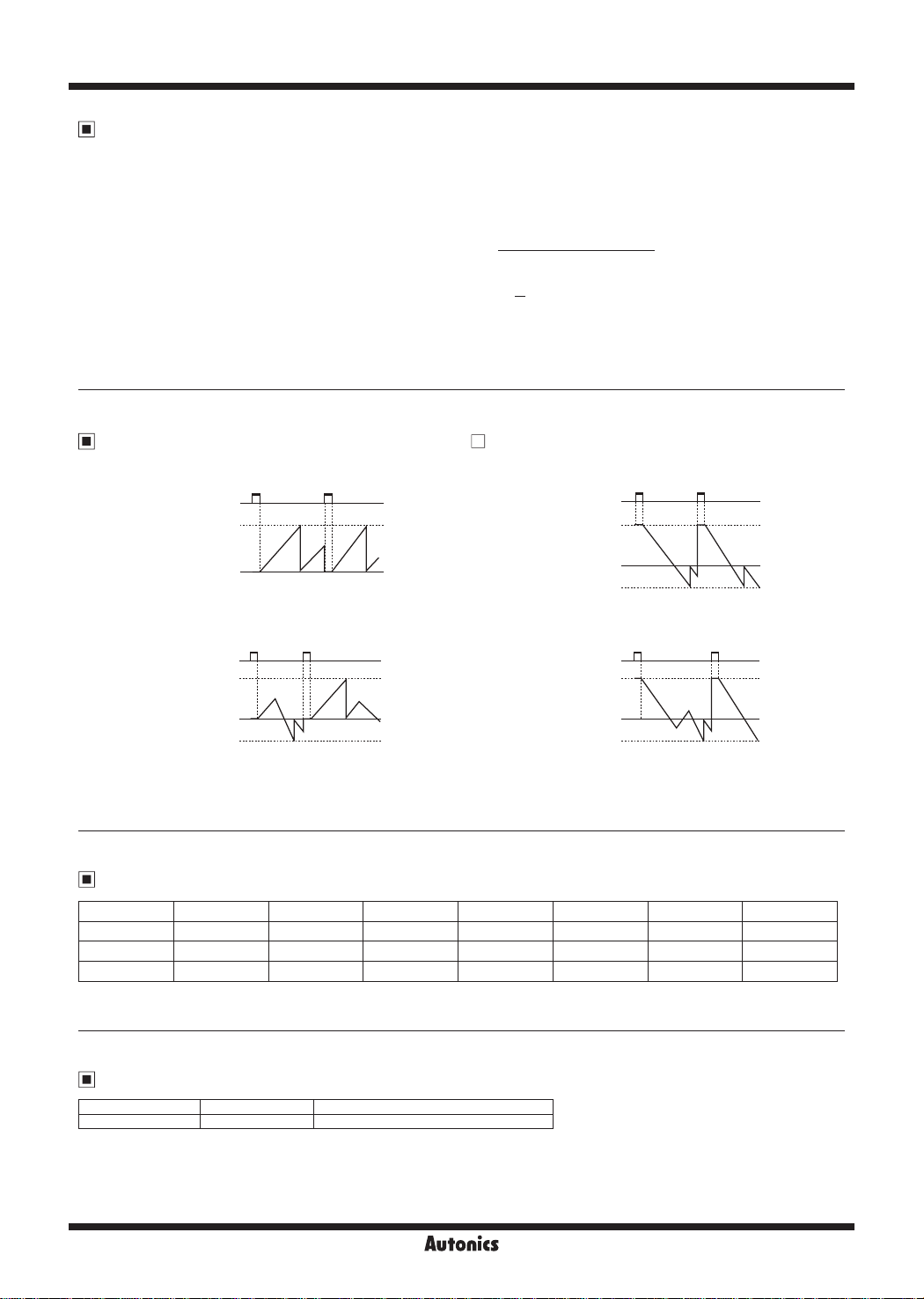
Measure counter sets multiply or divide integer per 1 pulse input.
● Multi Mode
It multiplies the inner SW3 setting value at a count input
signal and displays it.
Input signal (N)×Multi Mode preset value=Indication value
N × 4 = 4, 8, 12 … ( N=1, 2, 3 ‥ )
∴
● Divide Mode
It displays as 1 when the count input signal is entered as
preset value of inner SW3.
Input signal (N)
Divide Mode preset value
N
= 1, 2, 3 … ( N=5, 10, 15 ‥ )
∴
5
※
Please be cautious the error can occur when down count
is executed during up count.
= Indication value
Counting Operation for Indicator (FM M-I4)
● Input mode: Up
RESET
+Max. display value
0
● Input mode: Up / Down-A, B, C
RESET
+Max. display value
0
-Max. display value
※
- display is only for F, K, Q, S output operation mode and it cannot be set.
□
● Input mode: Down
RESET
+Max. display value
-Max. display value
● Input mode: Up / Down-D, E, F
RESET
+Max. display value
-Max. display value
n n
0
....
~
0
Factory Default
Parameter Default Parameter Default Parameter Default Parameter Default
InM UD-A OUT2 0)50 SIG PNP mSCL !000
OUtm F OUT1 HOLD M-D MULT DATA REC
CPS 30 DP ---- ScDP -.--- RStB ON
Error Display and Output Operation
Error Display Error description Troubleshooting
ERR0
※
When error occurs, the output turns OFF.
※
When 1st setting value is set as 0 (zero), OUT1 maintains OFF.
When 2nd setting value is smaller than 1st setting value, 1st setting value is ignored and only OUT2 output operates.
※
Indicator model does not have error display function.
M-98
Setting value is 0. Change the setting value anything but 0.
Autonics
Page 6
Up·Down Measure Counter
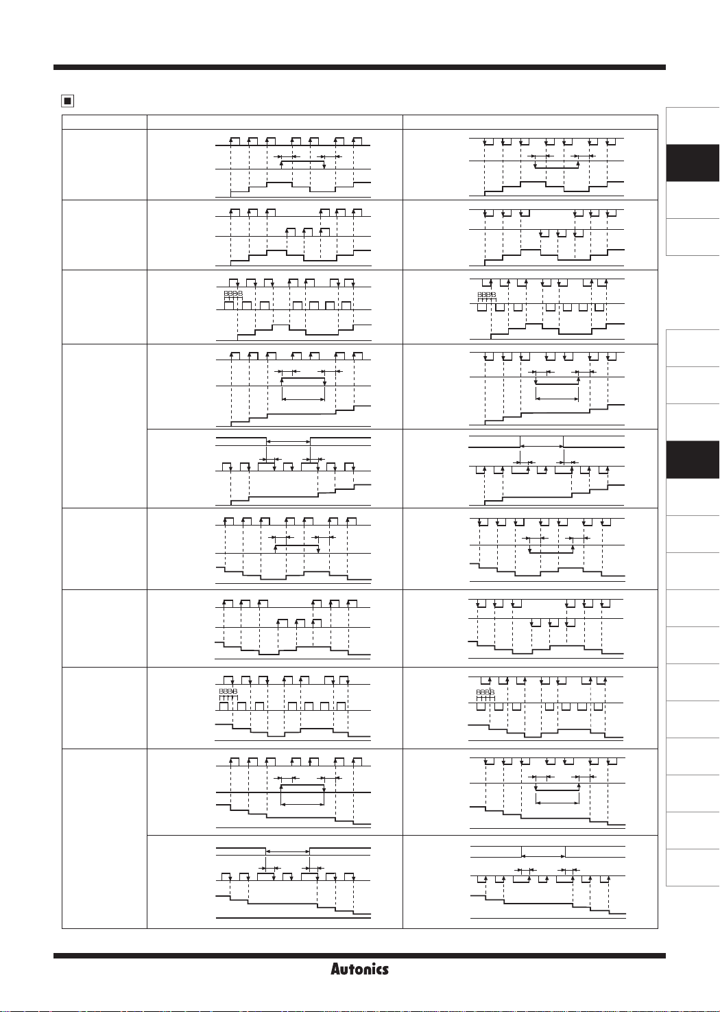
Input Operation Mode
※
CP: Clock Pulse
Input mode Voltage input (PNP) method No-voltage input (PNP) method
H
CP1
L
Up/Down-A
command input
[
]
UD-A
Up/Down-B
individual input
[
]
UD-B
Up/Down-C
phase dierence
input
[
]
UD-C
Up adding input
[UP]
Up/Down-D
command input
[
]
UD-D
Up/Down-D
individual input
[
]
UD-E
CP2
Count
CP1
CP2
Count
CP1
CP2
Count
CP1
CP2
Count
CP1
CP2
Count
CP1
CP2
Count
CP1
CP2
Count
CP1
Up/Down-F
phase dierence
input
[
]
UD-F
CP2
Count
CP1
CP2
Count
Down
subtracting input
[DN]
※
A: over min. signal width, B: over han 1/2 of min. signal width. If the signal is smaller than these width, it may cause counting error (±1).
CP1
CP2
Count
f7f7fl
H
L
I I I I I I
1
0
H
L
f7 f7 f7 f7 f7 f7
H
L
I I I I I I
I I I I I I I
1
0
H
qqq
L
BBBB
r-t"rr-1 ' '
H
□'□'□'
L
: : : : : : :
1
0
~
H
L
f7f7f7
'
'
'
H
L
H
L
H
L
H
L
H
L
0
H
L
H
L
0
H
L
H
L
0
H
L
H
L
H
L
H
L
0
'
'
'
'
'
'
'
'
'
'
'
'
1
0
~
on
I I I I I
1
'-----------'~
0
~
f7 f7 f7 f7 f7 f7
n
n-1
n-2
~
f7 f7 f7
I I I I I
I : I
: : : I : : : :
n
n-1
n-2
qqq
BBBB I I I I I I
tttt"11111
□:□:□:
I I I I I I
I I I I I I I
n
n-1
flflf7
I I I I I
: : :
I I I I I
' ' ' f l I '
n
n-1
~
0
n
n-1
f7f7
A A
:
~
' . . '
3
2
2
I I
2
h
3
3
2
'
...,....,..-
'
'
• •
I.
'
'
No counting
A
2
A
n-3
2
non:
2
f7fl
2
nn
A
No counting
3
□
a--o
n-2
PfJO:
n-1 n-1
n-2
n-3
f7f7
:n:n
n-2
n-2
n-3
nn
A
~
No counting
n-2
n-3
No counting
A
n-2
:
.........+
1
1
1
QQ
1
A
~
.I
A
3
A
n-1
fl
f7
QQ
n:n:
n-1
A
~
A
n-3
f7f7
2
2
2
f7f7
'
'
'
'
'
'
'
'
'
4
,........r-
n
4
fl
n-2
n-3
fl
:
n-2
n-3
11
n-2
n-3
f7f7
I
n-4
n-4
3
3
3
5
5
n-5
n-5
H
CP1
CP2
Count
CP1
CP2
Count
CP1
CP2
Count
CP1
CP2
CP1
CP2
CP1
CP2
Count
CP1
CP2
Count
CP1
CP2
Count
CP1
CP2
Count
CP1
CP2
Count
UUU
L
I I I I I I
H
; I
L
I I I I I
1
0
H
uuu
L
H
L
: ! :
I I I I I I I I
1
0
H
L
L..f L..f L..f
~
H
0,0,0,
L
I I I I I I
1
0
~
H
L
t--JLit--J
H
: :
L
: I :
Count
Count
: '
1
0
r:::::::.r:::::
H
L
H
L
L..f
Lt
:
~:
1
~-
0
H
uuu
L
H
L
: : :
n
n-1
n-2
0
H
L
H
: , :
L
I I I I I I I I
I I I I I I I
1
n
n-1
n-2
0
H
L
H
L
□:□:
I I I I I I I
n
n-1
0
H
L
µµ,
I I I
H
L
: : : I I : :
n
n-1
~
0
H
L
H
□□
L
I I I I I
n
n-1
--LL______--L__
0
LIU LIU
A A
;T;
2
2
2
3
:
3
t--J
uu
3
A
2
LIµ!
2
' '
2
LILI
:TT;
1 1
!1?:
No counting
I.
3
~:
-----~~
2
No counting
I I
A
LJ
-----~[
~
n-3
n-3
□:
n-2
p
I ,I, 4 I I
n-2
I I
A
---i---r-
LJ□LJ
A
□
q
2
Liu
I I I I
A
:
----r-----r-
.I,
I I f : :
n-1
n-2
uuu
uutJ::
n-1 n-1
n-2
:w:u
n-2
n-3
uu
A
---r-----r-
No counting
n-3
No counting
A
----r-,+-
n-2
1
uuu
qq
1
t--Jp
A
TT:
.1
: :
L..f L..f
3
~
~
LIU
A
n-2
n-2
w:w:
n-1
pu
A
---,------f+
□□
n-3
3
2
!
3
2
'
3
2
5
4
5
4
n-3
n-3
n-2
n-3
:
n-4
n-5
n-4
n-5
SENSORS
CONTROLLERS
MOTION DEVICES
SOFTWARE
(J)
Temperature
Controllers
(K)
SSRs
(L)
Power
Controllers
(M)
Counters
(N)
Timers
(O)
Digital
Panel Meters
(P)
Indicators
(Q)
Converters
(R)
Digital
Display Units
(S)
Sensor
Controllers
(T)
Switching
Mode Power
Supplies
(U)
Recorders
(V)
HMIs
(W)
Panel PC
(X)
Field Network
Devices
Autonics
M-99
Page 7
FM Series
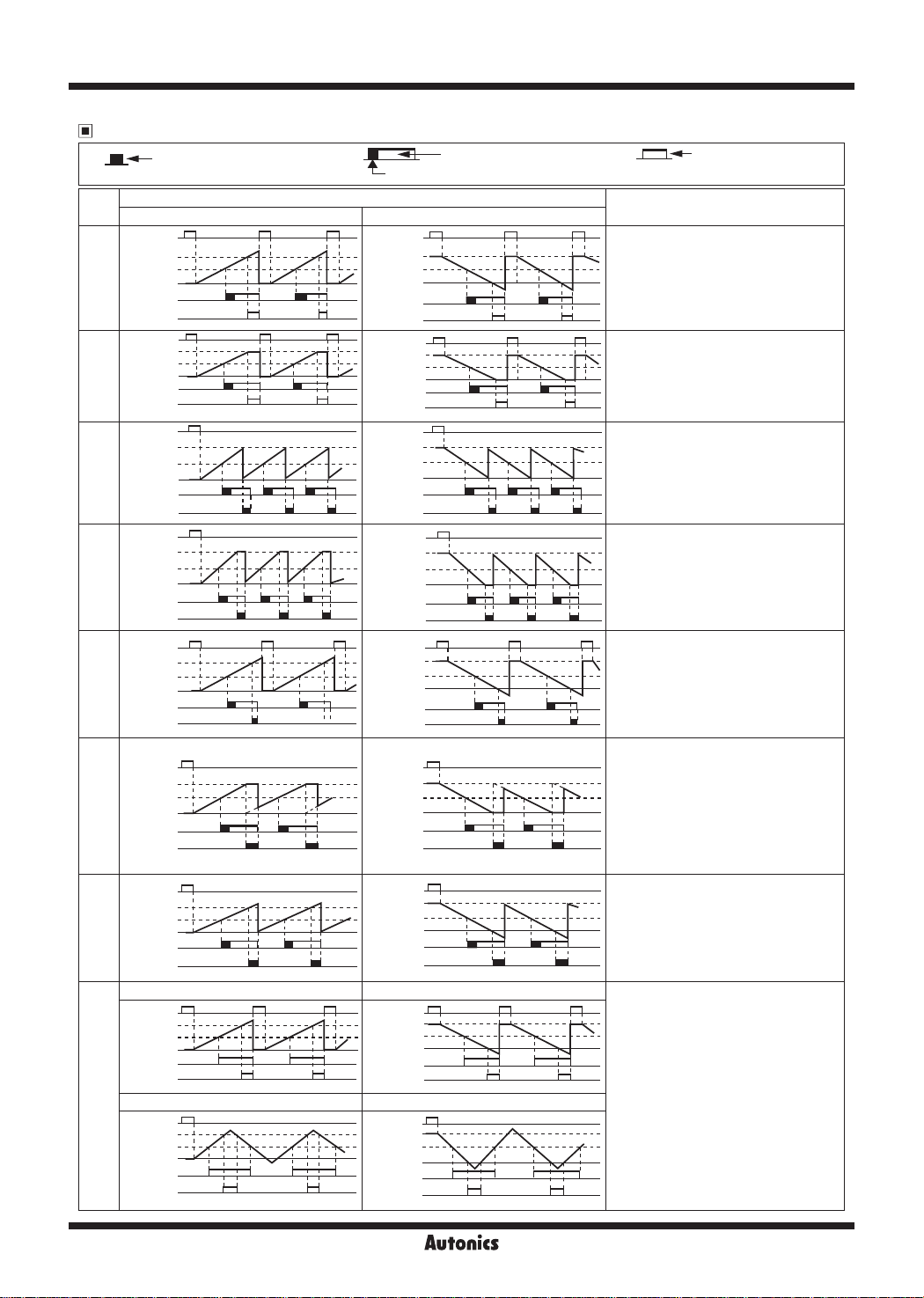
Output Operation Mode
00
One-shot output of OUT2
(0.01 to 99 99 sec)
I
-----
Input mode
Output
mode
Up, Up/Down-A, B, C
RESET
2nd setting
F
[F]
N
[N]
C
[C]
R
[R]
K
[K]
P
[P]
Q
[Q]
S
[S]
1st setting
0
OUT1
OUT2
(OUT)
RESET
2nd setting
1st setting
0
OUT1
OUT2
(OUT)
r-,
RESET
2nd sett ng
1st sett ng
---Gd2121--
0
OUT1
OUT2
(OUT)
r-,
RESET
2nd setting
1st setting
---~~--
0
OUT1
OUT2
(OUT)
RESET
2nd setting
1st setting
0
OUT1
OUT2
(OUT)
RESET
'
2nd setting
1st setting
--~---
0
OUT1
OUT2
(OUT)
r-,
RESET
2nd setting
1st setting
0
OUT1
OUT2
(OUT)
RESET
2nd sett ng
1st sett ng
0
OUT1
OUT2
(OUT)
Up/Down-A, B, C Up/Down-D, E, F
r-,
RESET
2nd setting
--•~--
1st setting
--T--:-:----~--
0
OUT1
OUT2
(OUT)
H
'
I I I I
'
~
l,j "
' '
---±::i
.. ..
''
• •
Up Down
------~--
,___!__________!
t::+-+---1
V
H H
1-1
---±:::i
''
-
-----!...----..
t:::H--i
One-shot output of OUT1
(0.01 to 99.99 sec)
Down, Up/Down-D, E, F
RESET
2nd setting
1st setting
OUT1
OUT2
(OUT)
RESET
2nd setting
1st setting
OUT1
OUT2
(OUT)
RESET
2nd setting
1st setting
OUT1
OUT2
(OUT)
RESET
2nd sett ng
1st sett ng
OUT1
OUT2
(OUT)
RESET
sett ng
2nd
1st sett ng
OUT1
OUT2
(OUT)
RESET
2nd sett ng
1st sett ng
OUT1
OUT2
(OUT)
RESET
2nd setting
1st setting
OUT1
OUT2
(OUT)
RESET
2nd setting
1st setting
OUT1
OUT2
(OUT)
RESET
-----
2nd setting
1st setting
OUT1
OUT2
(OUT)
Self-holding output
q
------
-~--~-r
0
q n n
-~-'
-~-
0
__
?SJSJSI
0
r-,
0
0
r-,
0
~---
-----
0
n
I
-----±c-
I'"""'
---±-i --±-i
1
1....;;..i
'-------'
TI:Ss:
----h
' ' '
----
' '
H
•
---
---+,
1-1
----------
..
n
----
,
__
[P
__
_
q n n
-~-
0
~~
1--1
r-,
0
1--l
H H
...c:::J....--
Operation
After count-up, counting display value
increases or decreases until reset signal
input is applied and self-holding output is
maintained.
After count-up, counting display value and
self-holding output are maintained until
reset signal input is applied.
When count-up, counting display value is
reset and it counts simultaneously.
Self-holding output of OUT1 turns OFF
after one-shot output time of OUT2.
One-shot output time of OUT1 is
regardless of OUT2 output.
After count-up, counting display value is
reset after one-shot output time of OUT2
and it counts simultaneously.
Self-holding output of OUT1 turns OFF
after one-shot output time of OUT2.
One-shot output time of OUT1 is
regardless of OUT2 output.
After count-up, counting display value
increases or decreases until reset signal
input is applied.
Self-holding output of OUT1 turns OFF
after one-shot output time of OUT2.
One-shot output time of OUT1 is
regardless of OUT2 output.
After count-up, counting display value
is maintained while OUT2 output is ON.
Counting value is internally reset and it
counts simultaneously.
When OUT2 output is OFF, displays
counting value while OUT2 output is ON,
and it increases or decreases. Self-holding
output of OUT1 turns OFF after one-shot
output time of OUT2.
After count-up, counting display value
increases or decreases during one-shot
time of OUT2.
Self-holding output of OUT1 turns OFF
after one-shot output time of OUT2.
One-shot output time of OUT1 is
regardless of OUT2 output.
●Up, Up/Down-A, B, C input mode
: OUT1 output maintains ON when
counting display value is larger or equal
than 1st setting value.
: OUT2 output maintains ON when
counting display value is larger or equal
than 2nd setting value.
●Down, Up/Down-D, E, F input mode
:
OUT1 output maintains ON when
counting display value is smaller or
equal than 1st setting value.
: OUT2 output maintains ON when
counting display value is smaller or
equal than 2nd setting value.
Self-holding output
M-100
Page 8
Up·Down Measure Counter
Proper Usage
● Follow instructions in ‘Proper Usage’. Otherwise, it may cause unexpected accidents.
● Use the product, 0.1 sec after supplying power.
● When supplying or turning o the power, use a switch or etc. to avoid chattering.
● Install a power switch or circuit breaker in the easily accessible place for supplying or disconnecting the power.
●
In case of contact input, set count speed to low speed mode (1cps or 30cps) to operate.
If set to high speed mode (300cps, 2kcps, 5kcps), counting error occurs due to chattering.
●
Keep away from high voltage lines or power lines to prevent inductive noise.
In case installing power line and input signal line closely, use line lter or varistor at power line and shielded wire at input
signal line.
Do not use near the equipment which generates strong magnetic force or high frequency noise.
●
This product may be used in the following environments.
Indoors (in the environment condition rated in ‘Specications’)
①
Altitude max. 2,000m
②
Pollution degree 2
③
Installation category II
④
SENSORS
CONTROLLERS
MOTION DEVICES
SOFTWARE
(J)
Temperature
Controllers
(K)
SSRs
(L)
Power
Controllers
(M)
Counters
(N)
Timers
(O)
Digital
Panel Meters
(P)
Indicators
(Q)
Converters
(R)
Digital
Display Units
(S)
Sensor
Controllers
(T)
Switching
Mode Power
Supplies
(U)
Recorders
(V)
HMIs
(W)
Panel PC
Autonics
M-101
(X)
Field Network
Devices
 Loading...