

Page 1
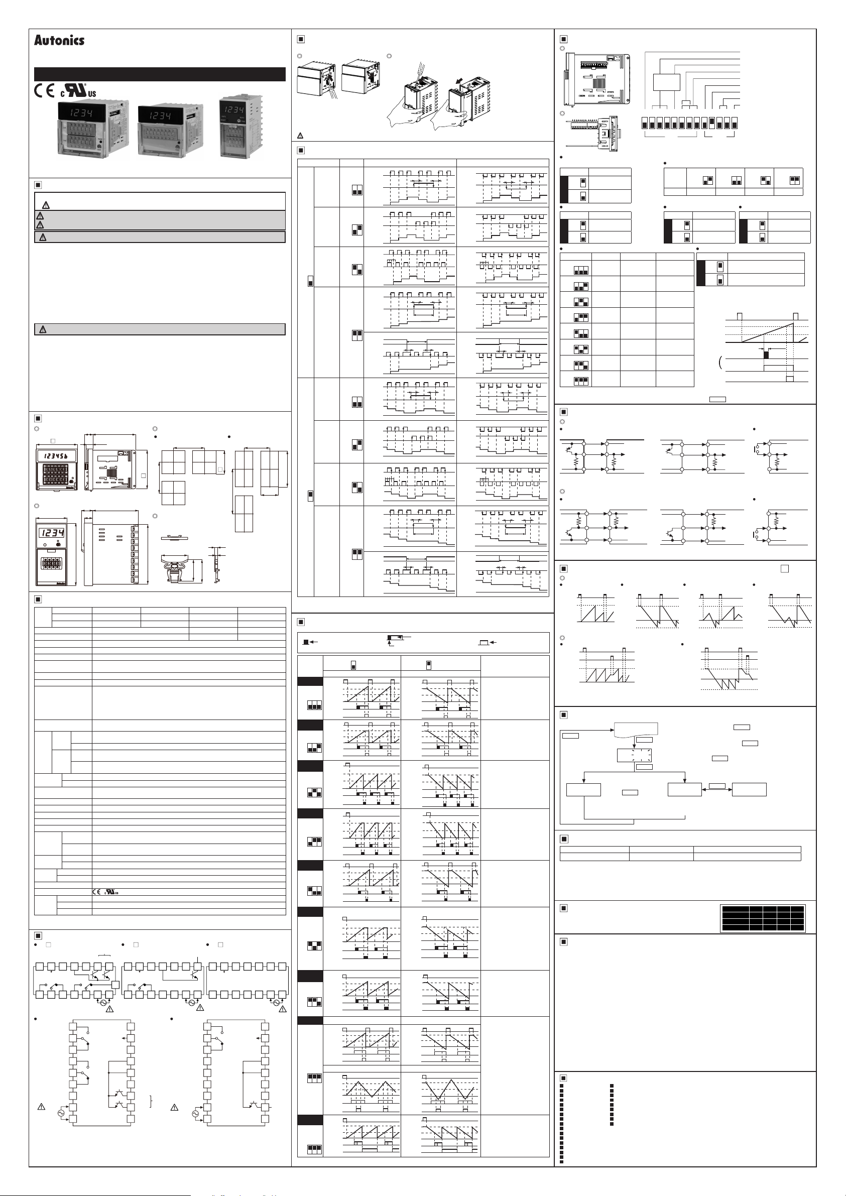
DRW161279AC
COUNTER / TIMER
FXM/FXH SERIES
I N S T R U C T I O N M A N U A L
Thank you for choosing our Autonics product.
Please read the following safety considerations before use.
Safety Considerations
Please observe all safety considerations for safe and proper product operation to avoid hazards.
※
※
symbol represents caution due to special circumstances in which hazards may occur.
Warning Failure to follow these instructions may result in serious injury or death.
Caution
Failure to follow these instructions may result in personal injury or product damage.
Warning
1. Fail-safe device must be installed when using the unit with machinery that may cause
serious injury or substantial economic loss. (e.g. nuclear power control, medical equipment,
ships, vehicles, railways, aircraft, combustion apparatus, safety equipment, crime/disaster
prevention devices, etc.)
Failure to follow this instruction may result in re, personal injury, or economic loss.
2. Install on a device panel to use.
Failure to follow this instruction may result in electric shock or re.
3. Do not connect, repair, or inspect the unit while connected to a power source.
Failure to follow this instruction may result in electric shock or re.
4. Check ‘Connections’ before wiring.
Failure to follow this instruction may result in re.
5. Do not disassemble or modify the unit.
Failure to follow this instruction may result in electric shock or re.
Caution
1. When connecting the power/sensor input and relay output, use AWG 20(0.50mm2) cable or
over, and tighten the terminal screw with a tightening torque of 0.74 to 0.90N.m.
Failure to follow this instruction may result in re or malfunction due to contact failure.
2. Use the unit within the rated specications.
Failure to follow this instruction may result in re or product damage.
3. Use dry cloth to clean the unit, and do not use water or organic solvent.
Failure to follow this instruction may result in electric shock or re.
4. Do not use the unit in the place where ammable/explosive/corrosive gas, humidity, direct
sunlight, radiant heat, vibration, impact, or salinity may be present.
Failure to follow this instruction may result in re or explosion.
5. Keep metal chip, dust, and wire residue from owing into the unit.
Failure to follow this instruction may result in re or product damage.
Dimensions
FXM Series
72
FXH Series
48 13
75
14 3
11.8
17.6
70
96
Panel cut-out
FXM Series FXH Series
Min. 90
0
+0.7
67.5
68
Min. 90
Bracket
( FXM, FXH Series
universal)
46
91 5
37.5
5
4
40 5
Specications
1-stage setting FX4H-1P4 FX4M-1P4 FX6M-1P4 FX8M-1P4
Model
2-stage setting FX4H-2P4 FX4M-2P4 FX6M-2P4
Indicator
Display digit 4-digit 6-digit 8-digit
Character size (W×H) 6×10mm 4×8mm 3.8×7.6mm
Power supply 100-240VACᜠ 50/60Hz
Permissible voltage range
Power consumption ● 1-stage: max. 4 6VA ● 2-stage: max. 5.8VA ● Indicator: max. 3.8VA
Max. counting speed
of CP1/CP2
Return time Max. 500ms
Min. signal width INH BIT, RESET: approx. 20ms
Input method
One-shot output time
Contact
Control
output
Solid
state
Mechanical Min. 10
Relay
life cycle
Electrical Min. 100,000 operations (250VAC 3A resistive load)
Repeat/Set/Voltage/
Temp. error
Insulation resistance Over 100MΩ (at 500VDC megger)
External power supply Max. 12VDCᜡ ±10% 50mA
Memory retention Approx. 10 years (non-volatile memory)
Dielectric strength 2,000VAC 50/60Hz for 1 min (between all terminals and case)
Noise immunity ±2kV the square wave noise (pulse width 1㎲) by noise simulator
Mechanical
Vibration
Malfunction
Mechanical 300m/s
Shock
Malfunction 100m/s
Ambient temp.
Environment
Ambient humi.
Protection structure IP20 (front part, EC standard)
Approval
1-stage setting
※
1
Weight
2-stage setting
Indicator Approx. 225g (approx. 160g)
※
1:
The weight includes packaging. The weight in parenthesis is for unit only.
※
Environment resistance is rated at no freezing or condensation.
Connections
FX M-2P4
12VDC
CP1
CP2
50mA
9
10
※
(INHIBIT)
OUT2
1
3
2
CONTACT
250VAC 3A, 30VDC 3A
RESISTIVE LOAD
FX4H-2P4
CONTACT
250VAC 3A,
30VDC 3A
RESISTIVE
LOAD
CONTACT
250VAC 3A,
30VDC 3A
RESISTIVE
LOAD
SOURCE
100-240VAC
50/60Hz 5.8VA
※
NHIBIT: In case of timer mode, this terminal is for time hold.
(voltage input (PNP): connect with 12VDC, non-voltage input (NPN): connect with 0VDC)
※
The above specications are subject to change and some models may be discontinued
without notice.
Be sure to follow cautions written in the instruction manual and the technical desctriptions
※
(catalog, homepage)
-
FX4M-I4 FX6M-I4 FX8M-I4
90 to 110% of rated voltage
Selectable 1cps/30cps/2kcps/5kcps (DIP switch)
Selectable voltage input (PNP) method or no-voltage input (NPN) method
[Voltage input (PNP) method]-input impedance: max. 10.8kΩ,
[H]: 5-30VDCᜡ, [L]: 0-2VDC
[No-voltage input (NPN) method]-short-circuit impedance: max. 470Ω ,
open-circuit impedance: min. 100kΩ
● 1-stage: 0.05 to 5 sec
● 2-stage: 1st setting 0.5 sec xed, 2nd setting 0.05 to 5 sec
● 1-stage: Instantaneuos SPDT (1c)
Type
● 2-stage: OUT1-Instantaneuos SPDT (1c) OUT2-Instantaneuos SPDT (1c)
Capacity
250VACᜠ 3A, 30VDCᜡ 3A resistive load
●1-stage: 1 NPN open collector
Type
●2-stage: OUT1-1 NPN open collector, OUT2-1 NPN open collector
●Load voltage: max. 30VDCᜡ
Capacity
●Load current: max. 100mA ●Residual voltage: max. 1VDC
000 000 operations
short-circuit residual voltage: max. 1VDC,
Max. ±0 01% ±0 05 sec
0.75mm amplitude at frequency 10 to 55Hz (for 1 min) in each X, Y, Z direction
for 1 hour
0.5mm amplitude at frequency 10 to 55Hz (for 1 min) in each X, Y, Z direction
for 10 minutes
2
(approx. 30G) in each X, Y, Z direction for 3 times
2
(approx. 10G) in each X Y Z direction for 3 times
-10 to 55℃, storage: -25 to 65
35 to 85%RH, storage: 35 to 85%RH
Approx. 245g (approx. 180g)
Approx. 265g (approx. 200g)
FX M-1P4
13
6
(INHIBIT)
14
17
7
※
CP1
※
1
CONTACT
250VAC 3A, 30VDC 3A
RESISTIVE LOAD
10
11
12
13
14
15
16
17
SOLID STATE OUT
30VDC 100mA
0VDC OUT1
RESET OUT2
128
11
OUT1
4
5
SOURCE
100-240VAC
50/60Hz 5.8VA
1
OUT2
2
3
4
OUT1
5
6
7
8
9 18
CP2
(INHIBIT)
OUT
CP1
CP2
12VDC
50mA
0VDC
0VDC
RESET
OUT1
OUT2
9
2
12VDC
50mA
10
3
℃
SOLID STATE OUT
30VDC 100mA
0VDC
RESET
11
128
5
4
SOURCE
100-240VAC
50/60Hz 4.6VA
FX4H-1P4
CONTACT
250VAC 3A,
30VDC 3A
RESISTIVE
LOAD
SOLID
STATE
OUT:
30VDC
100mA
SOURCE
100-240VAC
50/60Hz 4.6VA
FX M-I4
CP1
13
14
※
7
6
1
1
2
3
4
5
6
7 16
8 17
9 18
CP2
9
(INHIBIT)
2
OUT
Min. 115
-
ᜡ
12VDC
50mA
10
3
(INHIBIT)
0VDC
※
(unit: mm)
Min. 65
+0.6
45
RESET
128
13
11
6
4
5
SOURCE
100-240VAC
50/60Hz 3.8VA
10
11
12
13
14
15
CP1
CP2
12VDC
50mA
0VDC
0VDC
RESET
Detaching Case or DIP Switch Cover
※
Turn OFF the power before detaching the case or DIP switch cover.
FXM Series FXH Series
Push and pull the groove of DIP
switch cover with a flat head driver
to the front. The cover is detached
from the case.
Push the groove of the front guide with a flat
①
head driver and pull it to the front.
Be sure not to be wounded when using a tool.
Input Operation Mode (Counter)
Input mode SW1 Voltage input (PNP) method No-voltage input (NPN) method
Up/
Down-A
ON
(command
OFF
input)
Up/
Down-B
ON
(individual
OFF
input)
Up/
Down-C
Up
mode
4
ON
OFF
0
+0.8
92
Down
mode
0
4
ON
OFF
※
A: over min. signal width, B: over than 1/2 of min. signal width.
If the signal is smaller than these width, it may cause counting error (±1).
(phase
difference
input)
Up
(adding
input)
Up/
Down-D
(command
input)
Up/
Down-E
(individual
input)
Up/
Down-F
(phase
difference
input)
Down
(
subtracting
input)
ON
OFF
ON
OFF
ON
OFF
ON
OFF
ON
OFF
ON
OFF
H
CP1
L
3 2
H
CP2
L
Count
H
CP1
L
3 2
H
CP2
L
Count
H
CP1
L
3 2
H
CP2
L
Count
H
CP1
L
H
CP2
L
Count
3 2
H
CP1
L
H
CP2
L
Count
H
CP1
L
3 2
H
CP2
L
n
Count
0
H
CP1
L
3 2
H
CP2
L
n
Count
0
H
CP1
L
3 2
H
CP2
L
Count
0
H
CP1
L
H
CP2
L
Count
3 2
0
H
CP1
L
H
CP2
L
Count
0
0
0
0
0
BBBB
n
n
n
BBBB
0
1
1
1
1
1
n-1
n-2
n-1
n-2
n-1
n-1
n-1
A
3
2
2
3
2
2
1
23212
A A
No counting
3
2
No counting
A A
2
A
n-1
n-2
n-3
n-1 n-1
n-2
n-1
n-2
n-2
n-3
A A
No counting
n-2
n-3
No coun ing
A A
n-2
A
2
1
2
1
4
4
3
A
n-2
n-2
n-2
n-4
n-3
n-4
H
CP1
L
H
CP2
L
3
Count
0
H
CP1
L
H
CP2
L
3
Count
0
H
CP1
L
H
CP2
L
3
Count
H
CP1
L
H
CP2
L
5
Count
0
H
CP1
L
H
CP2
L
5
Count
0
H
CP1
L
H
CP2
L
n
Count
n-3
0
H
CP1
L
H
CP2
L
n
Count
n-3n-3
0
H
CP1
L
H
CP2
L
Count
n-3
0
H
CP1
L
H
CP2
L
n
Count
n-5
0
H
CP1
L
H
CP2
L
n
Count
n-5
0
Output Operation Mode
Self-holding output
One-shot output of OUT1
(0.5 sec xed)
OFF
RESET
2nd setting
1st setting
OUT1
OUT2
(OUT)
RESET
2nd setting
1st setting
OUT1
OUT2
(OUT)
RESET
2nd setting
1st setting
OUT1
OUT2
(OUT)
RESET
2nd setting
1st setting
OUT1
OUT2
(OUT)
RESET
2nd setting
1st setting
OUT1
OUT2
(OUT)
RESET
2nd setting
1st setting
OUT1
OUT2
(OUT)
RESET
2nd setting
1st setting
OUT1
OUT2
(OUT)
RESET
2nd setting
1st setting
OUT1
OUT2
(OUT)
RESET
2nd setting
1st setting
OUT1
OUT2
(OUT)
RESET
2nd setting
1st setting
OUT1
OUT2
(OUT)
4
ON
Down mode
0
0
0
0
0
0
0
0
0
0
14
7
SOLID
STATE
OUT:
30VDC
100mA
One-shot output of OUT2
(0.05 to 5 sec)
Output
mode
(SW1)
F
7 6 5
ON
OFF
N
7 6 5
ON
OFF
C
7 6 5
ON
OFF
R
7 6 5
ON
OFF
K
7 6 5
ON
OFF
P
7 6 5
ON
OFF
Q
7 6 5
ON
OFF
S
Counter
mode
7 6 5
ON
OFF
S
Timer
mode
7 6 5
ON
OFF
※
Set one-shot output time by front TIME volume switch.
4
ON
Up mode
OFF
Up, Up/Down-A, B, C Down, Up/Down-D, E, F
RESET
2nd setting
1st setting
0
OUT1
OUT2
(OUT)
RESET
2nd setting
1st setting
0
OUT1
OUT2
(OUT)
RESET
2nd se ting
1st se ting
0
OUT1
OUT2
(OUT)
RESET
2nd setting
1st setting
0
OUT1
OUT2
(OUT)
RESET
2nd set ing
1st setting
0
OUT1
OUT2
(OUT)
RESET
2nd setting
1st setting
0
OUT1
OUT2
(OUT)
RESET
2nd setting
1st setting
0
OUT1
OUT2
(OUT)
Up Down
RESET
2nd setting
1st setting
0
OUT1
OUT2
(OUT)
Up/Down-A, B, C Up/Down-D, E, F
RESET
2nd setting
1st setting
0
OUT1
OUT2
(OUT)
RESET
2nd se ting
1st se ting
0
OUT1
OUT2
(OUT)
Pull the front guide to
②
the front.
The case is detached.
※
CP: Clock Pulse
A
A
3
212
2
1
BB
0
BBBB
n
232
1
BB
2
1
2
1
No counting
A A
1
n-1
n-2
n-3
n-1
n-2
n-3
n-1
n-2
n-3
n-1
n-2
No counting
A
n-1
3
212
A A
No counting
3
2
A A
n-2
n-1
n-2
n-2
A A
No counting
n-3
n-2
2
1
1
4
4
3
n-1
n-2
n-1
n-2
n-1
n-2
n-4
A
n-3
n-4
Self-holding output
Operation
After count-up, counting display
value increases or decreases
until reset signal input is applied
and self-holding output is
maintained.
After count-up, counting display
value and self-holding output
are maintained until reset signal
input is applied.
When count-up, counting display
value is reset and it counts
simultaneously.
Self-holding output of OUT1
turns OFF after one-shot output
time of OUT2.
One-shot output time of OUT1 is
regardless of OUT2 output.
After count-up, counting display
value is reset after one-shot
output time of OUT2 and it
counts simultaneously. Selfholding output of OUT1 turns
OFF after one-shot output time
of OUT2.
One-shot output time of OUT1 is
regardless of OUT2 output.
After count-up, counting display
value increases or decreases
until reset signal input is applied.
Self-holding output of OUT1
turns OFF after one-shot output
time of OUT2.
One-shot output time of OUT1 is
regardless of OUT2 output.
After count-up, counting display
value is maintained while OUT2
output is ON. Counting value
is internally reset and it counts
simultaneously. When OUT2
output is OFF, displays counting
value while OUT2 output is ON,
and it increases or decreases.
Self-holding output of OUT1
turns OFF after one-shot output
time of OUT2.
After count-up, counting display
value increases or decreases
during one-shot time of OUT2.
Self-holding output of OUT1
turns OFF after one-shot output
time of OUT2.
One-shot output time of OUT1 is
regardless of OUT2 output.
● Up, Up/Down-A, B, C input mode
: OUT1 output maintains ON
when counting display value
is larger or equal than 1st
setting value.
: OUT2 output maintains ON
when counting display value
is larger or equal than 2nd
setting value.
● Down, Up/Down-D, E, F input mode
: OUT1 output maintains ON
when counting display value
is smaller or equal than 1st
setting value.
: OUT2 output maintains ON
when counting display value
is smaller or equal than 2nd
setting value.
OUT1 and OUT2 turns
OFF → ON → OFF repeatedly
(icker).
DIP Switch Setting
FXM Series
ON
Counter/
Timer
※
※
2
1
FXH Series
Input logic
(CP1, CP2, INHIBIT, RESET input)
SW2 Function
1
3
Counter/Timer mode
SW2 Function
3
4
SW1 4-digit 6-digit 8-digit
ON
3
OFF
ON
OFF
ON
OFF
5
ON
OFF
ON
OFF
ON
OFF
5
ON
OFF
ON
OFF
※
How to change settings
Power OFF → change settings → power ON → press
n-3
Voltage input (PNP)
Solid state input (standard sensor: PNP output type sensor) Contact input
Sensor
n-3
ON
NPN
ON
OFF
(no-voltage input)
PNP
ON
OFF
(voltage input)
ON
Counter mode
OFF
ON
Timer mode
OFF
3 2 1
99.99sec 99999.9sec 999999.99sec
3 2 1
999.9sec 999999sec 9999999.9sec
3 2 1
9999sec
3 2 1
99min
59sec
3 2 1
999.9min 99999.9min 9999999.9min
3 2 1
99hour
59min
3 2 1
999.9hour
3 2 1
9999hour 99999.9hour
Input Connection
Counter/Timer
Brown
※
Black
Blue
(PNP output)
※
CP1, CP2 ( NHIBIT), RESET input part
No-voltage input (NPN)
n-3
Solid state input (standard sensor: NPN output type sensor) Contact input
Sensor
n-5
(NPN output)
※
CP1, CP2 ( NHIBIT), RESET input part
Counting & Time Operation for Indicator (FX M-I4)
Counting operation
Input mode Up
n-5
RESET
+ Max.
display
value
0
Time operation
Up mode
RESET
INHIBIT
+ Max.
display
value
0
※
- display is only for F, K, Q, S output operation mode and it cannot be set.
Brown
Black
Blue
Counter/Timer
※
8 7 6 5 4 3 2 1 5 4 3 2 1
ON
OFF
SW1
※
1: Only 2-stage setting model has no. 8 of SW1.
※
2: Indicator model does not have no. 5, 6, 7, 8 of SW1.
Max. counting speed (counter)
ON
SW2
OFF
Function 1cps 30cps 2kcps 5kcps
Memory backup
SW2 Function
ON
No memory backup
OFF
5
ON
Memory backup
OFF
99min
59.99sec
999min
59.9sec
99hour 59min
59sec
9999hour
59min
+12V
Inner
circuit
10 8kΩ
0V
5.4kΩ
Input mode Down Input mode
RESET
+ Max.
display
value
- Max.
display
value
+12V
Inner
circuit
0V
0
99999999sec
99999min
59.9sec
999hour 59min
59.9sec
9999hour
59min 59sec
99999hour
59.9min
Sensor
Brown
Black
Blue
(PNP open collector output)
Sensor
Brown
Black
Blue
(NPN open collector output)
Up/Down-A, B, C
RESET
+ Max.
display
value
0
- Max.
display
value
Down mode
RESET
INHIBIT
+ Max.
display
value
- Max.
display
value
3 2
One-shot output of OUT1 Time range (timer)
SW1 Function
ON
OFF
8
ON
OFF
※
This function is for setting one-shot output
(0.5 sec fixed) or self-holding output (until OUT2
turns OFF) of OUT1 at 2-stage setting model.
※
Example of output operation mode F
RESET
2nd setting
1st setting
OUT1
Counter/Timer
※
Counter/Timer
※
0
One-shot of OUT1
Output operation mode
Up/Down mode
Input operation mode (Counter)
Time range (Timer)
Memory backup
Counter/Timer mode
Max. counting speed (Counter)
Input logic (NPN/PNP)
Factory default
SW2
3 2
ON
OFF
ON
OFF
Up/Down mode
SW1 Function
ON
OFF
4
ON
OFF
One-shot output of OUT1
Self-holding output of OUT1
One-shot output
Self-holding
output
Self-holding
OUT2
output
(OUT)
RESET
key or input signal (min. 20ms)
10 8kΩ
5.4kΩ
+12V
Inner
circuit
0V
+12V
Inner
circuit
※
※
Counting speed
: Set as 1 or 30cps
※
0V
※
Counting speed
: Set as 1 or 30cps
Input mode
Up/Down-D, E, F
RESET
+ Max.
display
value
- Max.
display
value
Dot for Decimal Point / Hour. Min. Second
RESET
3 sec
Setting mode
RUN mode
RESET
DP
RESET
3 sec
Counter mode Timer mode
Set decimal point
RESET
by front
Hour, Min, Sec are not
divided with dot.
E g.)
5959
※
In run mode, hold the
and it enters setting mode [DP].
※
In setting mode, hold the
and it saves the setting and returns to RUN mode.
※
If there is no
setting mode, it returns to RUN mode.
CLR SET
: 59 min 59 sec
RESET
key for over 3 sec,
RESET
key for over 3 sec,
RESET
key input for 60 sec when entering
RESET
Hour, Min, Sec are divided with
dot.
E.g.)
)5(59
Error Display and Output Operation
Error Display Error description Troubleshooting
ERR0
※
When error occurs, the output turns OFF.
※
When1stsettingvalueissetas0(zero),OUT1maintainsOFF.
When2ndsettingvalueissmallerthan1stsettingvalue,1stsettingvalueisignoredandonly
OUT2outputoperates.
※
Indicator model does not have error display function.
Unit Sticker
Unit sticker is included.
Use the sticker for your application.
Cautions during Use
1. Follow instructions in ‘Cautions during Use’. Otherwise, It may cause unexpected accidents.
2. Use the product, 0.1 sec after supplying power.
3. When supplying or turning off the power, use a switch or etc. to avoid chattering.
4. Install a power switch or circuit breaker in the easily accessible place for supplying or
disconnecting the power.
5. In case of contact input, set count speed to low speed mode (1cps or 30cps) to operate.
If set to high speed mode (2kcps or 5kcps), counting error occurs due to chattering.
6. Keep away from high voltage lines or power lines to prevent inductive noise.
In case installing power line and input signal line closely, use line lter or varistor at power
line and shielded wire at input signal line.
Do not use near the equipment which generates strong magnetic force or high frequency
noise.
7. This product may be used in the following environments.
Indoors (in the environment condition rated in ‘Specications’)
①
Altitude max. 2,000m
②
Pollution degree 2
③
Installation category II
④
Major Products
Photoelectric Sensors Temperature Controllers
Fiber Optic Sensors Temperature/Humidity Transducers
Door Sensors SSR/Power Controllers
Door Side Sensors Counters
Area Sensors Timers
Proximity Sensors Panel Meters
Pressure Sensors Tachometer/Pulse (Rate) Meters
Rotary Encoders Display Units
Connector/Sockets Sensor Controllers
Switching Mode Power Supplies
Control Switches/Lamps/Buzzers
I/O Terminal Blocks & Cables
Stepper Motors/Drivers/Motion Controllers
Graphic/Logic Panels
Field Network Devices
Laser Marking System (Fiber, Co₂, Nd: YAG)
Laser Welding/Cutting System
Setting value is 0. Change the setting value anything but 0.
※
Indicator model does not have error display function.
COUNTER mm inch mm inch
TIMER m hour m hour
COUNTER sec cm sec cm
TIMER min yd min yd
3 2
3 2
ON
OFF
Down mode
Up mode
0.5 sec
Counter/Timer
+12V
Inner
circuit
10.8kΩ
0V
Counter/Timer
+12V
5.4kΩ
Inner
circuit
0V
0
: 59 min 59 sec
DRW161279AC
 Loading...