

AEP-E-0180C
LCD Touchscreen Paperless Recorder
KRN1000 SERIES
I N S T R U C T I O N M A N U A L
Please read the following safety considerations before use.
Safety Considerations
※
Please observe all safety considerations for safe and proper product operation to avoid hazards.
※
Safety considerations are categorized as follows.
Warning
Caution
※
The symbols used on the product and instruction manual represent the following
symbol represents caution due to special circumstances in which hazards may occur.
Failure to follow these instructions may result in serious injury or death.
Failure to follow these instructions may result in personal injury or product damage.
Warning
1. Fail-safe device must be installed when using the unit with machinery that may cause serious injury or substantial economic
loss. (e.g. nuclear power control, medical equipment, ships, vehicles, railways, aircraft, combustion apparatus, safety
equipment, crime/disaster prevention devices, etc.)
Failure to follow this instruction may result in personal injury, re, or economic loss.
2. The unit must be installed on a device panel before use.
Failure to follow this instruction may result in electric shock.
3. Do not connect, repair, or inspect the unit while connected to a power source.
Failure to follow this instruction may result in electric shock .
4. Do not disassemble or modify the unit. Please contact us if necessary.
Failure to follow this instruction may result in electric shock or re.
5. Check the terminal numbers before connecting the power source.
Failure to follow this instruction may result in re or burning the unit.
Caution
1. Do not use the unit outdoors.
Failure to follow this instruction may result in shortening the life cycle of the unit, or electric shock.
2. Use the unit within the rated specications.
Failure to follow this instruction may result in shortening the life cycle of the unit, or re.
3. Do not use water or oil-based detergent when cleaning the unit. Use dry cloth to clean the unit.
Failure to follow this instruction may result in electric shock or re.
4. Do not use the unit where ammable or explosive gas, humidity, direct sunlight, radiant heat, vibration, or impact may be
present.
Failure to follow this instruction may result in re or explosion.
5. Keep dust and wire residue from owing into the unit.
Failure to follow this instruction may result in re or product damage.
6. Check the polarity of the power contact before wiring the unit.
Failure to follow this instruction may result in re or explosion.
※
Please read “Safety Considerations” in KRN1000 user manual before using.
Ordering Information
KRN1000 04 0 1 0 S
Input channels
Item
User Manual
For the detail information and instructions, please refer to user manual and user manual for communication.
Download manuals from the enclosed CD-ROM or our web site (www.autonics.com).
※
The above specications are subject to change and some models may be discontinued without notice.
Thank you for choosing our Autonics product.
Case
Power supply
Communication output
Option input/output
S Standard panel installation type
0 100-240VAC 50/60Hz
1 RS422/485+Ethernet+USB Device
0 None
1 Alarm relay output 8 channels
2 Alarm relay output 6 channels + Digital input 2 channels
3
4
04 4 channels
08 8 channels
12 12 channels
16 16 channels
KRN1000 Paperless recorder
Alarm r elay outp ut 6 chann els
+ 24VDC pow er output for transmitte r
Alarm relay output 4 channels + Digital input 2 channels
+ 24VDC pow er output for transmitte r
Specications
Series KRN1000
Power supply 100-240VAC 50/60Hz
Allowable voltage range 85 to 110% of rated voltage
Power consumption Max. 23VA
Display method 5.6 inch TFT Color LCD
Resolution 640×480 pixels
Screen
Adjusting brightness 3-level (Min/Standard/Max)
Input method Touch screen (Pressure sensitive type)
Number of input channels 4 / 8 / 12 / 16 channels
Universal input
Sampling period
Recording period 1 to 3600 sec
Internal memory Approx. 200MB
External memory SD / USB memory max. 32GB
Dielectric strength
Vibration
Insulation resistance Over 20MΩ (at 500VDC megger)
Noise immunity Square shaped noise by noise simulator (pulse width 1µs) ±2kV
Time accuracy Within ±2 min/year (available up to 2099)
Protection structure IP50 (front part)
Environment
Approval
Weight
※
1: For more information of universal input, refer to ‘
※
2: The weight includes packaing. The weight in parenthesis is for unit only.
※
Environment resistance is rated at no freezing or condensation.
※
1
Mechanical 10 to 60Hz 4.9m/s
Malfunction 10 to 60Hz 1m/s
Ambient temperature 0 to 50℃, storage: -20 to 60℃
Ambient humidity 35 to 85%RH, storage: 35 to 85%RH
※
2
Temperature sensors (thermocouple, RTD), Analog (voltage, current (shunt))
1 to 4-CH: 25ms/125ms/250ms, 5 to 16-CH: 125ms/250ms
(internal sampling period is average movement lter and alarm output operation unit time)
2300VAC 50/60Hz for 1 min (between power terminals and case)
※
Except ethernet and USB device
Approx. 1290 to 1400g (approx. 590 to 700g)
2
in each X, Y, Z direction for 1 hour
2
in each X, Y, Z direction for 10 min
Input/Output’.
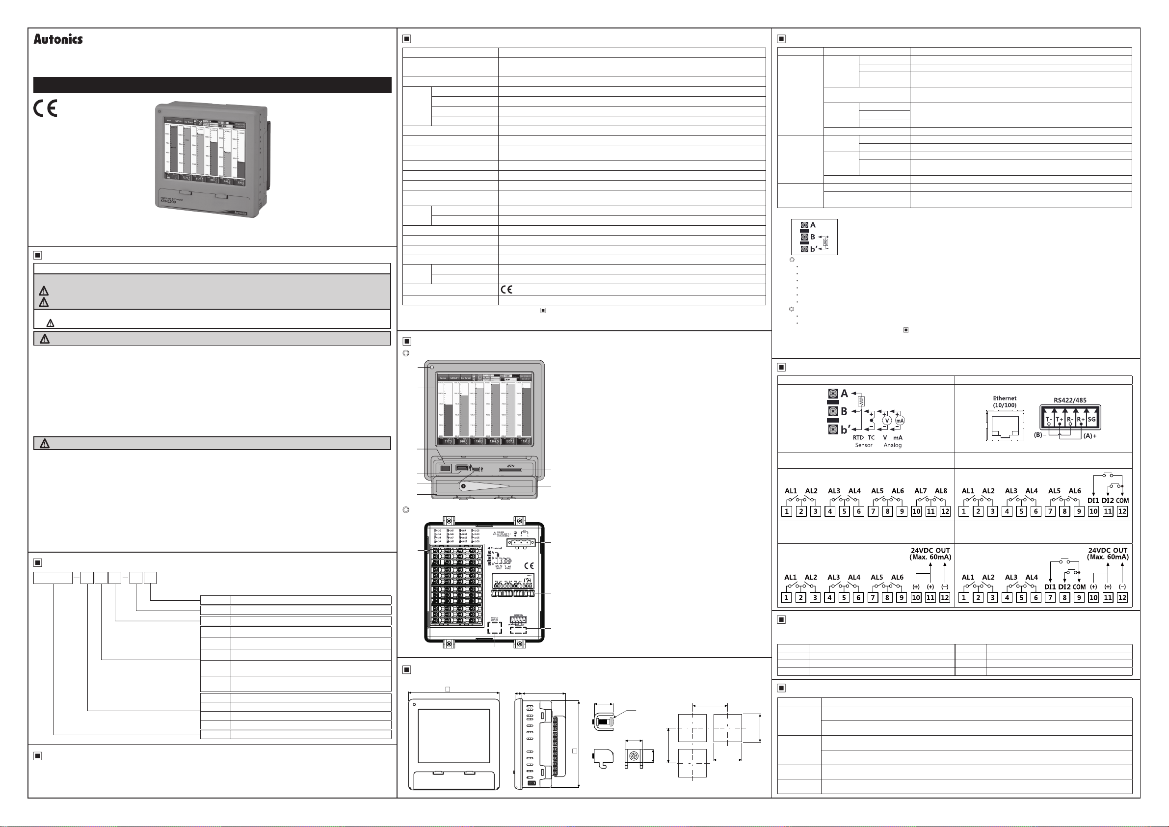
Unit Description
Front part
1
2
4
5
6
3
Rear part
1
2
1. Power indicator: Power tur ns ON and th e red LED turns ON.
2. Screen: Measrue d value is di splayed as trand graph, bar bar graph,
3. Front cover: Open th e front cover. There are p ower swit ch and, US B
4. Power s witch: Turn O N/OFF t he power of K RN1000.
5. USB ho st por t: Connect the US B memor y.
6. USB device po rt: Used for parameter settings.
7. SD card slot: SD card memor y slot. It s uppor ts up to 32G B.
8. Sty lus pen: Used for touching screen.
※
digital gures.
Host /Devic e, SD car d slot.
It reco gnizes up t o 32GB. Wh en using ex tensio n cable,
cable l ength sh ould be up to 1.5m.
Do not co nnect th e other US B device s except US B memor y at USB ho st
port.
7
8
1. Sensor input t ermin al: Connects universal input.
2. Ethernet port: Connector for ether net cab le.
5
3. RS42 2/485 port :
4. Option input/output port: Connects for option input/output (digital
5. Power i nput: Power conn ection (100-240VAC 5 0/60 Hz)
It communicate s Modbus TCP.
Connects RS42 2/48 5 for Modbus RTU co mmunic ation.
input (non -co ntact / contact), alar m output,
power for transmitter).
4
3
Dimensions
144
11.5
69.2
137.5
● Bracket
15
M4
14
10.4
● Panel cut-out
Min. 175
Min. 175
138
+1.0
0
(unit: mm)
+1.0
0
138
Input/Output
Type Input/Output type Description
Input type
Universal input
Option
input/output
Communication
※
output
※
1: Current measurement and connection examples
※
2:
At room temperature (23℃ ± 5℃)
Out of room temperature range
※
3: Input/Output is different by option. Refer to ‘
※
4: For supplying power for transmitter, it is recommened to use shield cable to reduce noise.
※
5: RS422/485, ethernet, USB device communication outputs are not used at the same time.
※
If sensor input line is longer, it is recommended to use shield cable to reduce noise.
Input impedance
Display
accuracy
Resolution 16-bit
Digital
input
Alarm relay
※
3
output
Power output for transmitter
RS422/485 Modbus RTU ※It is recommended to use shielded cable over AWG 24.
Ethernet IEEE802.3 10 BASE-T / IEEE802.3U 100 BASE-TX (Modbus TCP)
5
USB Device USB V2.0 Full Speed (Modbus RTU)
RTD Cu50Ω (-200≤T≤200): (±0.1% F.S. or ±1.5℃, select the higher one) ±1-digit
RTD DPt50Ω (-200≤T≤500): (±0.1% F.S. or ±1.5℃, select the higher one) ±1-digit
Thermocouple R, S, C, G type (0≤T≤100): (±0.1% F.S. or ±4.0℃, select the higher one) ±1-digit
Thermocouple U, T type (-100≤T≤400): (±0.1% F.S. or ±2.0℃, select the higher one) ±1 digit
Thermocouple B type, below 400℃: There is no accuracy standards.
All thermocouples, below -100℃: (±0.3% F.S. or ±4.0℃, select the higher one) ±1-digit
RTD Cu50Ω (-200≤T≤200): (±0.2% F.S. or ±3.0℃, select the higher one) ±1-digit
RTD DPt50Ω (-200≤T≤500): (±0.2% F.S. or ±3.0℃, select the higher one) ±1-digit
RTD JPt100Ω, DPt100Ω, DPt50Ω, Cu100Ω, Cu50Ω (supplied current: approx. 190µA)
Thermocouple B, C (W5), E, G, J, K, L, L (Russia), N, P, R, S, T, U
Analog
RTD
Thermocouple
※
2
Analog
No-contact input ON: Residual voltage max. 1V, OFF: Leakage current max. 0.1mA
Contact input ON: Max. 1kΩ, OFF: Min. 100kΩ, Short-circuit: Approx. 4mA
Capacity 250VAC 3A, 30VDC 3A, 1 Form A (resistive load)
Life cycle
Connect 250Ω shunt resistance and set analog input type 0-20mA (shunt) / 4-20mA (shunt).
It is available to measure 0-20mA / 4-20mA current.
Voltage: ±60mV, ±200mV, ±2V, 1-5V, ±5V, -1V-10V
Current: 0-20mA, 4-20mA (measureable when using 250Ω shunt resistance)
Voltage (V): Approx. 205kΩ
RTD, Thermocouple, Voltage (mV): Min. 200kΩ
Warm-up time: Max. 30 min
At room temperature (25±5℃): ±0.1% F.S.±1-digit
Out of room temperature: ±0.2% F.S.±1-digit
Mechanical: Min. 20,000,000 operations
Electrical: 100,000 operations (3A 250V AC, 3A 30V DC)
※
4
24±2VDC, Max. 60mA ※Built-in over current protection circuit
Ordering Information’.
Input/Output Circuit
Universal input Communication output
Option input/output 1
(alarm output 8 channels)
Option input/output 3
(alarm output 6 channels + power for transmitter output)
Option input/output 2
(alarm output 6 channels + digital input 2 channels)
Option input/output 4
(alarm output 4 channels + digital input 2 channels
+ power for transmitter output)
Comprehensive Device Management Program [DAQMaster]
DAQMaster is the comprehensive device management software for setting parameters and monitoring processes.
DAQMaster can be downloaded from our web site at www.autonics.com.
Item Minimum specications Item Minimum specications
System IBM PC compatible computer with Pentium Ⅲ or above Hard disk 1GB+ of available hard disk space
Operations
Memory 256MB+ Others RS232C serial port (9-pin), USB port
Windows 98/NT/XP/Vista/7/8/10 VGA Resolution: 1024×768 or higher
Error Message
Error message Descriptions
HHHH
LLLL
BURN
ASKey
When input type is temperature sensor (Thermocouple, RTD) and the measurement value is higher than high-limit value of input
range, it ashes HHHH. It is cleared when the measurement value is within the high-limit range.
When input type is analog (voltage, current (shunt)) and the measurement value is over 10% of high-limit input range, it ashes
HHHH. It is cleared when the measurement value is within 10% of high-limit input range.
When input type is temperature sensor (Thermocouple, RTD) and the measurement value is lower than low-limit value of input
range, it ashes LLLL. It is cleared when the measurement value is within the low-limit range.
When input type is analog (voltage, current (shunt)) and the measurement value is over 10% of low-limit input range, it ashes
LLLL. It is cleared when the measurement value is within 10% of low-limit input range.
When input type is temperature sensor (Thermocouple, RTD) and input is break, it ashes BURN.
It is cleared when input is connected.
When forgetting and entering unvaild password 3 times, “ASKey” appears with error message.
Contact our service center with ASKey.
※
1
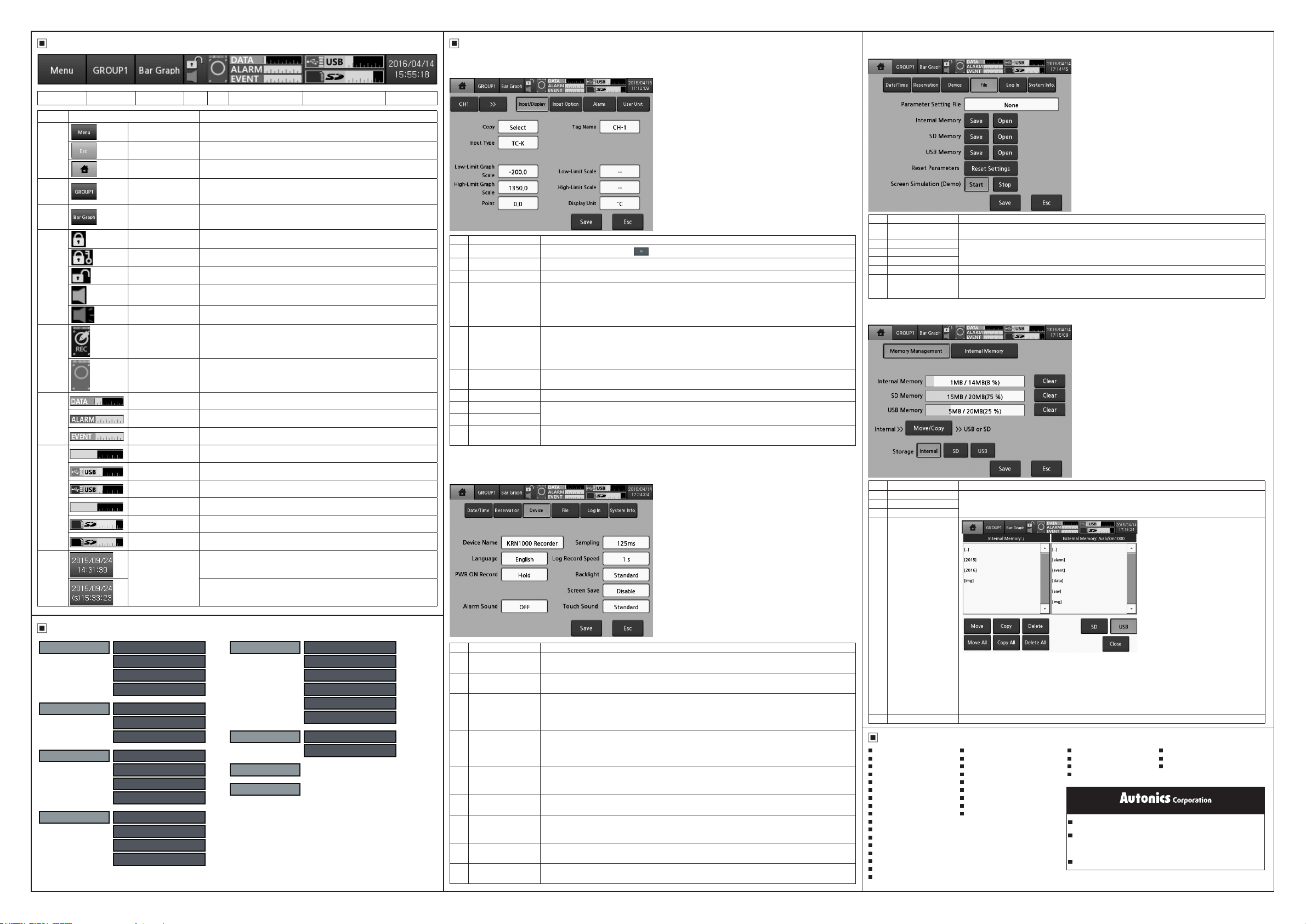
Status Display Part
Major Menu
1) Input/Display
It sets input type of each channel of KRN1000.
[Menu → Input CH Info. → Input/Display]
[Menu → System Info. → File]
3) File
It manages parameter setting files which are saved at KRN1000 memory, resets parameters.
1 2 3 4 5 6 7 8
Section Item Description
Menu Displays menu.
1
2
3
4
5
6
7
8
Esc Moves from menu to current screen.
Home Moves to main screen.
Group
Graph
Lock
Lock Setting
Unlock
No Alarm Displays at no alarm.
Alarm Displays when alarm occurs.
Internal Memory
Record
Internal Memory
No Record
Data Record Space Displays usage details of data recording space.
Alarm Record Space Displays empty space of alarm data memory.
Event Record Space Displays empty space of event data memory.
USB Memory
No Connection
USB Memory No Save
(gray)
USB Memory Save
(yellow)
SD Card
No Connection
SD Card No Save
(gray)
SD Card Save
(yellow)
Date/Time
Displays currently displayed group name.
Touch the icon and select the group. You can set the group name and the set
group name is displayed.
Select the displayed graph at the current screen.
Select one among bar graph, vertical/horizontal trend graph, divided vertical/
horizontal trend graph, vertical/horizontal mixed graph, digital group/all.
Displays at standard user mode.
(activated log-in function or log off status)
Displays at administor mode.
(activated log-in function and log-in as administor mode)
Displays at unlock.
(inactivated log-in function)
Displays when displaying measurement value and no recording it at internal
memory.
Displays usage details of data recording space.
Displays when USB memory is not connected.
Displays when internal memory data does not save at USB memory.
Displays when internal memory data saves at USB memory.
Displays when SD card is not connected.
Displays when internal memory data does not save at SD card.
Displays when internal memory data saves at SD card.
Displays date and time.
If summer time is set, "(s)" marks in front of time.
Menu
Display History
File History
Group Setting
Touch Calibration
Status Alarm List
Event List
AO/DI Status
Input CH Info. Input/Display
Input Option
Alarm
User Unit
Option Info.
※
For more information about menu, refer to KRN1000 user manual.
Alarm Output
Digital Input
RS422/485
Ethernet/USB
System Info. Date/Time
Reservation
Device
File
Log In
System Info.
Memory Info. Memory Management
Internal Memory
Screen Capture
Log OFF/Power OFF
1
2
7
3
4
5
6
No Item Descriptions
1 Channel Moves channel. Touch 'CH1' or
2 Copy Copies the other channels parameters of the same group. Select the channel to be copy.
3 Input Type Set the input type. Input types are total 27: thermocouple, RTD, voltage, current (shunt).
Low-Limit Graph Scale/
4
Low-Limit Input
High-Limit Graph Scale/
5
High-Limit Input
6 Point
7 Tag Name Set the channel name.
8 Low-Limit Scale
9 High-Limit Scale
10 Display Unit
2) Device
It sets initial setting and option of KRN1000.
[Menu → System Info. → Device]
8
9
10
to change the channel.
In case of temperature sensor input, set the low-limit graph scale value within the input range.
Setting range: Min. value of input range to high-limit graph scale value-F.S. 5%
E.g.) In case of TC-K input, -200.0 to 1350.0℃ of input range, and setting range is -200.0 to 1272.5℃.
(-F.S.=77.5)
In case of analog input, it displays low-limit input value.
In case of temperature sensor input, set the high-limit graph scale value within the input range.
Setting range: Low-limit graph scale value+F.S. 5% to Max. value of input range
E.g.) In case of TC-K input, -200.0 to 1350.0℃ of input range, and setting range is -122.5 to 1350℃.
(+F.S.=77.5)
In case of analog input, it displays high-limit input value.
- Temperature sensor input: 0, 0.0 (set the decimal point for the measurement value)
- Analog input: 0, 0.0, 0.00, 0.000, 0.0000 (set the decimal point position for the scale value)
Set the desired display value based on the measurement value.
It is activated only for analog (voltage, current (shunt)) input type.
- Temperature senosr input: Temperature units, ℃, ℉, ˚K are available.
- Analog input: 72 display units are available. When not using unit, select blank.
1 4
2
3
5
6
7
8 9
No Item Descriptions
1 Device Name
2 Language
3 PWR ON Record
4 Sampling
Log Record
5
Speed
6 Backlight
7 Screen Save
8 Alarm Sound
9 Touch Sound
Set KRN1000 device name.
It supports English capital/small letter, sign and number up to 16 characters.
Set KRN1000 display langauge.
It supports Korean, English and Chinese.
Set record status when supplying power or re-supplying power at power failure.
- Hold: It maintains record status (recording/stop) of before power OFF.
- Record: It records when power is ON.
- Stop: It does not record regardless when power is ON.
Set internal sampling period of measurement value.
Setting range(varied by number of input channel connections)
- Below 4CHs: 25, 125, 250ms
- The others: 125, 250ms
Set log speed for recording measurement value at system memory.
Setting range: 1 to 3600 sec
E.g.) When setting as 3 sec, it records present value and the value after 3 sec.
Set display backlight level.
Setting range: Min., Standard, Max.
For saving LCD life cycle and power, screen can automatically turn OFF.
Even though during screen save status, it maintains recording. Touch the screen and it turn ON the screen.
Setting range: 0 to 360 min (0: disable screen save)
Set alarm sound volume.
Setting range: OFF, Min., Standard, Max.
Set touch sound volume when toucing the menu or button of screen.
Setting range: OFF, Min., Standard, Max.
1
2
3
4
5
6
No Item Descriptions
Parameter
1
Setting File
2 Internal Memory
3 SD Memory
4 USB Memory
5 Reset Parameters Reset parameter settings as factory default.
Screen Simulation
6
(Demo)
Displays parameter setting le name.
Save the set parameter information at the dedicated memory or open it.
Execute simulation the set parameters.
Touch ‘Start’ and re-boot the unit and simulation mode starts.
Touch ‘Stop’ to exit simulation mode and re-boot the unit.
4) Memory Management [Menu → Memory Info. → Memory Management]
It manages internal/external memory. You can check memory usage and move and copy data files.
1
2
3
4
5
Item Descriptions
No
1 Internal Memory
2 SD Memory
3 USB Memory
4 Move/Copy
5 Storage Select the memory to save the data.
Displays each memory usage.
Touch ‘Clear’ to initial the memory.
Moves/Copies les of internal memory to SD/USB memory.
- Move: Moves the le to external memory and deletes the existing le at internal memory.
- Copy: Moves the le to external memory and maintains the existing le at internal memory.
- Delete: Deletes the le.
- Move All: Moves all les to external memory and deletes the existing all les at internal memory.
- Copy All: Moves all les to external memory and maintains the existing all les at internal memory.
- Delete All: Deletes all les.
Major Products
Photoelectric Sensors Temperature Controllers
Fiber Optic Sensors
Door Sensors SSRs/Power Controllers
Door Side Sensors Counters
Area Sensors Timers
Proximity Sensors Panel Meters
Pressure Sensors Tachometer/Pulse(Rate) Meters
Rotary Encoders Display Units
Connectors/Sockets Sensor Controllers
Switching Mode Power Supplies
Control Switches/Lamps/Buzzers
I/O Terminal Blocks & Cables
Stepper Motors/Drivers/Motion Controllers
Graphic/Logic Panels
Field Network Devices
Laser Marking System(Fiber, CO₂, Nd:YAG)
Laser Welding/Cutting System
Temperature/Humidity Transducers
Recorders Thyristor Power Controllers
Indicators Pressure Transmitters
Converters Temperature Transmitters
Controllers
http://www.autonics.com
HEADQUARTERS:
18, Bansong-ro 513beon-gil, Haeundae-gu, Busan, South Korea, 48002
OVERSEAS SALES:
#402-303, Bucheon Techno Park, 655, Pyeongcheon-ro, Wonmi-gu, Bucheon,
Gyeonggi-do, South Korea, 14502
TEL: 82-32-610-2730 / FAX: 82-32-329-0728
E-mail: sales@autonics.com
AEP-E-0180C
 Loading...