

Autonics KRN1000 Specifications
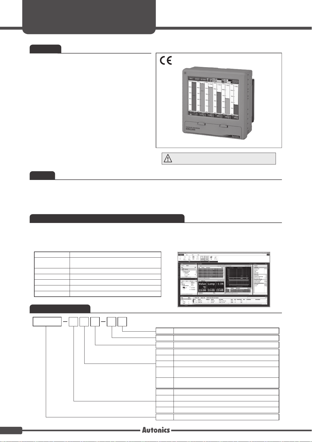
KRN1000
Series
Features
•
5.6-inch color TFT LCD (640×480) touchscreen
display with excellent readability and intuitive control
interface
•
Supports 27 input types (thermocouple, RTD, analog
voltage and current[shunt])
•
4 / 8 / 12 / 16 input channel models available
•
Various communication methods (RS422/485,
Ethernet, USB) standard
•
25 to 250 ms high-speed sampling, 1 to 3600 s
recording cycle
•
200 MB internal memory and external memory
support (SD/USB up to 32 GB)
•
Store and backup internal data to external memory
(SD/USB)
•
9 different graph types available
•
Various option input/output available: digital input
(contact/non-contact), alarm output, transmitter
power output
•
Compact, space-saving design (rear length: 69.2 mm)
Please read “Safety Considerations” in operation manual
before using this unit.
Manual
• For more information and instructions, refer to the user manual and the user manual for communication.
Visit our web site (www.autonics.com) to download the manuals.
• The user manual includes product specications, functions, and operations.
• The user manual for communication includes information about Modbus RTU protocol, Modbus TCP protocol, and Modbus
mapping table.
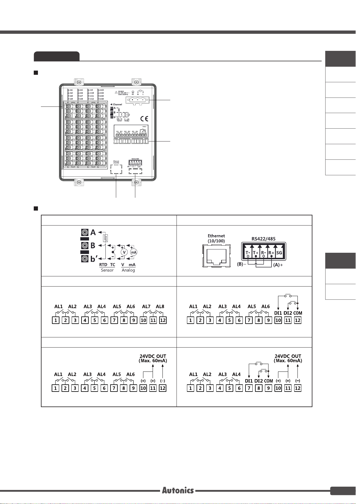
Comprehensive device management program [DAQMaster]
• DAQMaster is the comprehensive device management program for convenient management of parameters and multiple device
data monitoring.
• Visit our website (www.autonics.com) to download user manual and comprehensive device management program.
< Computer specication for using software >
Item Minimum requirements
System
Operating system Microsoft Windows 98/NT/XP/Vista/7/8/10
Memory 256MB or more
Hard disk More than 1GB of free hard disk space
VGA 1024 × 768 or higher resolution display
Others RS-232 serial port (9-pin), USB port
IBM PC compatible computer with Intel Pentium
or above
Ⅲ
< DAQMaster screen >
Ordering information
KRN1000
04
0 1 0 S
Case
Power supply
Communication output
Option input/output
Input channels
Item
S Standard panel installation type
0 100-240VAC 50/60Hz
1 RS422/485+Ethernet+USB Device
0 None
1 Alarm relay output 8 channels
2 Alarm relay output 6 channels + Digital input 2 channels
Alarm relay output 6 channels
3
+ 24VDC power output for transmitter
Alarm relay output 4 channels + Digital input 2 channels
4
+ 24VDC power output for transmitter
04 4 channels
08 8 channels
12 12 channels
16 16 channels
KRN1000
Paperless recorder
A-2
LCD Touchscreen Paperless Recorder
Connections
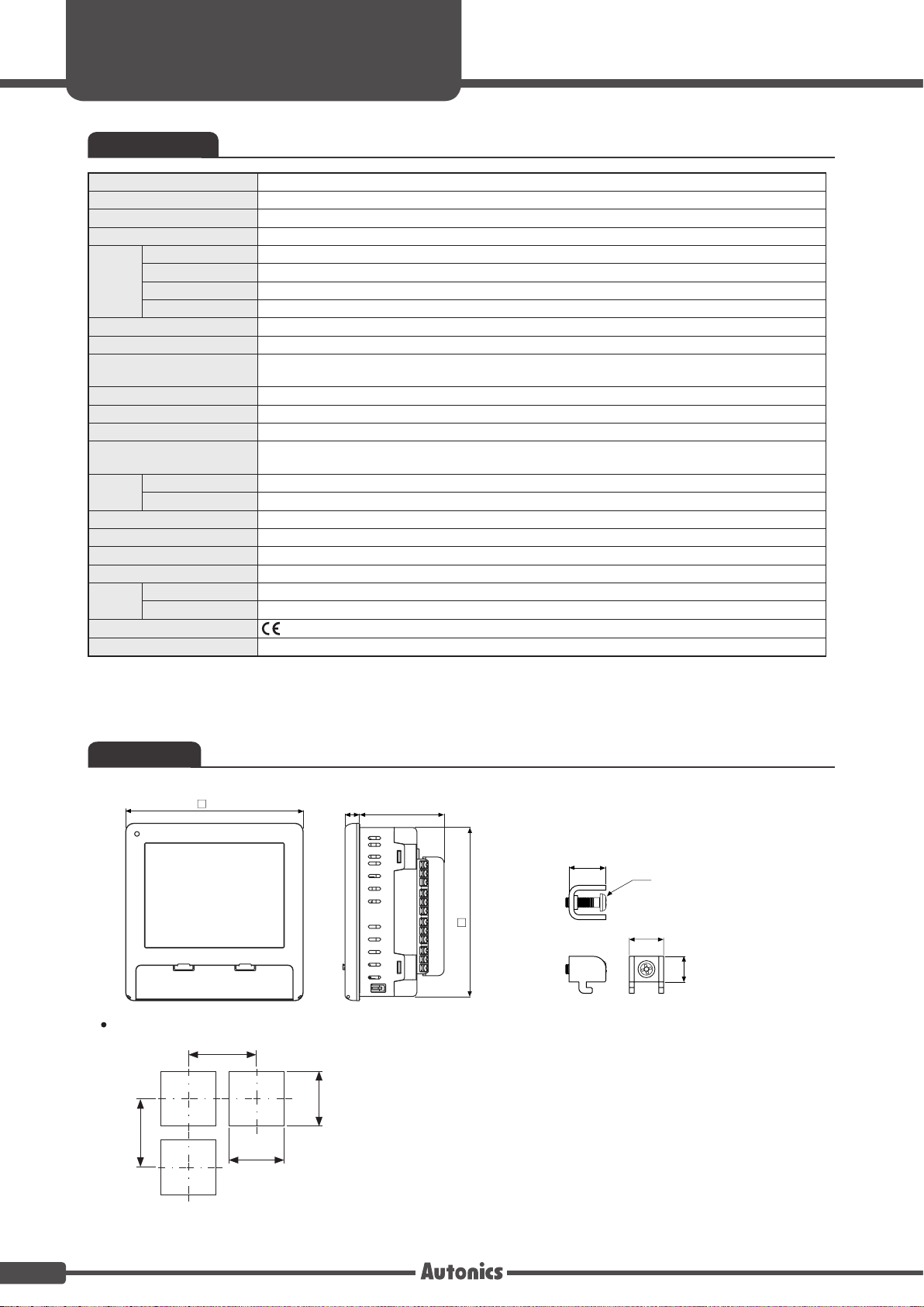
KRN1000 Rear part
①
Input/Output Circuit
②
Universal input
A. Recorders
B. Indicators
Sensor input terminal: Connects universal input.
①
Ethernet port: Connector for ethernet cable.
②
⑤
RS422/485 port: Connects RS422/485 for Modbus
③
It communicates Modbus TCP.
RTU communication.
Option input/output port: Connects for option input/output .
④
Power input: Power connection (100-240VAC 50/60Hz)
⑤
④
③
※
Communication output
C. Converters
D. Controllers
E. Thyristor
power
controllers
F. Pressure
transmitters
G. Temperature
transmitters
H. Accessories
Option input/output 1 Option input/output 2
Alarm output 8 channels Alarm output 6 channels + Digital input 2 channels
Option input/output 3 Option input/output 4
Alarm output 6 channels + Power for transmitter output
※
In case of current input, connect 250Ω resistance at external part.
Alarm output 4 channels + Digital input 2 channels
+ Power for transmitter output
KRN1000
KRN10 0
KRN50
A-3
KRN1000
Series
Specications
Series KRN1000
Power supply 100-240VAC 50/60Hz
Allowable voltage range 85 to 110% of rated voltage
Power consumption Max. 23VA
Display method 5.6 inch TFT Color LCD
Screen
Number of input channels 4 / 8 / 12 / 16 channels
Universal input
Sampling period
Recording period 1 to 3600 sec
Internal memory Approx. 200MB
External memory SD / USB memory max. 32GB
Dielectric strength
Vibration
Insulation resistance Over 20MΩ (at 500VDC megger)
Noise immunity Square shaped noise by noise simulator (pulse width 1µs) ±2kV
Time accuracy Within ±2 min/year (available up to 2099)
Protection structure IP50 (front part)
Environment
Approval
Weight
※1. For more information of universal input, please refer to 「Input/Output」 of the A-5 page.
※
2. The weight includes packaing. The weight in parenthesis is for unit only.
※
Environment resistance is rated at no freezing or condensation.
Resolution 640×480 pixels
Adjusting brightness 3-level (Min/Standard/Max)
Input method Touch screen (pressure sensitive type)
※
1
Mechanical 10 to 60Hz 4.9m/s2 in each X, Y, Z direction for 1 hour
Malfunction 10 to 60Hz 1m/s
Ambient temperature 0 to 50℃, storage: -20 to 60℃
Ambient humidity 35 to 85%RH, storage: 35 to 85%RH
※
2
Temperature sensors (thermocouple, RTD), Analog (voltage, current (shunt))
1 to 4-CH: 25ms/125ms/250ms, 5 to 16-CH: 125ms/250ms
(internal sampling period is average movement lter and alarm output operation unit time)
2300VAC 50/60Hz for 1 min (between power terminals and case)
※
Except ethernet and USB device
2
in each X, Y, Z direction for 10 min
Approx. 1290 to 1400g (approx. 590 to 700g)
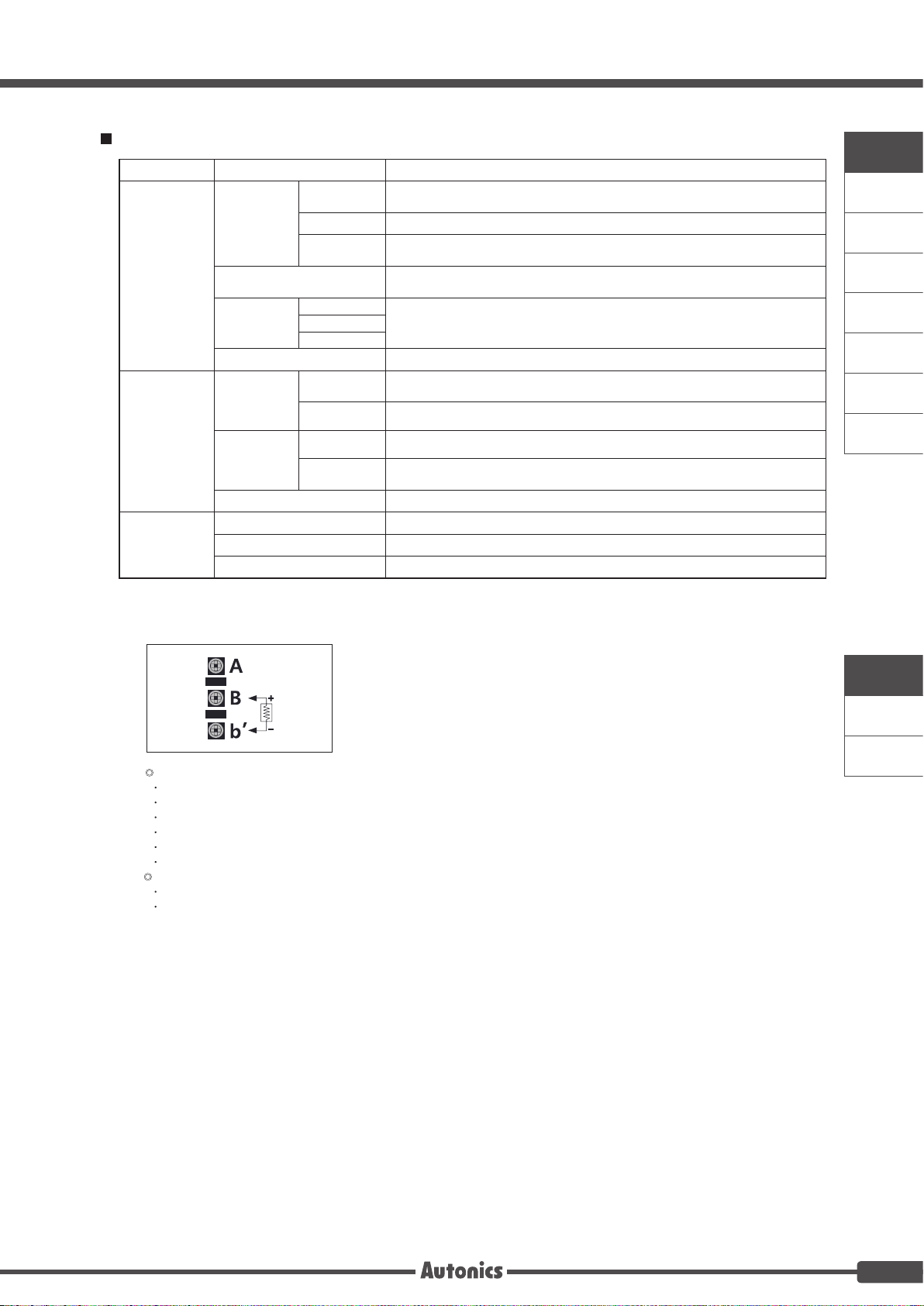
Dimensions
Panel cut-out
Min. 175
144
Min. 175
138
+1.0
0
11.5 69.2
+1.0
0
138
(unit: mm)
15
M4
137.5
14
10.4
A-4
LCD Touchscreen Paperless Recorder
Input/Output
Type Input/Output type Description
RTD
Input type
Thermocouple B, C (W5), E, G, J, K, L, L (Russia), N, P, R, S, T, U
Analog
Universal input
Input impedance
Display
accuracy
※
2
RTD
Thermocouple
Analog
Resolution 16-bit
No-contact
Digital input
input
Contact input ON: Max. 1kΩ, OFF: Min. 100kΩ, Short-circuit: Approx. 4mA
Option
input/output
※
3
Alarm relay
output
Capacity 250VAC 3A, 30VDC 3A, 1 Form A (resistive load)
Life cycle
Power output for transmitter
RS422/485 Modbus RTU ※It is recommended to use shielded cable over AWG 24.
Communication
※
5
output
Ethernet IEEE802.3 10 BASE-T / IEEE802.3U 100 BASE-TX (Modbus TCP)
USB Device USB V2.0 Full Speed (Modbus RTU)
※
1. Current measurement and connection examples
Connect 250Ω shunt resistance and set analog input type 0-20mA (shunt) / 4-20mA (shunt).
It is available to measure 0-20mA / 4-20mA current.
JPt100Ω, DPt100Ω, DPt50Ω, Cu100Ω, Cu50Ω
(supplied current: approx. 190µA)
Voltage: ±60mV, ±200mV, ±2V, 1-5V, ±5V, -1V-10V
Current: 0-20mA, 4-20mA (measureable when using 250Ω shunt resistance)
Voltage (V): Approx. 205kΩ
RTD, Thermocouple, Voltage (mV): Min. 200kΩ
Warm-up time: Max. 30 min
At room temperature (25±5℃): ±0.1% F.S.±1-digit
Out of room temperature: ±0.2% F.S.±1-digit
ON: Residual voltage max. 1V, OFF: Leakage current max. 0.1mA
Mechanical: Min. 20,000,000 operations
Electrical: 100,000 operations (3A 250V AC, 3A 30V DC)
※
4
24±2VDC, Max. 60mA ※Built-in over current protection circuit
※
1
A. Recorders
B. Indicators
C. Converters
D. Controllers
E. Thyristor
power
controllers
F. Pressure
transmitters
G. Temperature
transmitters
H. Accessories
※
At room temperature (23℃ ± 5℃)
2.
RTD Cu50Ω (-200≤T≤200): (±0.1% F.S. or ±1.5℃, select the higher one) ±1 digit
RTD DPt50Ω (-200≤T≤500): (±0.1% F.S. or ±1.5℃, select the higher one) ±1 digit
Thermocouple R, S, C, G type (0≤T≤100): (±0.1% F.S. or ±4.0℃, select the higher one) ±1 digit
Thermocouple U, T type (-100≤T≤400): (±0.1% F.S. or ±2.0℃, select the higher one) ±1 digit
Thermocouple B type, below 400℃: There is no accuracy standards.
All thermocouples, below -100℃: (±0.3% F.S. or ±4.0℃, select the higher one) ±1 digit
Out of room temperature range
RTD Cu50Ω (-200≤T≤200): (±0.2% F.S. or ±3.0℃, select the higher one) ±1 digit
RTD DPt50Ω (-200≤T≤500): (±0.2% F.S. or ±3.0℃, select the higher one) ±1 digit
※
3. Input/Output is different by option.
※
4. For supplying power for transmitter, it is recommened to use shield cable to reduce noise.
※
5. RS422/485, ethernet, USB device communication outputs are not used at the same time.
※
If sensor input line is longer, it is recommended to use shield cable to reduce noise.
Please refer to 「Ordering information」of the A-2 page.
KRN1000
KRN10 0
KRN50
A-5
KRN1000
Input type and range
Series
Input type Display
K(CA) TC-K -200.0 to 1350.0 -328.0 to 2462.0 73.2 to 1623.2
J(IC) TC-J -200.0 to 800.0 -328.0 to 1472.0 73.2 to 1073.2
E(CR) TC-E -200.0 to 800.0 -328.0 to 1472.0 73.2 to 1073.2
T(CC) TC-T -200.0 to 400.0 -328.0 to 752.0 73.2 to 673.2
B(PR) TC-B 100.0 to 1800.0 212.0 to 3272.0 373.2 to 2073.2
R(PR) TC-R 0.0 to 1750.0 32.0 to 3182.0 273.2 to 2023.2
Thermocouple
RTD
Analog
※1. C (TT): Same as existing W5 (TT) type sensor
※2. G (TT): Same as existing W (TT) type sensor
※3. Russian type L type temperature sensor is divided from general purpose L type.
S(PR) TC-S 0.0 to 1750.0 32.0 to 3182.0 273.2 to 2023.2
N(NN) TC-N -200.0 to 1300.0 -328.0 to 2372.0 73.2 to 2023.2
※
1
C(TT)
※
2
G(TT)
L(IC) TC-L -200.0 to 900.0 -328.0 to 1652.0 73.2 to 1173.2
※
L(Russian type)
U(CC) TC-U -200.0 to 400.0 -328.0 to 752.0 73.2 to 673.2
Platinel Ⅱ TC-P 0.0 to 1350.0 32.0 to 2462.0 273.2 to 1623.2
Cu50Ω CU50 -200.0 to 200.0 -328.0 to 392.0 73.2 to 473.2
Cu100Ω CU100 -200.0 to 200.0 -328.0 to 392.0 73.2 to 473.2
JPt100Ω JPT100 -200.0 to 600.0 -328.0 to 1112.0 73.2 to 873.2
DPt50Ω DPT50 -200.0 to 600.0 -328.0 to 1112.0 73.2 to 873.2
DPt100Ω DPT100 -200.0 to 850.0 -328.0 to 1562.0 73.2 to 1123.2
Voltage
Current
(shunt)
3
-60.00 - 60.00mV ±60mV Resolution : 10㎶
-200.00 - 200.00mV ±200mV Resolution : 10㎶
-2.000 - 2.000V ±2V Resolution : 1mV
1.000 - 5.000V 1-5V Resolution : 1mV
-5.000 - 5.000V ±5V Resolution : 1mV
-1.00 - 10.00V -1V-10V Resolution : 10mV
0 - 20mA
4 - 20mA
TC-C 0.0 to 2300.0 32.0 to 4172.0 273.2 to 2573.2
TC-G 0.0 to 2300.0 32.0 to 4172.0 273.2 to 2573.2
TC-L_R 0 to 600.0 32.0 to 1112.0 273.2 to 873.2
0-20mA
(shunt)
4-20mA
(shunt)
℃ ℉
-
-
Input range
K
-99999 to 99999
(display range depends on
the decimal point position)
A-6
 Loading...