

AUO M320DVN01.0 Specification
Product Specification
Preliminary Specification
(ˇ )
( ) Final Specification
Module 32.0” Color TFT-LCD
AU OPTRONICS CORPORATION
M320DVN01.0
Model Name M320DVN01.0
Customer Date
___
Approved by
Approved by Date
Howard Lee
Prepared by Date
Oct 7, 2013
Note: This Specification is subject to
change without notice.
Hannie Yeh
AU Optronics corporation
Oct 7, 2013
AUO Confidential For ACMEPOINT Internal Use Only / 2013/10/15
document version 0.2 1
Product Specification
AU OPTRONICS CORPORATION
M320DVN01.0
Contents
1 Handling Precautions................................................................ 4
2 General Description .................................................................. 5
2.1 Display Characteristics...........................................................................................................5
2.2 Absolute Maximum Rating of Environment ...........................................................................6
2.3 Optical Characteristics ...........................................................................................................7
3 TFT-LCD Module...................................................................... 11
3.1 Block Diagram ......................................................................................................................11
3.2 Interface Connection ........................................................................................................... 12
3.2.1 Connector Type ................................................................................................................ 12
3.2.2 Connector Pin Assignment............................................................................................... 12
3.3 Electrical Characteristics..................................................................................................... 16
3.3.1 Absolute Maximum Rating ............................................................................................... 16
3.3.2 Recommended Operating Condition ............................................................................... 16
3.4 Signal Characteristics.......................................................................................................... 17
3.4.1 LCD Pixel Format ............................................................................................................. 17
3.4.2 LVDS Data Format ........................................................................................................... 18
3.4.3 Color versus Input Data ................................................................................................... 19
3.4.4 LVDS Specification ........................................................................................................... 20
3.4.5 Input Timing Specification................................................................................................. 22
3.4.6 Input Timing Diagram ....................................................................................................... 23
3.5 Power ON/OFF Sequence .................................................................................................. 24
4 Backlight Unit ......................................................................... 25
4.1 Block Diagram ..................................................................................................................... 25
4.2 Interface Connection ........................................................................................................... 26
4.2.1 Connector Type ................................................................................................................ 26
4.3 Electrical Characteristics..................................................................................................... 29
4.3.1 Absolute Maximum Rating ............................................................................................... 29
4.3.2 Recommended Operating Condition ............................................................................... 29
5 Reliability Test........................................................................ 31
6 Shipping Label ........................................................................ 32
7 Mechanical Characteristics ..................................................... 33
8 Packing Specification.............................................................. 34
8.1 Packing Flow ....................................................................................................................... 34
8.2 Pallet and shipment information.......................................................................................... 35
AUO Confidential For ACMEPOINT Internal Use Only / 2013/10/15
document version 0.2 2
Product Specification
AU OPTRONICS CORPORATION
M320DVN01.0
Record of Revision
Version
0.1 2013/7/2 All First version release -
0.2 2013/10/7
28
Date Page Old description New Description Remark
12
TFT-LCD connector vendor:
JAE, Starconn, P-two
Original center reinforced rib
was 211.28mm
Remove Starconn connector
Modify center reinforced rib to
be 178.28mm
30
31
33
Drop test: Height: 60 cm,
package test
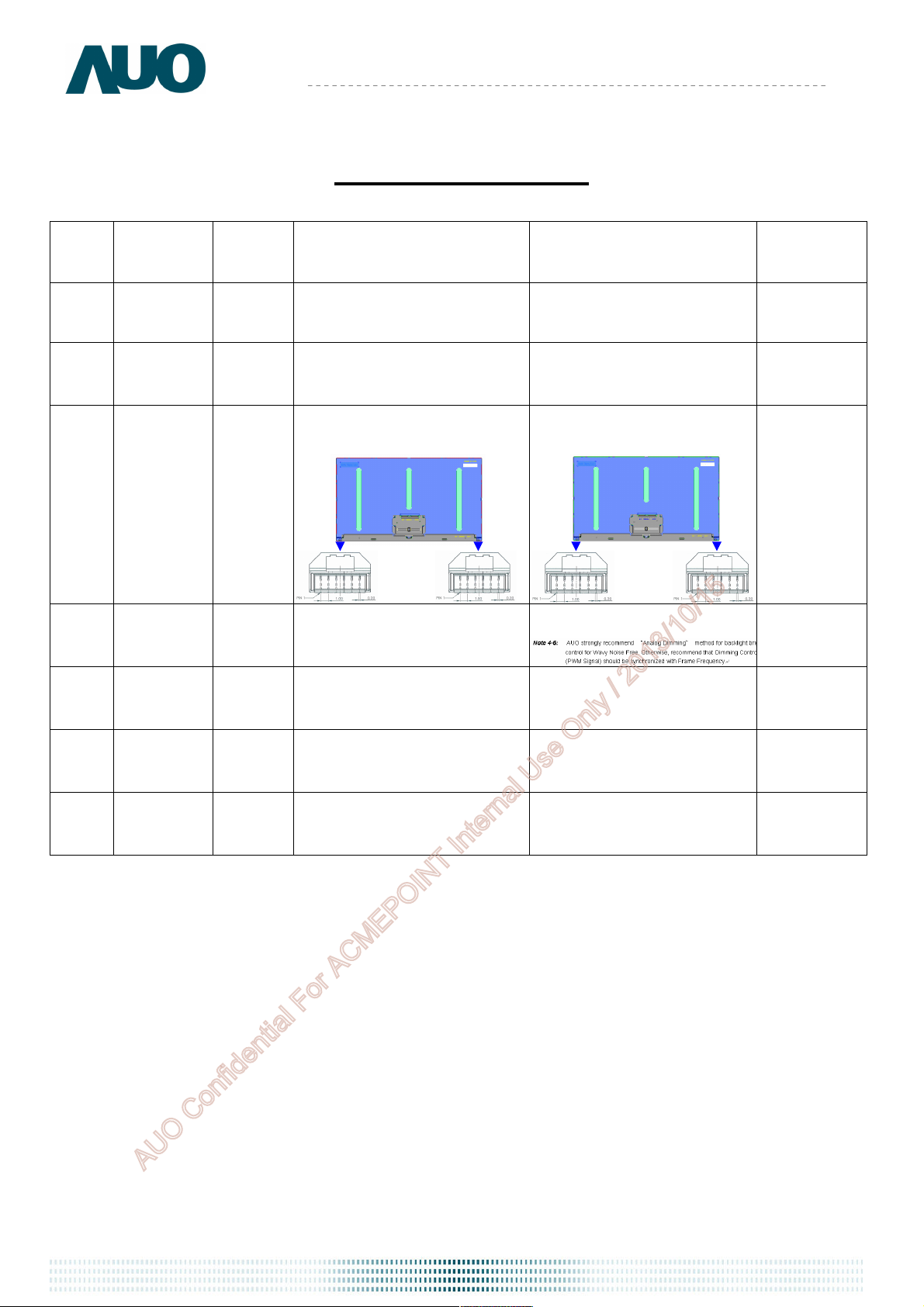
4.3.2 Add Note 4-6
Cancel drop test item
Same as page 28. modify
reinforced rib to be 178.28mm
AUO Confidential For ACMEPOINT Internal Use Only / 2013/10/15
document version 0.2 3
Product Specification
M320DVN01.0
AU OPTRONICS CORPORATION
1 Handling Precautions
1) Since front polarizer is easily damaged, pay attention not to scratch it.
2) Be sure to turn off power supply when inserting or disconnecting from input connector.
3) Wipe off water drop immediately. Long contact with water may cause discoloration or spots.
4) When the panel surface is soiled, wipe it with absorbent cotton or other soft cloth.
5) Since the panel is made of glass, it may break or crack if dropped or bumped on hard surface.
6) Since CMOS LSI is used in this module, take care of static electricity and insure human earth
when handling.
7) Do not open or modify the Module Assembly.
8) Do not press the reflector sheet at the back of the module to any directions.
9) In case a TFT-LCD Module has to be put back into the packing container slot after once it was
taken out from the container, do not press the center of the LED lightbar edge. Otherwise the
TFT-LCD Module may be damaged.
10) Insert or pull out the interface connector, be sure not to rotate nor tilt it of the TFT-LCD
Module.
11) Do not twist nor bend the TFT -LCD Module even momentary. It should be taken into
consideration that no bending/twisting forces are applied to the TFT-LCD Module from outside.
Otherwise the TFT-LCD Module may be damaged.
12) Please avoid touching COF position while you are doing mechanical design.
13) When storing modules as spares for a long time, the following precaution is necessary:
Store them in a dark place. Do not expose the module to sunlight or fluorescent light. Keep the
t
empera
t
b
u
w
t
re
e
5
een
d35
an
t
a
norma
lh
idit
m
u
y
.
AUO Confidential For ACMEPOINT Internal Use Only / 2013/10/15
document version 0.2 4
Product Specification
AU OPTRONICS CORPORATION
M320DVN01.0
2 General Description
This specification applies to the 32.0 inch wide Color a-Si TFT-LCD Module M320DVN01.0.
The display supports the QHD - 2560(H) x 1440(V) screen format and 1.07B colors (10bits
RGB input). The input interface is 4-channel LVDS and this module doesn’t contain an driver
board for backlight.
2.1 Display Characteristics
The following items are characteristics summary on the table under 25
ITEMS Unit SPECIFICATIONS
Screen Diagonal [mm]
Active Area [mm] 708.4 (H) x 398.5 (V)
Pixels H x V - 2560(x3) x 1440
Pixel Pitch [um] 276.75 (per one triad) × 276.75
Pixel Arrangement - R.G.B. Vertical Stripe
Display Mode - VA Mode, Normally Black
White Luminance ( Center ) [cd/m2] 300 (Typ.)
Contrast Ratio - 3000 (Typ.)
Response Time [msec] 12 (Typ., on/off)
Power Consumption
(LCD Module + Backligh unit)
[Watt]
812.8 (32.0”)
41.3 (Typ.)
LCD module : PDD (Typ.)=9.36 @ white pattern, 60Hz, 12V
Backlight unit : PBLU (Typ.) =31.94 @Is=110mA
condition:
Weight [Grams] 5,080
Outline Dimension [mm] 727.88 (H) x 422.07 (V) × 15.1 (D) Typ.
Electrical Interface - 4-channel LVDS
Support Color - 1.07B colors
Surface Treatment - Anti-Glare, 3H
Temperature Range
Operating
Storage (Shipping)
[oC]
[oC]
0 to +50
-20 to +60
RoHS Compliance - RoHS Compliance
TCO Compliance - TCO 6.0 Compliance
AUO Confidential For ACMEPOINT Internal Use Only / 2013/10/15
document version 0.2 5
Product Specification
AU OPTRONICS CORPORATION
M320DVN01.0
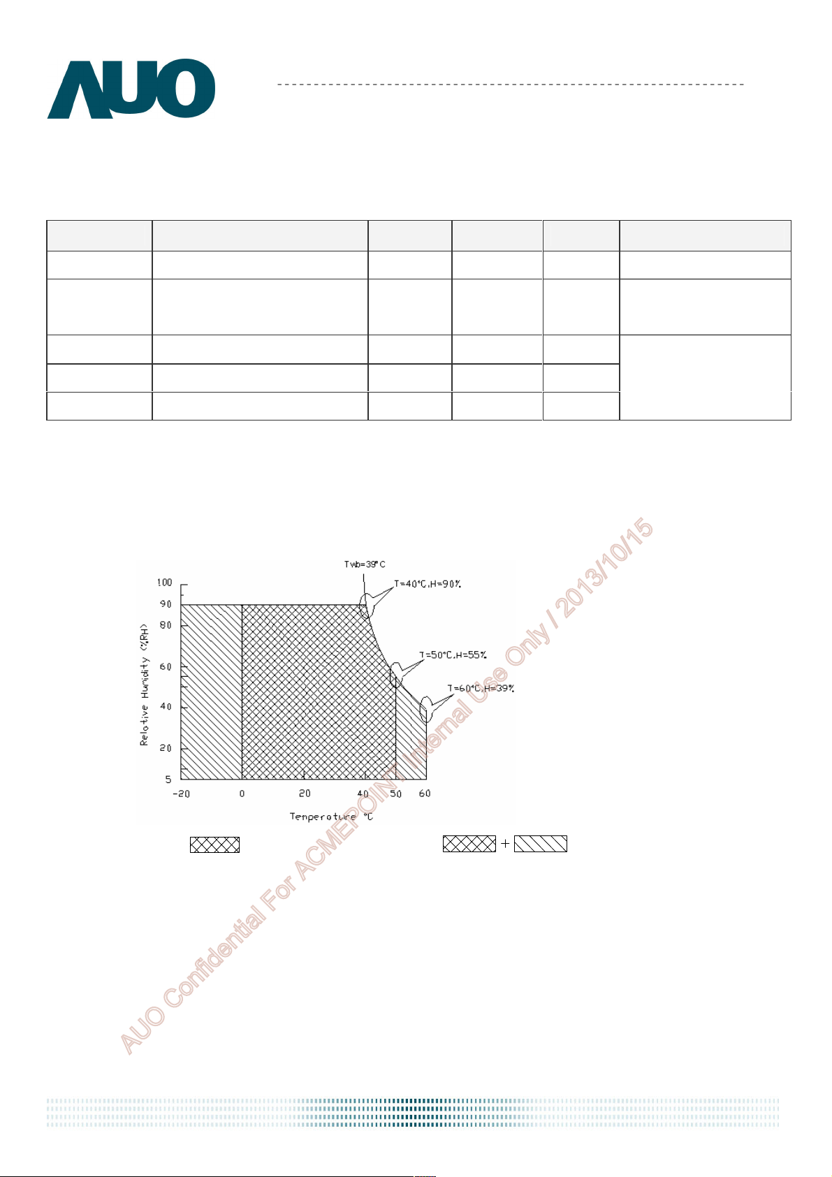
2.2 Absolute Maximum Rating of Environment
Permanent damage may occur if exceeding the following maximum rating.
Symbol Description Min. Max. Unit Remark
TOP Operating Temperature 0 +50 [oC] Note 2-1
TGS
Glass surface temperature
(operation)
0 +65 [oC]
Function judged only
HOP Operation Humidity 5 90 [%RH]
TST Storage Temperature -20 +60 [oC]
HST Storage Humidity
5 90
[%RH]
Note 2-1: Temperature and relative humidity range are shown as the below figure.
1. 90% RH Max ( Ta ≦39℃)
2. Max wet-bulb temperature at 39℃ or less. ( Ta ≦39℃)
3. No condensation
Note 2-1
Note 2-1
Operating Range
Storage Range
AUO Confidential For ACMEPOINT Internal Use Only / 2013/10/15
document version 0.2 6
Product Specification
0.624
0.684
0.303
0.363
0.275
0.335
0.596
0.656
0.116
0.176
0.017
0.077
0.283
0.343
0.299
0.359
AU OPTRONICS CORPORATION
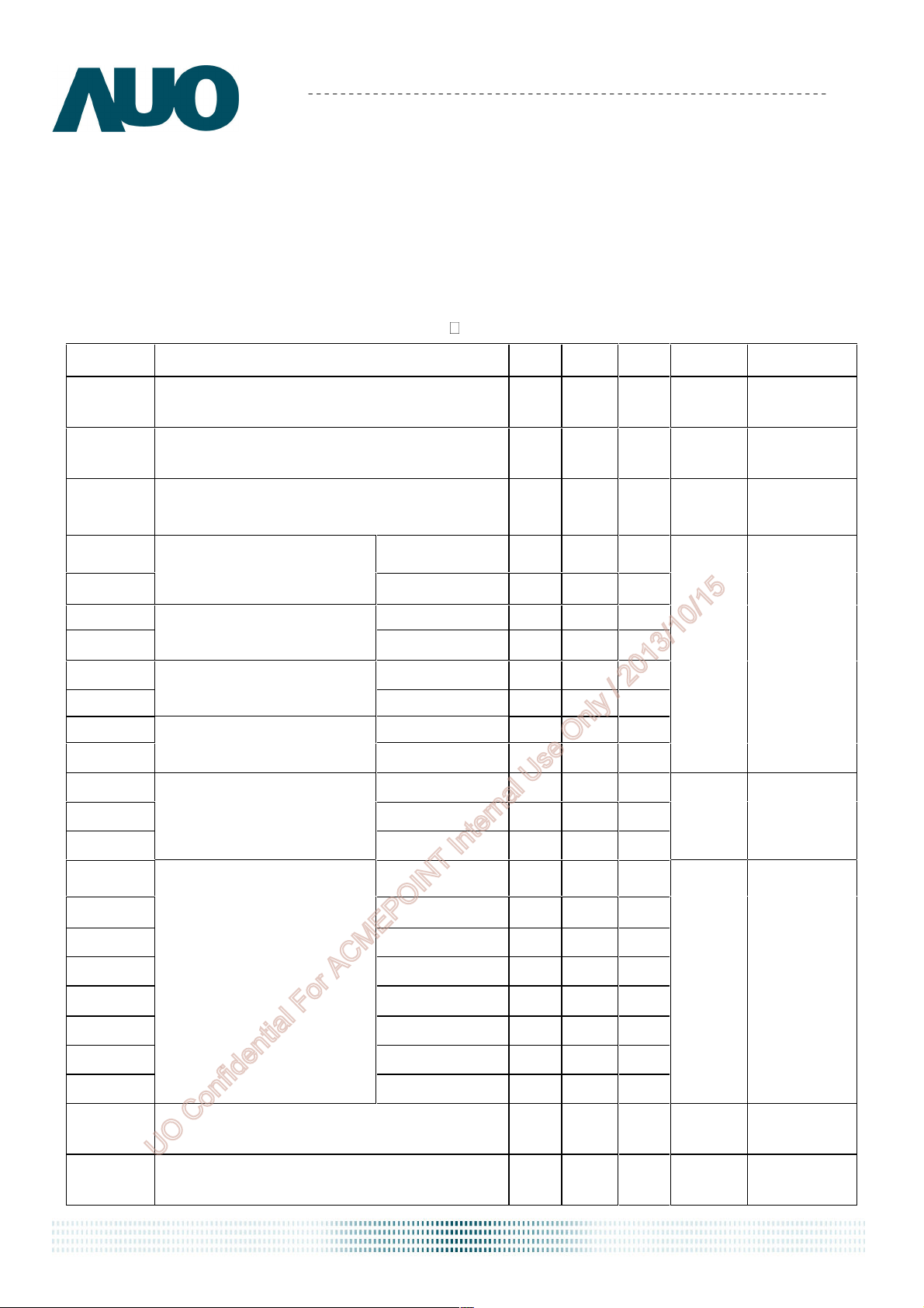
2.3 Optical Characteristics
The optical characteristics are measured on the following test condition.
Test Condition:
1. Equipment setup: Please refer to Note 2-2.
2. Panel Lighting time: 30 minutes
M320DVN01.0
3. VDD=12.0V, Fv=60Hz, Is=110mA,Ta=25
Symbol
Lw White Luminance (Center of screen)
L
Luminance Uniformity (9 points)
uni
Description Min. Typ. Max. Unit Remark
240 300
75 80
CR Contrast Ratio (Center of screen) 1800 3000
θR Right 75 89 -
θL
ΦH
ΦL
θR Right 75 89 -
θL
ΦH
ΦL
Horizontal Viewing Angle
(CR=10)
Vertical Viewing Angle
(CR=10)
Horizontal Viewing Angle
(CR=5)
Vertical Viewing Angle
(CR=5)
Left 75 89 -
Up
75 89 -
Down 75 89 -
Left 75 89 -
Up
75 89 -
Down 75 89 -
[cd/m2]
-
-
[%]
- -
[degree]
Note 2-2
By SR-3
Note 2-3
By SR-3
Note 2-4
By SR-3
Note 2-5
By SR-3
TR Rising Time - 7
TF Falling Time -
-
Rx Red x
Ry Red y
Gx Green x
Gy Green y
Bx Blue x
By Blue y
Wx White x
Wy
Response Time
Color Coordinates
(CIE 1931)
Rising + Falling -
White y
5 -
12 -
0.654
0.333
0.305
0.626
0.146
0.047
0.313
0.329
CT Crosstalk - -
AUO Confidential For ACMEPOINT Internal Use Only / 2013/10/15
FdB Flicker (Center of screen) - -
document version 0.2 7
-
1.5
-20
[msec]
-
[%]
[dB]
Note 2-6
By TRD-100
By SR-3
Note 2-7
By SR-3
Note 2-8
By SR-3

Note 2-2: Equipment setup :
Product Specification
AU OPTRONICS CORPORATION
Photo detector (SR-3, TRD-100)
Measured distance (50cm)
M320DVN01.0
Center of the screen
Note 2-3: Luminance Uniformity Measurement
Definition:
y UniformitLuminance =
a.Test pattern: White Pattern
P9)~(P1 Points 9 of Luminance Minimum
P9)~(P1 Points 9 of Luminance Maximum
AUO Confidential For ACMEPOINT Internal Use Only / 2013/10/15
document version 0.2 8
Product Specification
T
Black
1 Frame
T
AU OPTRONICS CORPORATION
Note 2-4: Contrast Ratio Measurement
Definition:
RatioContrast =
M320DVN01.0
pattern Whiteof Luminance
pattern Black of Luminance
a. Measured position: Center of screen (P5) & perpendicular to the screen (θ=Φ=0°)
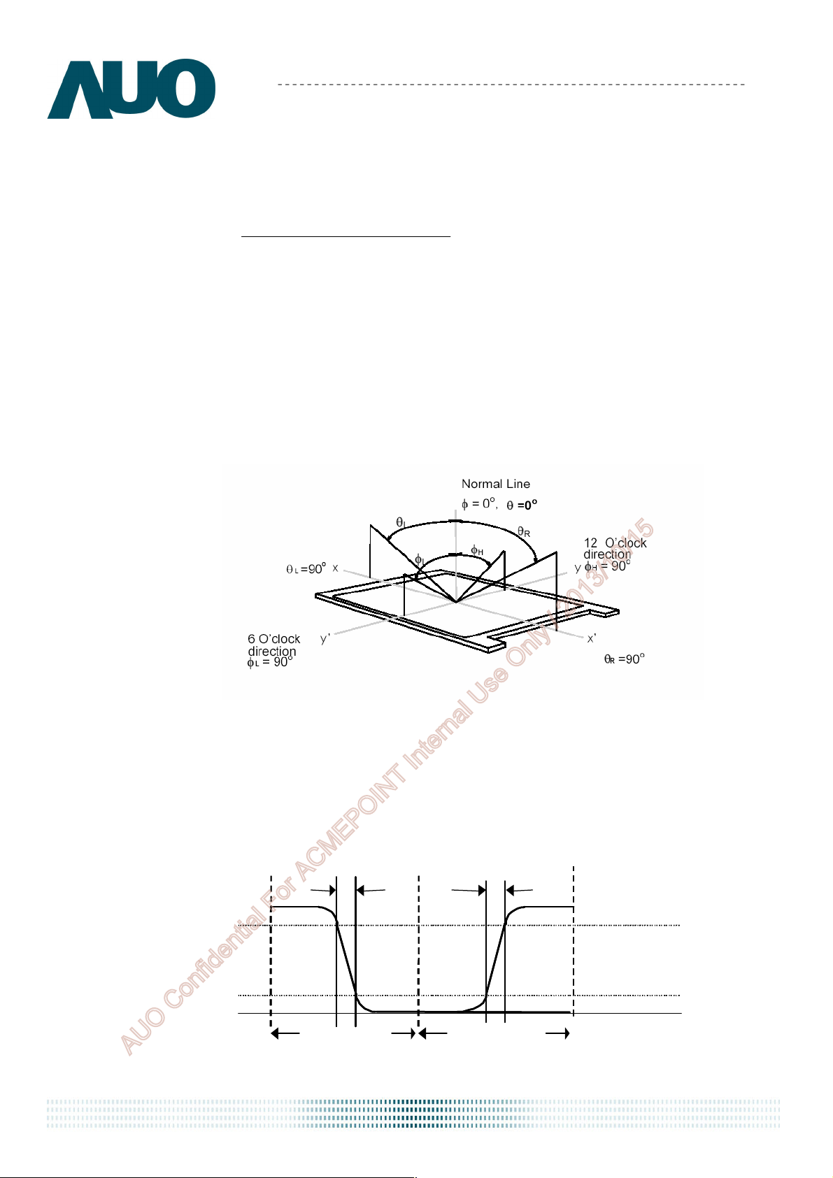
Note 2-5: Viewing angle measurement
Definition: The angle at which the contrast ratio is greater than 10 & 5 .
a. Horizontal view angle: Divide to left & right (θ
Vertical view angle: Divide to up & down (Φ
L & θR
&ΦL)
H
)
Note 2-6: Response time measurement
The output signals of photo detector are measured when the input signals are changed
from “Black” to “White” (rising time, T
), and from “White” to “Black” (falling time, TF),
R
respectively. The response time is interval between the 10% and 90% of optical
response. (Black & White color definition: Please refer section 3.4.3)
Optica l
Optica l
resp on se
resp on se
10 0
10 0
90
10
10
%
%
White
0
0
F
1 Frame
B lack
R
White
AUO Confidential For ACMEPOINT Internal Use Only / 2013/10/15
document version 0.2 9
Product Specification
AU OPTRONICS CORPORATION
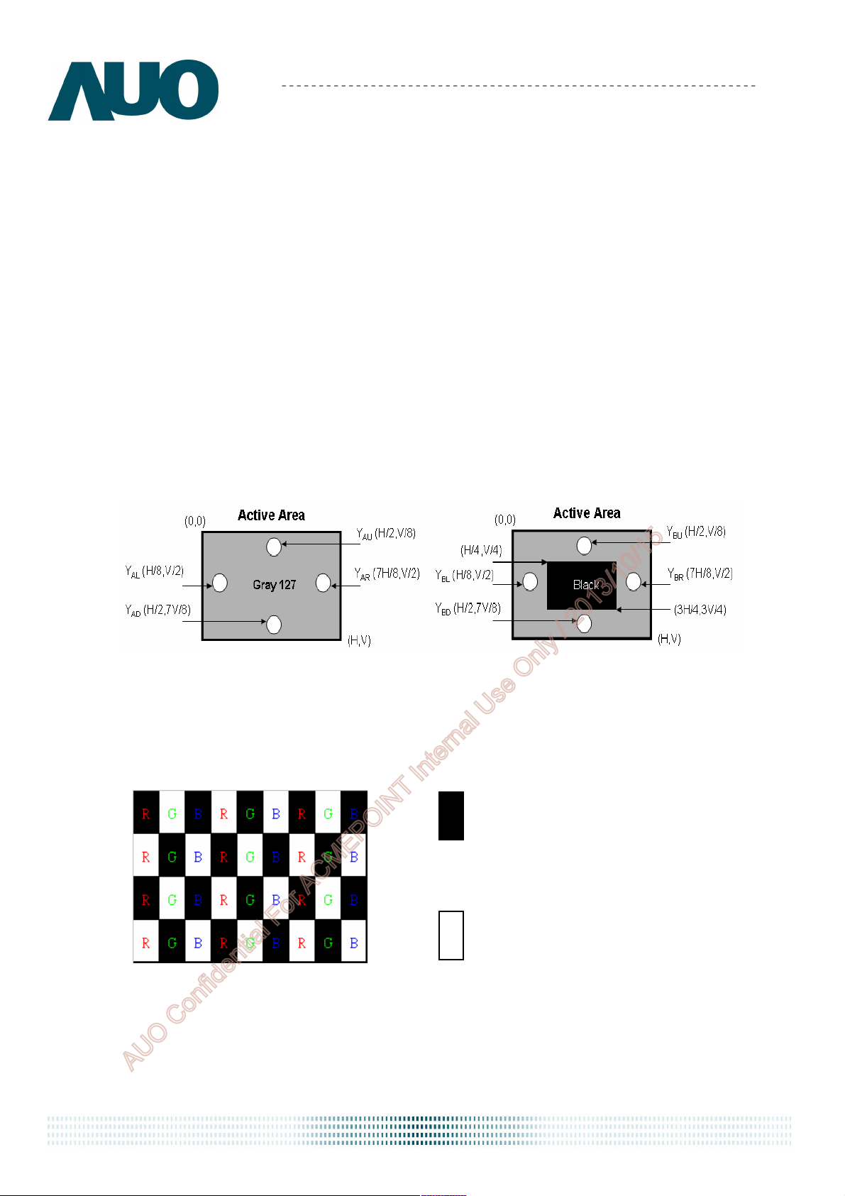
Note 2-7: Crosstalk measurement
Definition:
CT = Max. (CTH,CTV);
Where
a.Maximum Horizontal Crosstalk :
CTH = Max. (| YBL – YAL | / YAL × 100 %, | YBR – YAR | / YAR × 100 %);
Maximum Vertical Crosstalk:
CTV = Max. (| YBU – YAU | / YAU × 100 %, | YBD – YAD | / YAD × 100 %);
b. YAU, YAD, YAL, YAR = Luminance of measured location without Black pattern
YBU, YBD, YBL, YBR = Luminance of measured location with Black pattern
M320DVN01.0
Note 2-8: Flicker measurement
a. Test pattern: It is listed as following.
Gray level = L0
Gray level = L511
R: Red, G: Green, B:Blue
b. Measured position: Center of screen (P5) & perpendicular to the screen (θ=Φ=0°)
document version 0.2 10
AUO Confidential For ACMEPOINT Internal Use Only / 2013/10/15

Product Specification
VLED (4CH)
x 2
X-Driver IC
Y
-
Dr
iver IC
(51 pin)
(41 pin)
AU OPTRONICS CORPORATION
M320DVN01.0
3 TFT-LCD Module
3.1 Block Diagram
The following shows the block diagram of the 32.0 inch Color TFT-LCD Module.
LVDS
2port
VDD
LVDS
2port
CNT1
LVDS
Receiver
CNT2
AUO
ASIC
Timing
Controller
miniLVDS
Transmitter
G1
TFT-LCD
2560(x3) x 1440
Pixels
G1440
D1
D7680
LED
Backlight
DC/DC
Converter
I/F + X-PCB
Gamma
Correction
LED Driver on system
document version 0.2 11
AUO Confidential For ACMEPOINT Internal Use Only / 2013/10/15
 Loading...