

Audi A6´05 323, A6 2005 Service
Audi A6´05
Self-Study Programme 323
Service Training
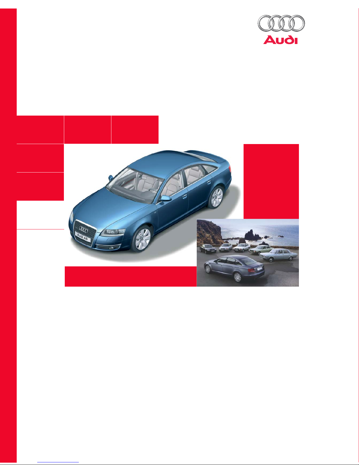
The new Audi A6 – the most progressive vehicle takes the lead
Design and performance are the main driving
elements on its way to the top position.
Furthermore, the new Audi A6 embodies the
consequent continuation of the familiar Audi brand
values, sports appeal, progressiveness and intrinsic
quality, which are evident in the fourth generation
of this sporty business limousine.
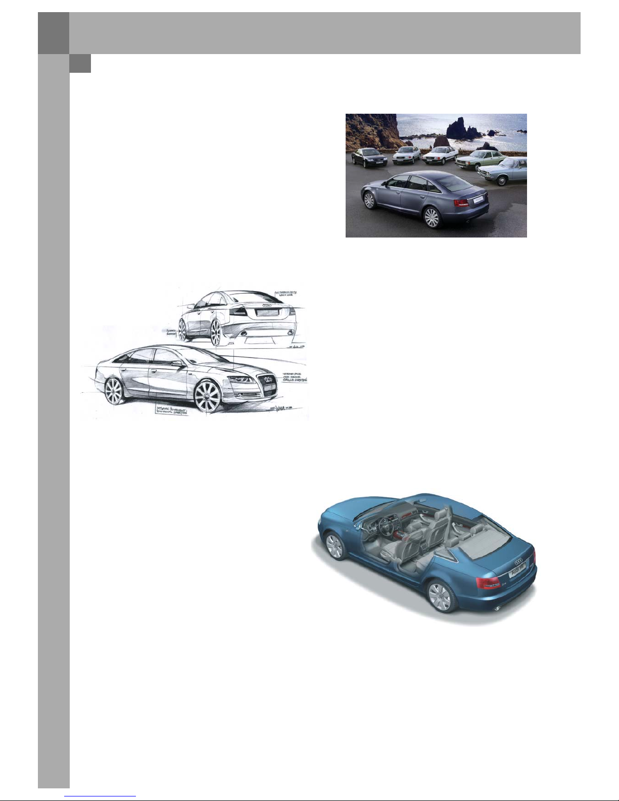
”Vorsprung durch Technik” – this guiding principle is
consistently maintained in the new Audi A6´05
through its innovative technologies.
Highly dynamic chassis technologies are combined
with consumption-optimized drives with the latest
FSI or TDI technology for greater driving pleasure.
Rounded off with servotronic and the 6-stage
tiptronic system with sport programme, the new
Audi A6´05 has optimal driving dynamics as well a
sporty and comfortable tune-up.
The MMI operating system in the interior of the
vehicle is the central control for the extensive
functionalities. The driver-orientated cockpit design
provides a perfect workplace, which is both stylish
and sophisticated. The high functionality is
emphasized by the customer-orientated features in
the safety and convenience function areas.
Preface
NoteReference
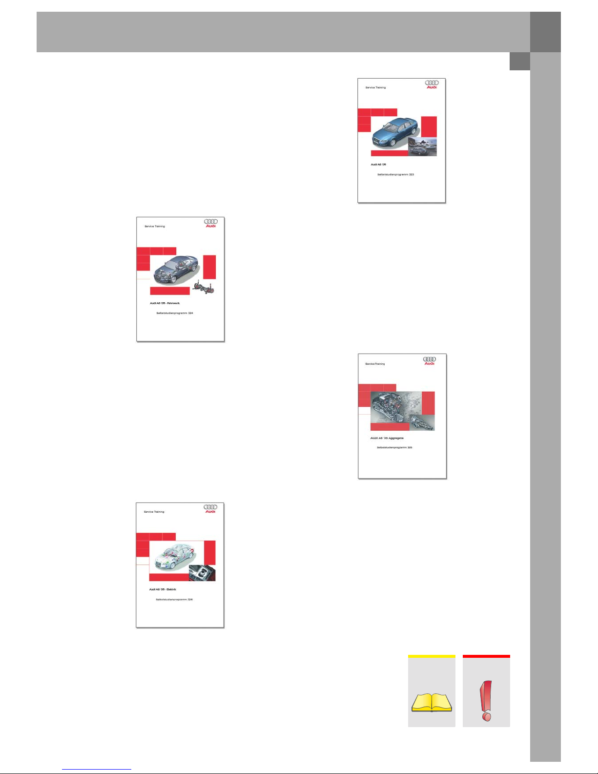
Self-study programmes for the Audi A6´05
The Self-Study Programme provides information on the fundamentals of the design and function of new
vehicle models, new vehicle components or new technologies.
The Self-Study Programme is not a Workshop Manual!
Specified values serve only to make the information easier to understand and relate to the software version
that was valid at the time the Self-Study Programme (SSP) was created.
For maintenance and repair work, please make sure to use the current technical documentation.
323_057
323_058
323_059
323_056
SSP 324 Audi A6´05 Chassis
– Front axle technology
– Rear axle technology
– Steering system
– ESP
– Electromechanical parking brake EPB
Order No.:
A04.5S00.07.20
SSP 326 Audi A6 ´05 Electrics
– Networking
– Bus topologies
– Convenience electrics
– Infotainment
Order No.:
A04.5S00.09.20
SSP 323 Audi A6´05
– Introduction to the vehicle
– Body technology
– Passenger protection
– Air conditioning
Order No.:
A04.5S00.06.20
SSP 325 Audi A6 ´05 Engines
and Gears
– 3.0 V6 TDI Common Rail
– 3.2 litre V6 FSI
– Manual gearbox 01X, 02X, 0A3
– 6-stage automatic transmission 09L
– Multitronic 01J
Order No.:
A04.5S00.08.20

Chapter 1 Introduction
Chapter 3 Passenger protection
Contents
Safety system . . . . . . . . . . . . . . . . . . . . . . . . . . . . . . . . . . . . . . . . . . . . . . . . . . . . . . . . . . . . . . . . . . . . 20
Airbag control unit J234 . . . . . . . . . . . . . . . . . . . . . . . . . . . . . . . . . . . . . . . . . . . . . . . . . . . . . . . . . . . 22
Data exchange. . . . . . . . . . . . . . . . . . . . . . . . . . . . . . . . . . . . . . . . . . . . . . . . . . . . . . . . . . . . . . . . . . . . 23
Sensors . . . . . . . . . . . . . . . . . . . . . . . . . . . . . . . . . . . . . . . . . . . . . . . . . . . . . . . . . . . . . . . . . . . . . . . . . . 24
Belt warning. . . . . . . . . . . . . . . . . . . . . . . . . . . . . . . . . . . . . . . . . . . . . . . . . . . . . . . . . . . . . . . . . . . . . . 26
Airbag . . . . . . . . . . . . . . . . . . . . . . . . . . . . . . . . . . . . . . . . . . . . . . . . . . . . . . . . . . . . . . . . . . . . . . . . . . . 27
Airbag disabling key switch, front passenger side E224 . . . . . . . . . . . . . . . . . . . . . . . . . . . . . . . 31
Seat belts and belt tensioners N153 and N154 . . . . . . . . . . . . . . . . . . . . . . . . . . . . . . . . . . . . . . . 31
Active head restraints . . . . . . . . . . . . . . . . . . . . . . . . . . . . . . . . . . . . . . . . . . . . . . . . . . . . . . . . . . . . . 33
Battery cut-off relay J655 . . . . . . . . . . . . . . . . . . . . . . . . . . . . . . . . . . . . . . . . . . . . . . . . . . . . . . . . . . 34
Seat occupied recognition, not for USA . . . . . . . . . . . . . . . . . . . . . . . . . . . . . . . . . . . . . . . . . . . . . .36
Seat occupied recognition for USA market . . . . . . . . . . . . . . . . . . . . . . . . . . . . . . . . . . . . . . . . . . . 37
Seat occupied recognition control unit J706 . . . . . . . . . . . . . . . . . . . . . . . . . . . . . . . . . . . . . . . . . 40
Chapter 5 Engine / Gearbox
Overview of available engine / gearbox combinations . . . . . . . . . . . . . . . . . . . . . . . . . . . . . . . . . 46
Product highlights. . . . . . . . . . . . . . . . . . . . . . . . . . . . . . . . . . . . . . . . . . . . . . . . . . . . . . . . . . . . . . . . . . 6
Dimensions. . . . . . . . . . . . . . . . . . . . . . . . . . . . . . . . . . . . . . . . . . . . . . . . . . . . . . . . . . . . . . . . . . . . . . . . 7
Chapter 7 Electrics
Bus topology . . . . . . . . . . . . . . . . . . . . . . . . . . . . . . . . . . . . . . . . . . . . . . . . . . . . . . . . . . . . . . . . . . . . . 54
In/outputs on control units J393, J519 and J520 . . . . . . . . . . . . . . . . . . . . . . . . . . . . . . . . . . . . . . 56

Overview . . . . . . . . . . . . . . . . . . . . . . . . . . . . . . . . . . . . . . . . . . . . . . . . . . . . . . . . . . . . . . . . . . . . . . . . . 48
Front axle . . . . . . . . . . . . . . . . . . . . . . . . . . . . . . . . . . . . . . . . . . . . . . . . . . . . . . . . . . . . . . . . . . . . . . . . 48
Rear axle . . . . . . . . . . . . . . . . . . . . . . . . . . . . . . . . . . . . . . . . . . . . . . . . . . . . . . . . . . . . . . . . . . . . . . . . . 49
Wheel brake . . . . . . . . . . . . . . . . . . . . . . . . . . . . . . . . . . . . . . . . . . . . . . . . . . . . . . . . . . . . . . . . . . . . . . 50
ESP . . . . . . . . . . . . . . . . . . . . . . . . . . . . . . . . . . . . . . . . . . . . . . . . . . . . . . . . . . . . . . . . . . . . . . . . . . . . . . 51
Electromechanical parking brake – EPB . . . . . . . . . . . . . . . . . . . . . . . . . . . . . . . . . . . . . . . . . . . . . .51
Steering system. . . . . . . . . . . . . . . . . . . . . . . . . . . . . . . . . . . . . . . . . . . . . . . . . . . . . . . . . . . . . . . . . . . 52
Wheels / tires . . . . . . . . . . . . . . . . . . . . . . . . . . . . . . . . . . . . . . . . . . . . . . . . . . . . . . . . . . . . . . . . . . . . . 53
Tire pressure control system . . . . . . . . . . . . . . . . . . . . . . . . . . . . . . . . . . . . . . . . . . . . . . . . . . . . . . . 53
Chaper 2 Body
Contents
Body shell / connection technology . . . . . . . . . . . . . . . . . . . . . . . . . . . . . . . . . . . . . . . . . . . . . . . . . . 8
Materials . . . . . . . . . . . . . . . . . . . . . . . . . . . . . . . . . . . . . . . . . . . . . . . . . . . . . . . . . . . . . . . . . . . . . . . . . 10
Blanks . . . . . . . . . . . . . . . . . . . . . . . . . . . . . . . . . . . . . . . . . . . . . . . . . . . . . . . . . . . . . . . . . . . . . . . . . . . 12
Assemblies . . . . . . . . . . . . . . . . . . . . . . . . . . . . . . . . . . . . . . . . . . . . . . . . . . . . . . . . . . . . . . . . . . . . . . . 14
Bumpers . . . . . . . . . . . . . . . . . . . . . . . . . . . . . . . . . . . . . . . . . . . . . . . . . . . . . . . . . . . . . . . . . . . . . . . . . 16
Trailer coupling . . . . . . . . . . . . . . . . . . . . . . . . . . . . . . . . . . . . . . . . . . . . . . . . . . . . . . . . . . . . . . . . . . . 17
Chapter 4 Diagnosis
Chapter 6 Chassis
Overview . . . . . . . . . . . . . . . . . . . . . . . . . . . . . . . . . . . . . . . . . . . . . . . . . . . . . . . . . . . . . . . . . . . . . . . . . 58
Convenience automatic air conditioning and convenience automatic
air conditioning plus. . . . . . . . . . . . . . . . . . . . . . . . . . . . . . . . . . . . . . . . . . . . . . . . . . . . . . . . . . . . . . . 60
CAN networking . . . . . . . . . . . . . . . . . . . . . . . . . . . . . . . . . . . . . . . . . . . . . . . . . . . . . . . . . . . . . . . . . . 61
Components in the Audi A6 ´05 air conditioning unit . . . . . . . . . . . . . . . . . . . . . . . . . . . . . . . . . . 64
Replacing components . . . . . . . . . . . . . . . . . . . . . . . . . . . . . . . . . . . . . . . . . . . . . . . . . . . . . . . . . . . . 66
Control motor versions . . . . . . . . . . . . . . . . . . . . . . . . . . . . . . . . . . . . . . . . . . . . . . . . . . . . . . . . . . . . 68
In/output signals at Climatronic control unit J255 . . . . . . . . . . . . . . . . . . . . . . . . . . . . . . . . . . . . . 69
Additional electric air heater . . . . . . . . . . . . . . . . . . . . . . . . . . . . . . . . . . . . . . . . . . . . . . . . . . . . . . . . 71
Auxiliary / additional heating . . . . . . . . . . . . . . . . . . . . . . . . . . . . . . . . . . . . . . . . . . . . . . . . . . . . . . . 72
Air conditioning diagnosis . . . . . . . . . . . . . . . . . . . . . . . . . . . . . . . . . . . . . . . . . . . . . . . . . . . . . . . . . 74
Special tools for the Audi A6´05 air conditioning system . . . . . . . . . . . . . . . . . . . . . . . . . . . . . . . 75
Chapter 8 Air conditioning
VAS 5053 . . . . . . . . . . . . . . . . . . . . . . . . . . . . . . . . . . . . . . . . . . . . . . . . . . . . . . . . . . . . . . . . . . . . . . . . 42
VAS 5051 . . . . . . . . . . . . . . . . . . . . . . . . . . . . . . . . . . . . . . . . . . . . . . . . . . . . . . . . . . . . . . . . . . . . . . . . 43
VAS 5053/20. . . . . . . . . . . . . . . . . . . . . . . . . . . . . . . . . . . . . . . . . . . . . . . . . . . . . . . . . . . . . . . . . . . . . . 44
Recording the working time using the VAS 5051 / 5052 . . . . . . . . . . . . . . . . . . . . . . . . . . . . . . . 45
6
Introduction
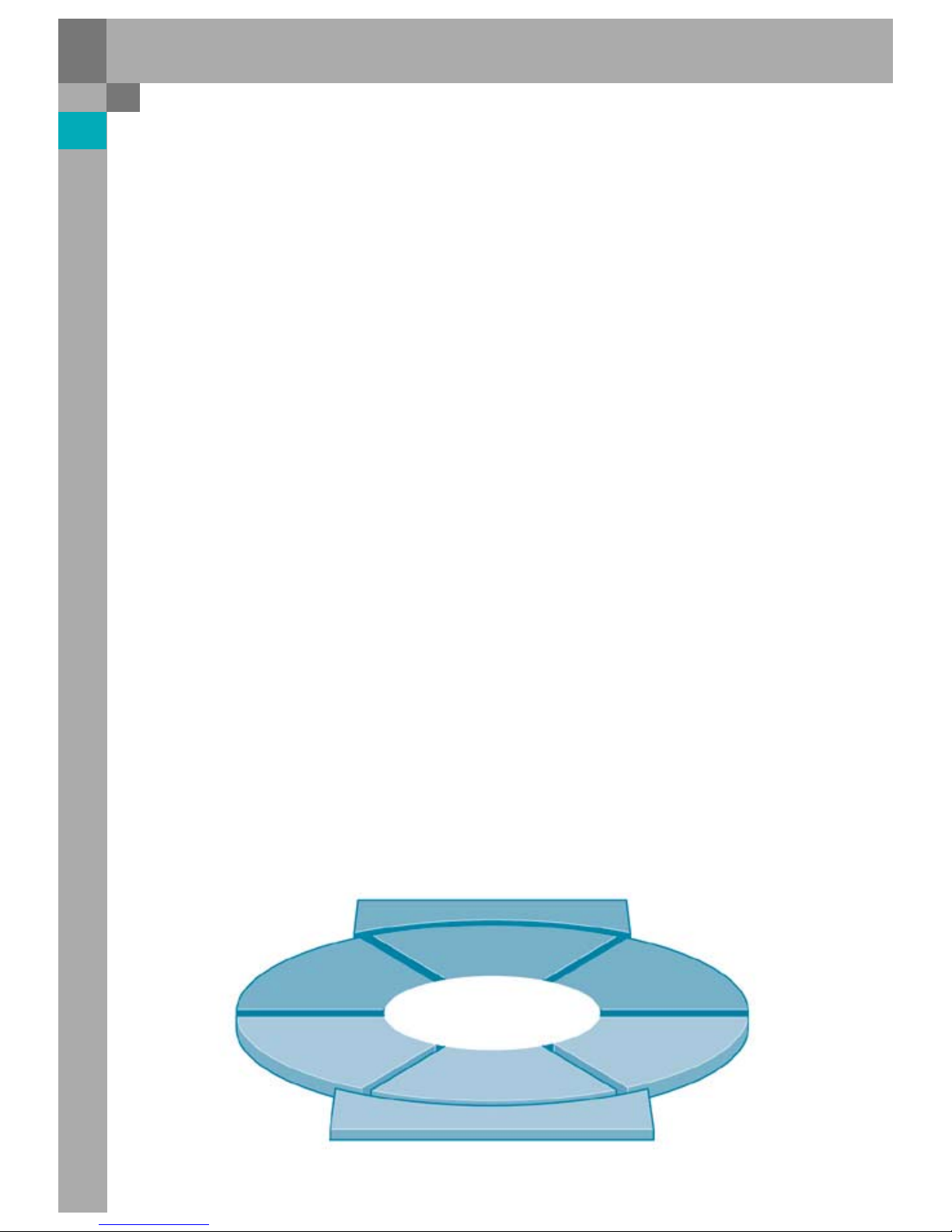
Product highlights
The product features which support the new Audi A6´05 on its way to the top, can be summarised as follows:
One wing is the design, the other wing is the car’s performance.
Performance
Power train s
– Power-controlled power trains, better than
competition
– New FSI technology from motor racing
– New TDI technology common rail II with
Piezo injectors
– Quattro:
– Multitronic
– 6-stage Tiptronic
– Wide selection of motors and gearboxes
Innovation
– FSI
– Common rail II with piezo injectors
– Expanded ESP
– MMI as standard
– Integrated driver cockpit
– Electromechanical parking brake
– Advanced key, adaptive light, LED brake lights,
comfort climate control plus
Driving dynamics
– New dynamic chassis with trapezoidal-link rear
axle and redesigned four-link front axle
– Increased body stiffness + 35 %
– Larger tyre diameter
– Servotronic now standard
– Wider tread widths, front +7 cm, rear +6 cm
– Excellent rear downforce for safe handling
Design
Quality
– Use of intrinsically valuable materials
(aluminium, wood, leather)
– High-quality standard equipment (light-rain
sensor, aluminium trim, active headrests in front,
servotronic, EPB, fog headlights, ...)
– Highest safety standards (5 star Euro NCAP)
– Small gap widths, even joints
Pack age
– Premium vehicle dimensioning
– Rear knee room 8 cm
– Wider shoulder widths, front +23 mm,
rear +6 mm
– Front headroom +7 mm
– Superior luggage compartment volume (546 l) for
front-wheel and quattro models
– Wheelbase +9 cm
Exterior/Interior
– Completely new line design (roofline, shoulder
line, dynamic line)
– Dynamic joint matching
– Coupe-like shape
– Separation edge on rear end
– Single frame
– Double-pipe exhaust for front-wheel and
quattro models
– Full exterior surface painted
Performance
Design
323_038
Driving dynamics
Pack age
Innovation
Pow er trains
Quality
Exterior/Interior
The most
progressive car
takes the lead
7
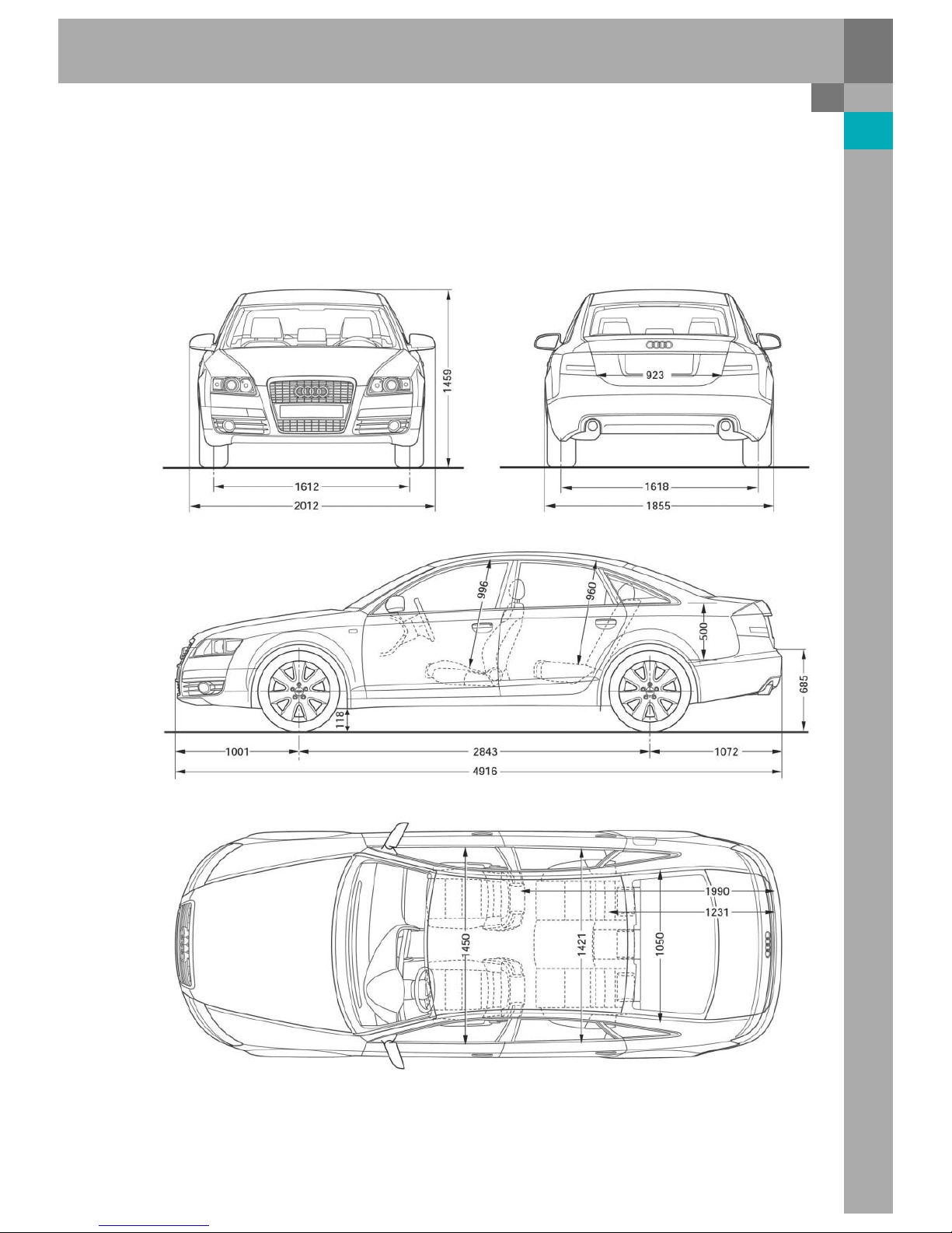
Dimensions
The new Audi A6´05 impresses with its imposing external dimensions.
The vehicle length has been increased to 4.92 m, which corresponds to an increase of 12 cm compared to its
predecessor. The vehicle width has been increased by 4.5 cm to 1.86 m. The height of the new A6´05 has been
increased by 0.8 cm to 1.46 m. The new Audi A6´05 has grown. For the dimensions, please refer to the
diagrams.
323_034
8
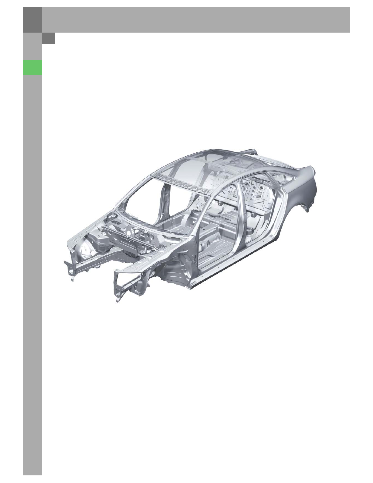
Body shell / connection
technology
The main objectives during the development of the
new Audi A6 body design were the realization of
high passive safety characteristics and improved
rigidity values as a precondition for optimizing
vibration damping characteristics.
Body
In spite of the greater demands compared with
the previous model, the body weight has been kept
at the same level.
A further task during the body development process
is to minimize the number of necessary body
versions.
The new A6´05 uses four body shell versions:
– rigid rear panel
– with opening for loading
– without sliding sunroof
– with sliding sunroof
A standard rear section is used for the front-wheel
drive and quattro vehicles.
323_001
9
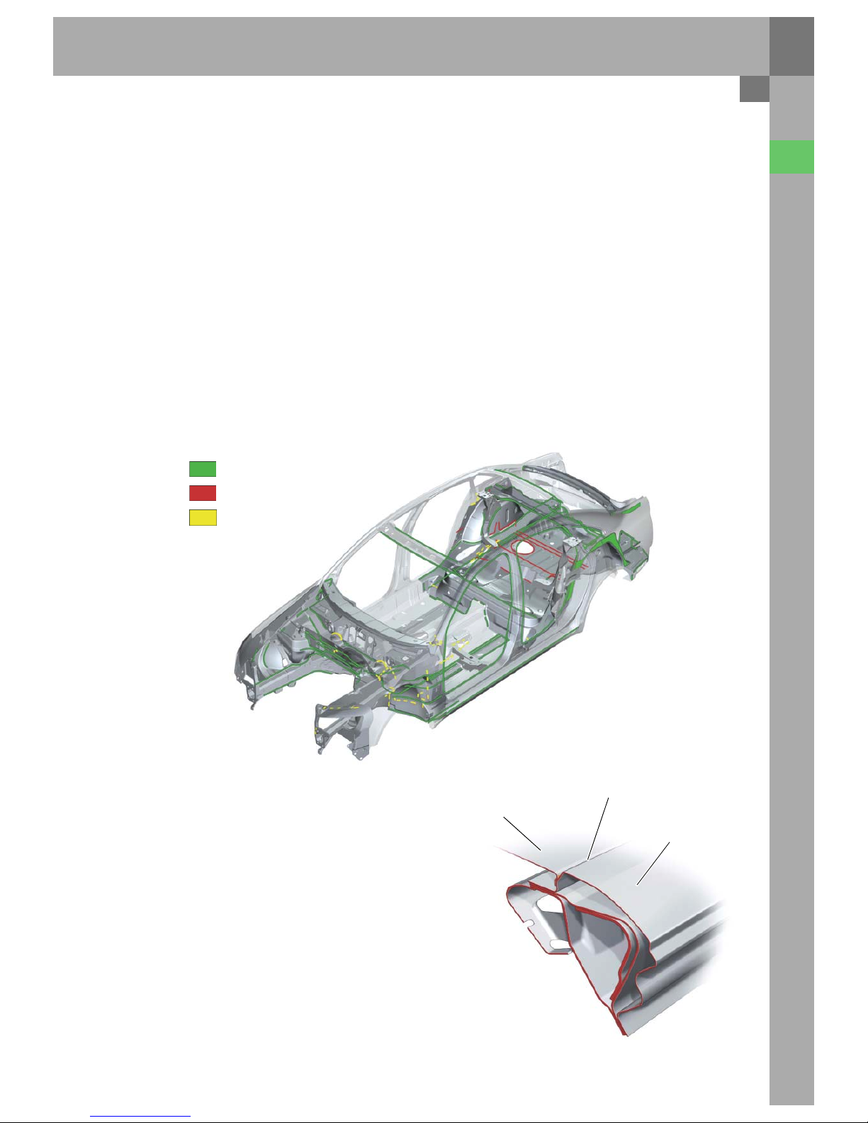
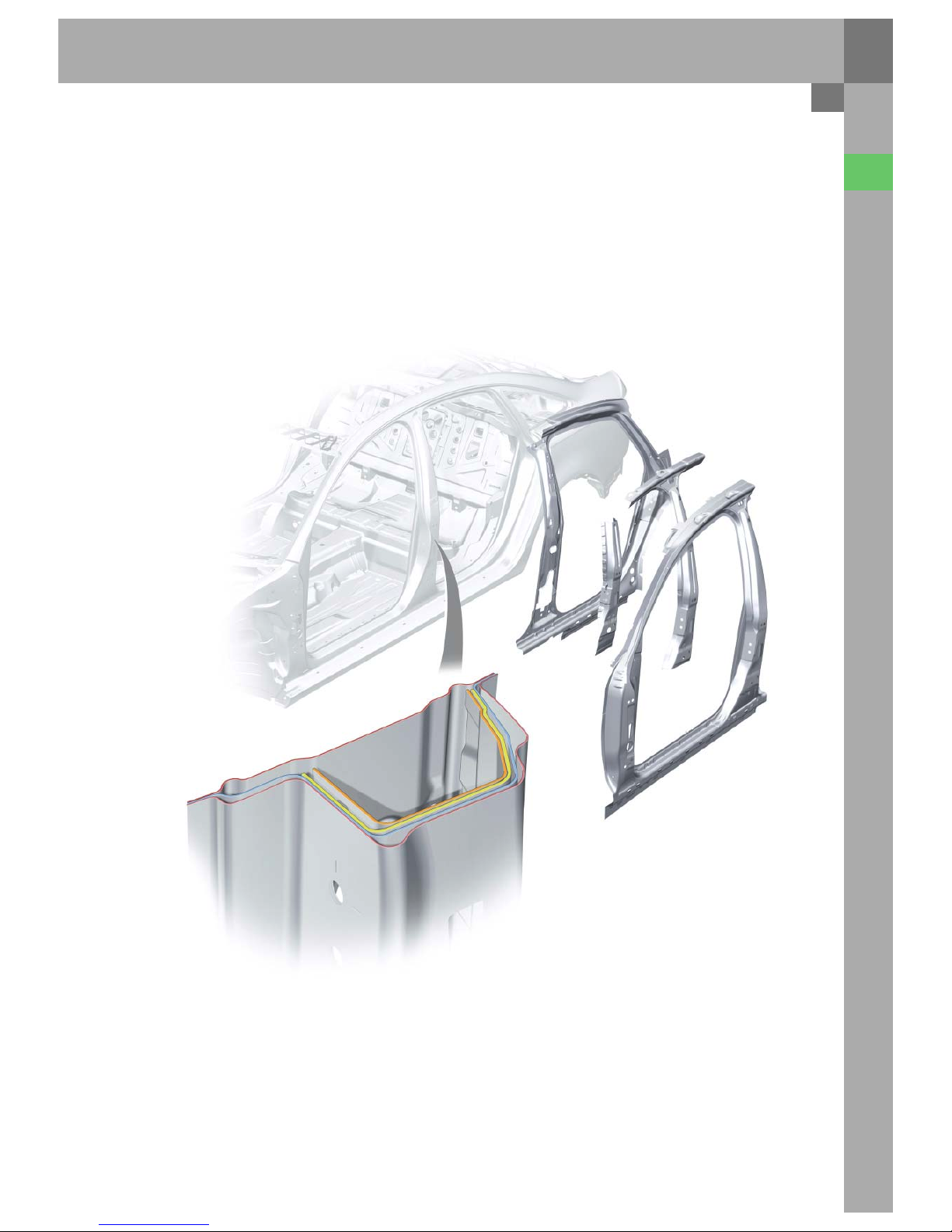
In addition to classic resistance spot welding, the
following connecting techniques are used on the
new A6´05 body shell:
– Spot welding bonding
– Punch riveting
– Clinching (bonnet & rear opening hood)
– Laser soldering
– Laser welding
– as well as MIG soldering
Spot welding bonding, using a high-strength
structural adhesive, is used for particularly
crash-relevant and rigidity determining connections
(length of the bonded seam factor 3 compared with
predecessor).
Spot welding bonding
Laser
323_002
MIG soldering
The Aluminium components are joined to the
galvanized steel sheets by means of punch rivets
and by bonding.
The roof and side panel frame are joined by
laser-soldering.
Poorly accessible components are joined by
laser-welding.
The laser-welding head is smaller and thus has
greater flexibility than comparable spot welding
tongs.
In addition, the weight can be reduced by reducing
the flange widths.
MIG soldering is used for closed sectional bars
which are only accessible from one side,
e.g. longitudinal floor members.
323_003
Roof
Laser-soldered zero joint
Outer side part
These aluminium-steel connections are used on the
following parts in the body:
– in the plenum chamber front panel
– sill reinforcement (with aluminium extruded
section)
– rigid rear panel with rear shelf
10
Body
High tensile steels (180 - 300 N/mm²)
Dual-phase steels (340 - 500 N/mm²)
Weight percentage of high-tensile steel sheets
To ta l : 4 5 %
Upper section: 42.3 %
Lower section: 46.7 %
Special steel (600 - 900 N/mm²)
Aluminium
Hybrid co mponent
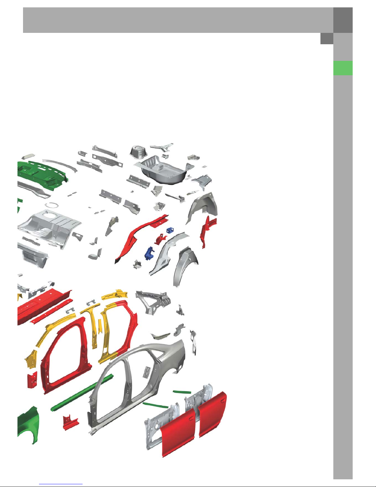
Materials
In addition to conventional deep-drawing steels, the
following materials are used in the body structure
of the new Audi A6´05:
– High tensile sheet steel
– Special sheet steel
– Aluminium sheets
– Aluminium extruded sections and
– Plastic-ribbed deep-drawing steel component
(hybrid component)
11
Large-volume aluminium extruded sections are
used as sill reinforcements to stiffen the cell
structure in the event of an offset or side crash.
The front roof frame is designed as a hybrid
component in order to reduce the weight.
323_004
High-tensile steel sheets are used especially in
areas which require strengthening and greater
impact resistance.
Special steel sheets are also used in the body
structure, e.g. front wheelhouse cross-member.
The engine bonnet and front mudguards are made
of aluminium.
In addition to the add-on parts in the shell,
aluminium sheets are used in the structure for
large-area components which are not subject to
excessive stress.
12
Body
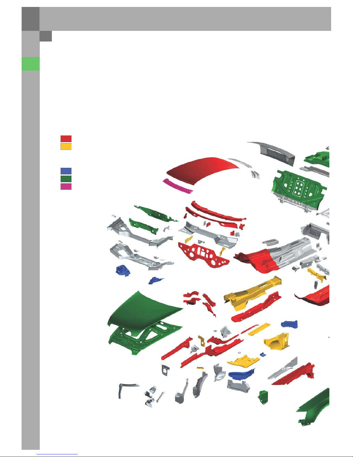
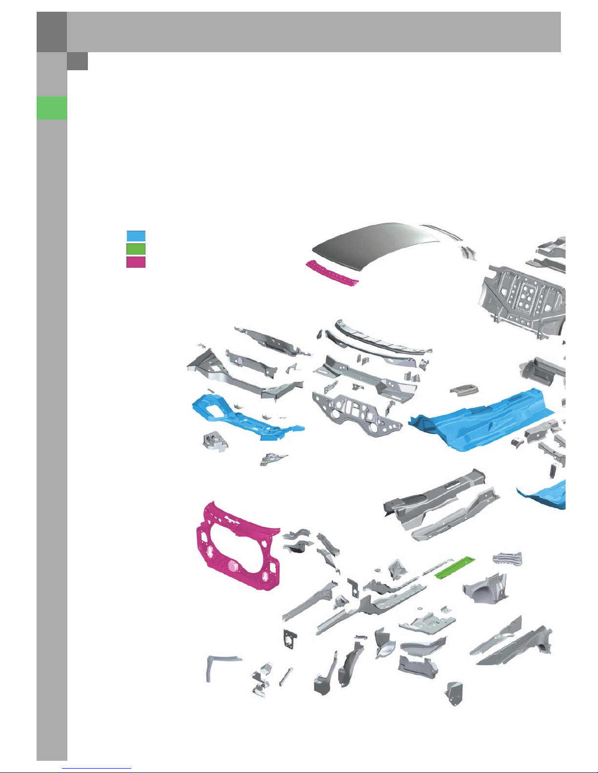
Blanks
Blanks with different wall thicknesses and material
qualities are used to realize a stress-adapted
material distribution for large-area components
which are subject to high stress.
tailored blanks
tailored-rolled-blanks
hybrid components
Laser-welded blanks, so-called tailored-blanks,
are used for
– the front suspension strut cross member
– front floor panels
– inner side section
– rear longitudinal member
– and door inner panels
13
Tailored-rolled blanks, which have variable rolled
wall thicknesses, have particular advantages.
They can be used to produce continuous material
thickness transitions which meet the local stress
conditions. This technique is used to optimize the
front longitudinal member structure.
In total, a weight reduction of 8 kg (without add-on
parts) was realized through the material selection
being adapted to the respective stress conditions.
An additional weight reduction of 9 kg was realized
by using blanks with different wall thicknesses.
323_005
14
Body
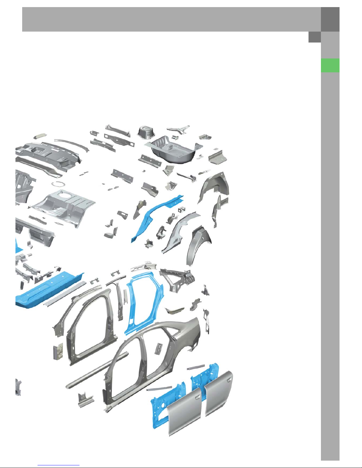
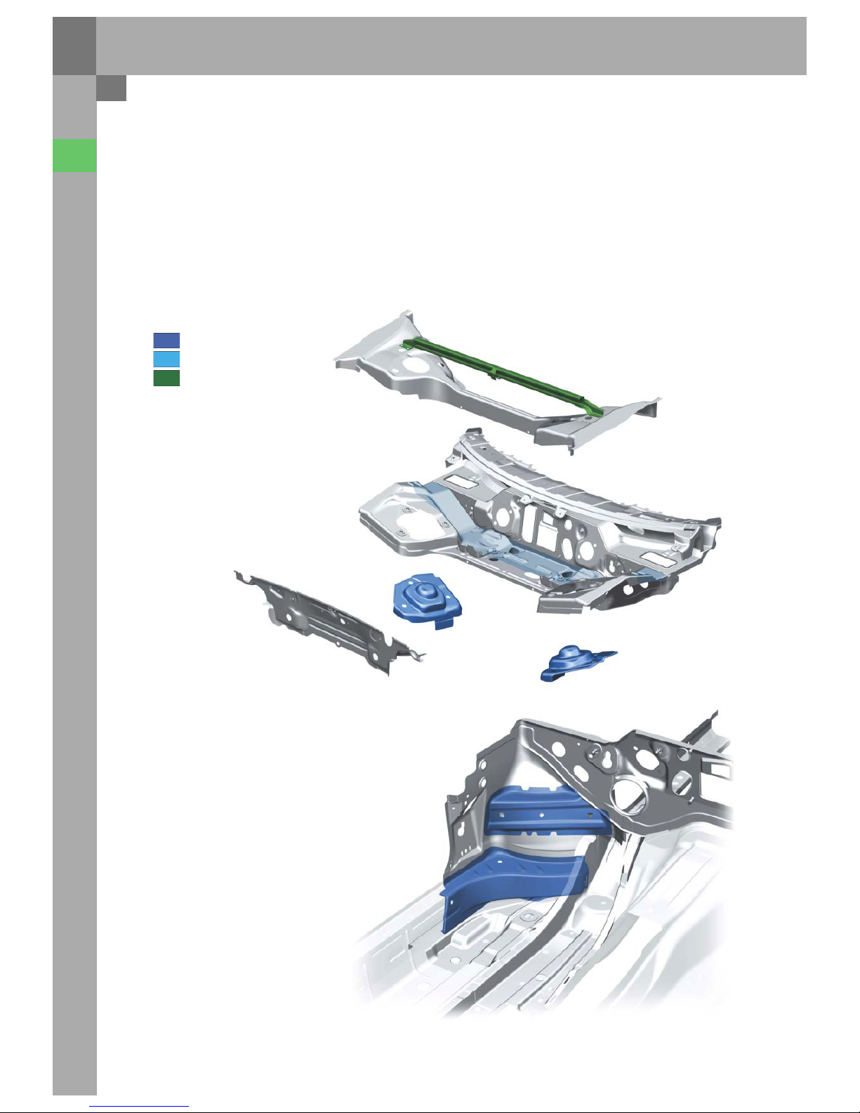
Assemblies
Plenum chamber
One application area for special steel is the chassis
connection in the proximity of the spring and shock
absorber seat.
It was possible to reduce the wall thickness of the
respective parts from 2.5 to 1.4 mm.
The resulting loss of local rigidity was offset by
creating an optimized profile.
323_031
Special steel (600 - 900 N/mm²)
tailored blanks
Aluminium
In addition, a tailored blank is fitted in the plenum
chamber.
This ensures the highest possible energy
absorption in the event of a crash.
At the same time, the necessary rigidity and
stability are ensured during normal driving.
Transverse rigidity is ensured by a rolled sectional
bar as an additional reinforcement.
323_030
Wheelhouse
To ensure an optimum introduction of the crash
energy from the front of the car into the passenger
compartment, special steel components were used
in the proximity of the wheelhouse.
15
323_032
B-pillar
Due to the increased requirements regarding the
strength of the B-pillar, a combination of different
materials is used.
– front inner side section (high tensile steels)
– rear inner side section, tailored blank
(dual-phase steels, high tensile steels)
t = 1.35 mm and 0.8 mm
– B-pillar reinforcement (dual-phase steels)
– B-pillar (dual-phase steels)
16
Body
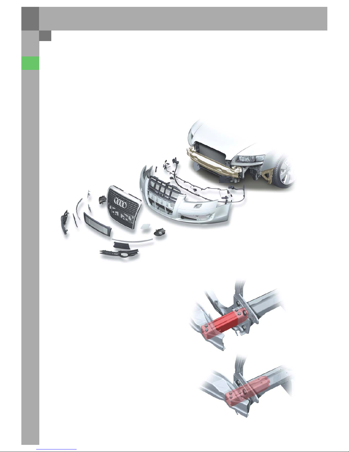
323_006
The bumper support comprises an open aluminium
cross member, which is screwed on to the
longitudinal member using newly developed shear
boxes.
The shear box absorbs the crash energy from all
centrical and slightly diagonal impacts through its
shearing effect.
Expensive damage to the welded vehicle structure
behind it is thus avoided up to a speed of 15 km/h.
In the event of diagonal impacts, the impact energy
is absorbed by the bumper buckling (folding) and
deforming.
The seat for the towing lug is integrated in the
right-hand shear box.
The towing forces are guided centrically into the
longitudinal member.
323_008
The number plate in the radiator grille is integrated
stylishly and harmoniously within the overall
design.
Bumpers
Front bumper
The bumper on the new Audi A6´05 is painted in the
colour of the car.
It comprises the following components:
– Coating
– Top cover
– Towing lug cover
– Radiator grille with chrome frame
– Fog lamps
– Side air inlet grilles
– Bumper support
17
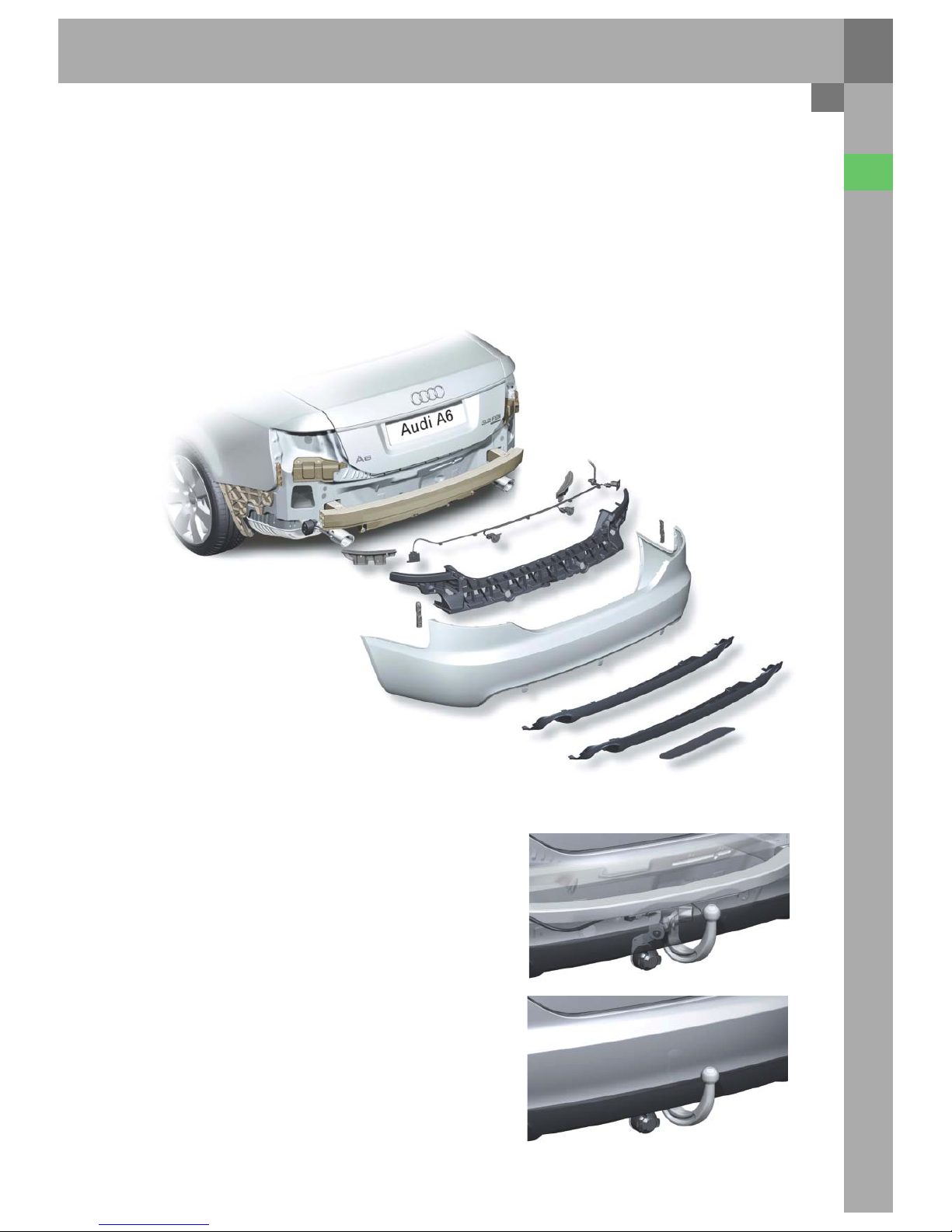
Rear bumper
The rear bumper assembly comprises the coating,
spoiler, towing lug cover and closing part
components. It is mounted on the vehicle by means
of fixed guides on the body. The bumper support
and the bracket for the bumper support are made of
aluminium and are produced by extrusion
moulding.
Trailer coupling
The newly developed trailer coupling fitted in
the A6´05 is equipped with a mechanically
swivelling ball rod.
The ball rod swivels around a rotation axis, which is
angled at 45° to the longitudinal axis of the vehicle.
The swivel angle between the swivelled-out towing
position and the idle position behind the bumper
is 180°.
The system is unlocked by means of a handwheel
located in the boot.
323_007
Compared to the previous model, the joints on
the A6´05 have been noticeably reduced.
Due to a special adjusting/holding part below the
rear light, the zero joint between the bumper
coating and side part has been reduced to 0.8 mm.
A parking aid and a mechanically swivelling trailer
coupling are available (optional).
323_010
323_009
18
Body
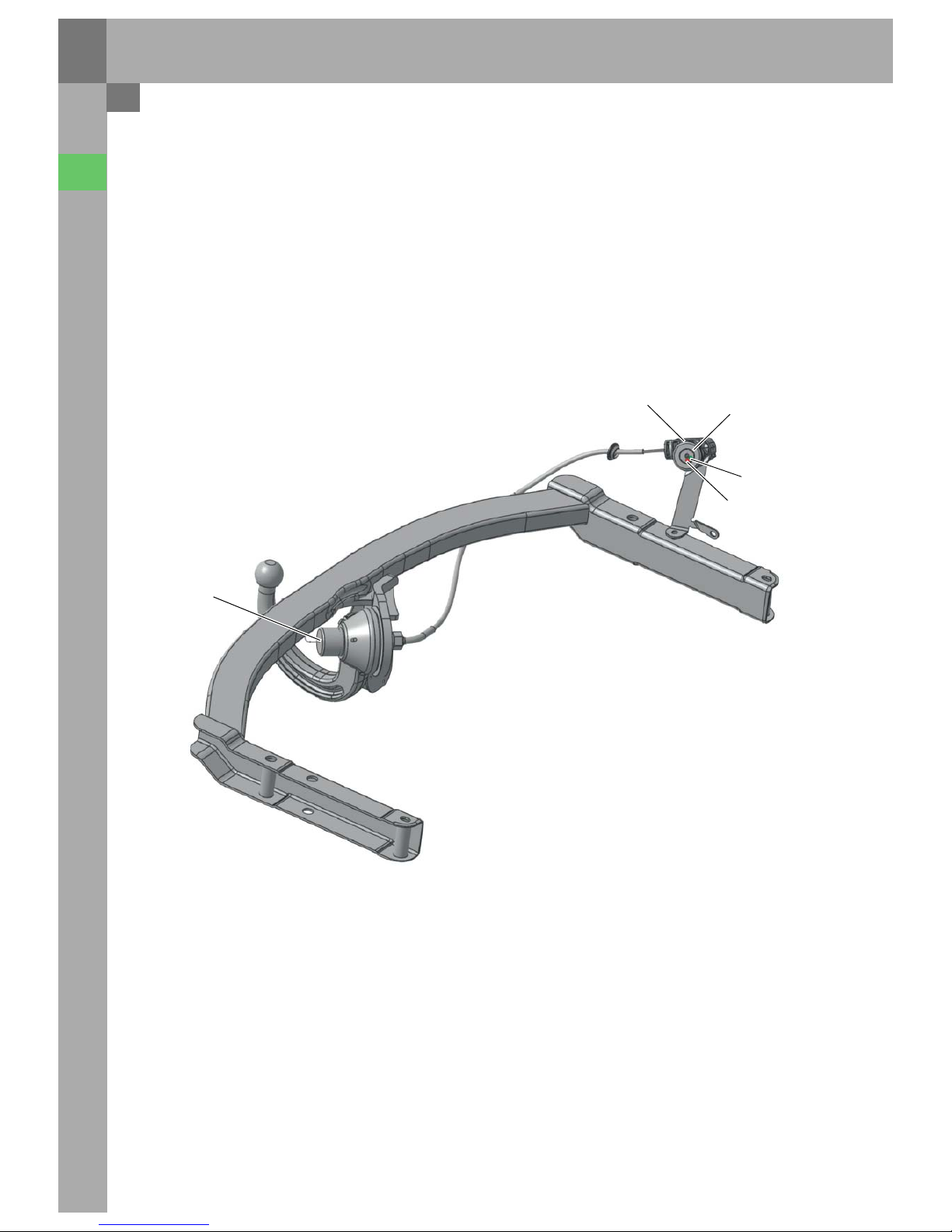
Control unit for trailer detection J345
Arrangement in the vehicle
The basic function of trailer detector control
unit J345 corresponds to the control unit which has
already been in use since the 2001 Audi A4.
To be used in the Audi A6´05, it was upgraded by the
control function for the swivelling trailer coupling.
It now has the additional task of detecting the
locking status of the mechanically swivelling trailer
coupling and indicating this to the driver.
323_035
F354
K226
K227
Handwheel
F355

19
On pulling the handwheel in the boot, the contact
switch on handwheel F354 is closed. On turning the
handwheel, the locking bolt on the trailer coupling
is unlocked mechanically by a Bowden cable and
the contact switch on locking bolt F355 opens.
After being unlocked, the trailer coupling can be
swivelled out/in mechanically. After being swivelled,
it is automatically locked by spring power. The
contact switches return to their initial position.
The control unit cannot differentiate between a
locked, swivelled-in trailer coupling and a locked,
swivelled-out trailer coupling.
The locking state is indicated by two LEDs in the
handwheel for the trailer coupling. When the green
warning lamp for trailer coupling locked (K226)
lights up continuously, it indicates that the trailer
coupling is swivelled in/out correctly.
323_036
323_033
CHECK
TRAILER
COUPLING
The red warning lamp for trailer coupling
unlocked (K227) flashes when the trailer coupling is
not locked. In addition, a message appears on the
central display in dash panel insert J285.
When terminal 15 is switched off, the warning lamp
for trailer coupling locked (K226) switches off if the
tailgate/boot lid is closed or remains open for
longer than 10 minutes. The warning lamp for trailer
coupling unlocked (K227) switches off if the tailgate/
boot lid is closed or remains open for longer than
20 minutes. The respective warning lamp switches
on again when there is a control unit wake-up or a
CAN wake-up.

20
Passenger protection
Safety system
A top-level safety system: The performance target is
to increase the existing high safety level of the
current Audi fleet.
The compliance with current laws and the
completion User tests, in which the new
Audi A6´05 was to gain a top position in the rating
scheme, were only a part of the extensive safety
requirements. In many cases, additional Audi
in-house requirements increase the requirements
which have to be met by the development team.
Particular attention was paid to a high protection
potential in the event of an accident and the
compatibility. Audis's policy of designing vehicles
with high safety specifications is supplemented
by scientifically gained knowledge of the
actual accident and its effects.
For this, the AARU (Audi Accident Research Unit*)
examines crashes involving relatively new
Audi vehicles.
The development team's task is to analyse and
reconstruct accidents and to draw up potential
improvements.
In addition to this, the AARU evaluates the relevant
accident databases.
The safety system in the Audi A6´05 comprises the
following familiar components:
– Airbag control unit
– Driver and front passenger airbags, two-stage
– Front side airbags
– Sideguards (head airbags)
– Sensors for side crash detection
– Front belt tensioners
The Audi A6´05 has the following new components:
– Crash sensors for the front airbag, the so-called
upfront sensors for frontal crash detection
– Battery cut-off relay
– Sensors for side crash detection in the doors
– Switches in the front belt locks
– Seat occupied recognition in the front passenger
seat
The vehicle can be equipped with side airbags at the
rear and a key switch for deactivating the front
passenger airbag with a corresponding warning
lamp (optional).
The safety system in the Audi A6´05 is rounded off
by the active head restraints in the front seats.
The A6´05 thus constitutes a successful example of
an overall vehicle development aimed at protecting
the passengers.
Due to the different demands and legal
provisions which car makers are subject to in
the different markets, the equipment can vary for
the US American market in particular.
* Audi Accident Research Unit
Note
Observe the respective safety instructions
in the repair guide before carrying out
any work on the airbag system!
Legend
E224 Airbag disabling key switch, front passenger side
E24 Belt switch, driver side
E25 Belt switch, front passenger side
G128 Seat occupied sensor, front passenger side
G179 Crash sensor for side airbag, driver side (front door)
G180 Crash sensor for side airbag, front passenger side
(front door)
G256 Crash sensor for side airbag, rear, driver side
G257 Crash sensor for side airbag, rear, front passenger side
G283 Crash sensor for front airbag, driver side
G284 Crash sensor for front airbag, front passenger side
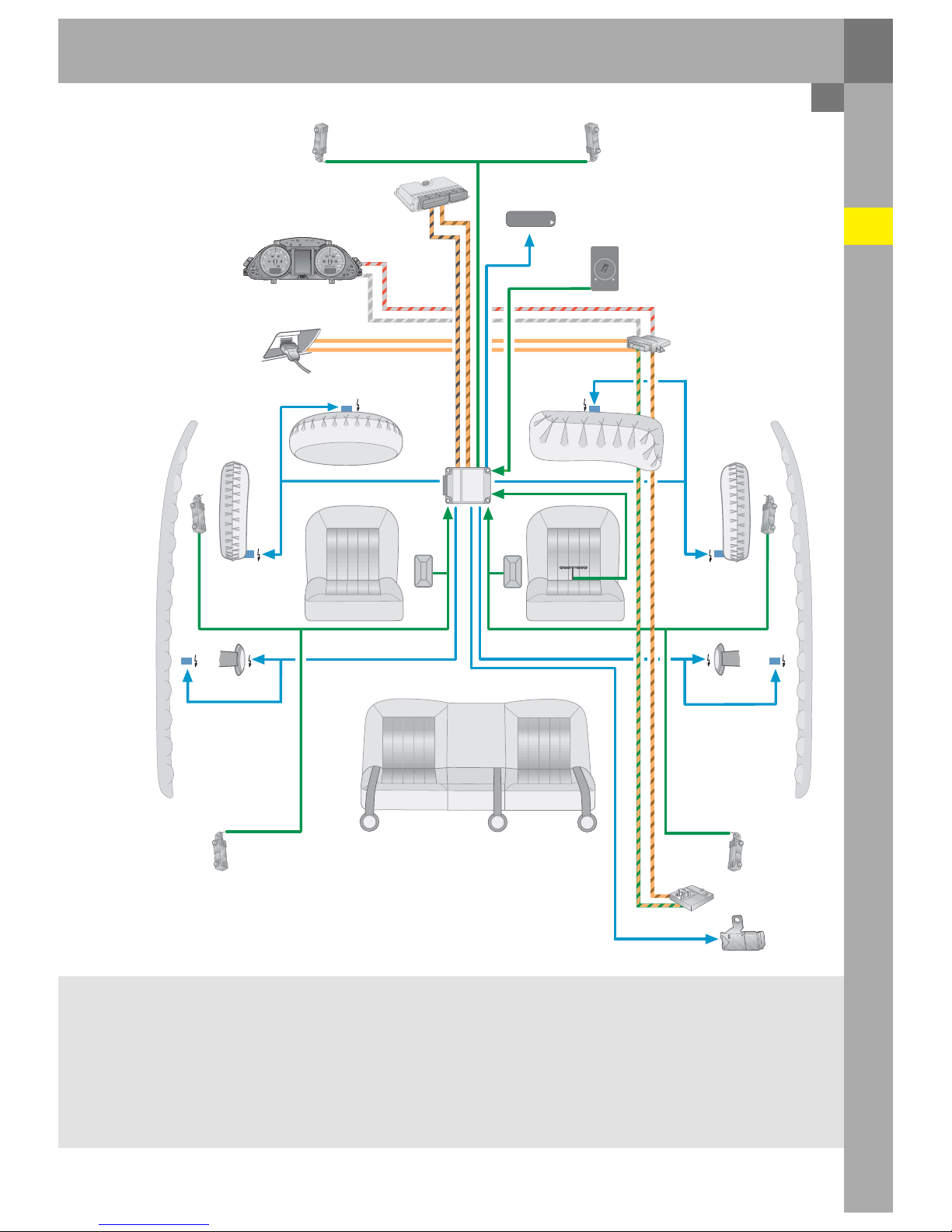
21
G256
N251
G179
G180
N153
K14 5
AIRBAG OFF
PASSENGER
N95 / N250 N131 / N132
N252
N154
G257
J5 33
G283
G284
N200
T16
J623
J285
K75 / K19
E224
AUS
EIN
AIRBAG
J655
E24 E25
J2 34
J3 93
N199
G128
326_002
N95 Airbag igniter, driver side
N250 Airbag igniter 2, dr iver side
N131 Airbag igniter 1, front passenger side
N132 Airbag igniter 2, front passenger side
N153 Belt tens ioner ign iter 1, driver side
N154 Belt tensioner igniter 1, front passenger side
N199 Side airbag igniter, driver side
N200 Side airbag igniter, front passenger side
N251 Head airbag igniter, driver side
N252 Head airbag igniter, front passenger side
T16 Plug-in connection, 16x (diagnosis connection)
J234 Airbag control unit
J285 Control unit in dash panel insert
J393 Central control unit for convenience system
J533 Data bus diagnosis interface
J623 Engine control unit
J655 Battery cut-off relay
K19 Warning lamp for belt warning
K75 Airbag warning lamp
K145 Airbag warning lamp, front passenger side, off
(PASSENGER AIRBAG OFF)
22
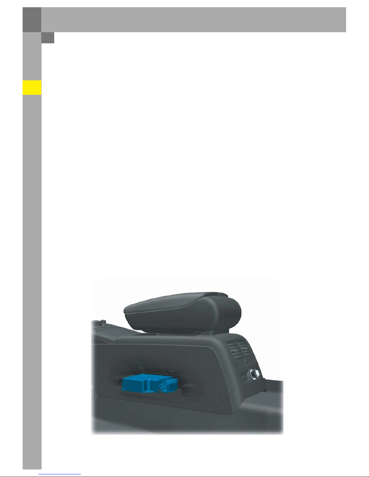
Airbag control unit J234
The task of the airbag electronics is to detect vehicle
deceleration and evaluate it so that a collision is
reliably detected. The control unit can detect
frontal, side and tail accidents. In addition, the
electronics also have the task of activating the
respective restraint systems (airbags / belt
tensioners) depending on the type of collision and
its severity and activating the Crash output.
The airbag electronics have the following main
tasks:
– Crash detection (front, side, tail)
– Defined triggering of the airbags, belt tensioners
and battery cut-off
– Defined triggering of the second front airbag
stage
– Evaluation of all input information
– Permanent monitoring of the entire airbag
system
– Independent power supply via capacitor for a
defined time (approx. 150 ms)
– Error indication via failure warning lamp
– Storage of error and crash information
– Notification of a crash event to other system
components via drive CAN or discrete
Crash output (conventional cabling)
– Activate belt warning
In addition to the internal sensors in the control
unit, the external crash sensors are also used to
detect vehicle deceleration during impact.
The electronics can only decide when and which
safety components to activate after all the sensor
information has been evaluated by the control unit
electronics.
If an airbag control unit is replaced, then it must be
coded and adapted to the respective.
These functions can only be peformed by means of
the guided fault finding procedure and a diagnosis
tester which can be used online. The Service
technician needs access (with password) to the
”FAZIT” database at Audi.
If the coding or adaptation is not carried out in the
correct manner, malfunctions can occur in other
vehicle systems such as the ESP, for example.
Passenger protection
326_008

23
Airbag warning lamp K75
The airbag warning lamp, which is located in
dash panel insert J285, is triggered via the bus CAN.
If there is no data message from the airbag control
unit, the warning lamp is automatically switched on
from the dash panel insert.
Rear crash detection
In the event of a rear-end crash, the airbag control
unit evaluates the information from the internal
crash sensor and the crash sensors for front
airbags G283 and G284. If their signals exceed a
fixed value, the belt tensioners are ignited and
the battery cut-off relay is activated.
Data exchange
The airbag control unit is integrated within the
drive CAN.
The airbag control unit transmits the following
information on the drive CAN:
– Trigger warning lamp K75
– Activate belt warning
– Diagnosis data
– Crash signal
– Crash information for the actuator test
– ESP data
– Front passenger airbag disabled (for USA only)
The airbag control unit evaluates the following
information from the data bus:
– Dimming of the airbag warning light
Passenger airbag off
 Loading...