

Page 1
Please also read
Part 1 — Important
Product Information
USER’S MANUAL
Par t 2
© 2004 Advanced American Telephones. All Rights Reserved.
AT&T and the Globe Design are trademarks of AT&T Corp., licensed to Advanced American Telephones.
REVISED 03/31/04
Four-Line Intercom
Speakerphone 974
974_CIB_1ATT_033104 3/31/2004 5:28 PM Page II
Page 2

© 2004 Advanced American Telephones.
All Rights Reserved.
AT&T and the Globe Design are
trademarks of AT&T Corp., licensed to
Advanced American Telephones.
Printed in Singapore. Issue 1AT&T 04/04
In case of difficulty, visit our Service Center at
www.telephones.att.com or call 1 800 222–3111.
974_CIB_1ATT_033104 3/31/2004 5:28 PM Page III
Page 3

974_CIB_1ATT_033104 3/31/2004 5:28 PM Page IV
Page 4

PRODUCT OVERVIEW............. 1
BEFORE YOU BEGIN.................. 2
Parts List ................................................ 2
Tools Needed ....................................... 2
DSL Users.............................................. 4
Glossary ................................................. 5
Programmable Features List............. 7
Audible Signals ................................... 10
INSTALLATION........................... 11
Battery Installation............................ 11
Table/Desk Installation..................... 13
Wall Installation................................. 15
Convenience Ports ........................... 19
MENU OPERATION.................. 20
Menu Structure.................................. 21
Shortcut to Language Menu........... 22
Rapid Scroll......................................... 22
FEATURE SETUP........................ 23
Set One Touch Preference.............. 23
Assign an Extension Number
to Your Phone ................................ 24
Turn the Ringer On or Off
for Each Line .................................. 25
Select the Ringer Type ..................... 26
Set Delay Ring.................................... 27
Turn Auto-Mute On or Off............ 28
Set Dial Mode .................................... 29
Turn Hold Reminder On or Off ... 29
Set the Time and Date..................... 30
Turn Line Usage On or Off for
Each Line ......................................... 31
Assign the Prime Line
(Line Preference)........................... 32
Set Automatic Mode......................... 33
Set the Scroll Rate............................ 34
Turn Screen Backlight
On or Off........................................ 35
Turn COVM Indicators
On or Off for Each Line............. 36
Reset COVM Indicator.................... 37
Program Home and Local
Area Codes .................................... 38
Assign the Line Group
for this Phone ................................ 39
Erase All Settings and Return
the Phone to Default Settings... 40
Set This Phone to be the
Centrex Console Phone............. 41
Set the Centrex Console
Delayed Ring Time........................ 42
Set the Display Language................. 42
TELEPHONE OPERATION... 43
Make or Answer a Call.................... 43
Switch Between Handset,
Headset and Speakerphone ....... 45
Timer.................................................... 45
Call Privacy.......................................... 46
Do Not Disturb ................................ 46
Volume ................................................. 47
Redial.................................................... 47
Redial Stack......................................... 48
Auto Redial......................................... 48
Hold ...................................................... 49
Switch Between Lines...................... 49
Mute...................................................... 50
Flash ...................................................... 50
Temporary Tone Dialing .................. 50
Conference Calls............................... 51
Transfer a Call.................................... 52
Low Battery Indicator...................... 53
Lights and What They Mean ........... 54
ONE TOUCH OPERATION .. 55
Store a Number in a
One Touch Location..................... 56
Review a One Touch Entry............. 58
Dial a One Touch Number............. 59
DIRECTORY OPERATION .... 60
Menu Structure.................................. 60
Store a Name and Number
in the Directory ............................ 61
Review Directory Entries ............... 64
Edit a Directory Entry ..................... 65
Dial a Number from
the Directory................................. 66
i
CONTENTS
CONTENTS
CONTENTS
974_CIB_1ATT_033104 3/31/2004 5:28 PM Page i
Page 5

DIRECTORY OPERATION
continued
Remove a Name and Number
from the Directory ...................... 66
Remove All Entries from
the Directory................................. 66
INTERCOM OPERATION...... 67
Basic Intercom Operations ............ 68
Make an Intercom Call with
the Handset.................................... 69
Make an Intercom Call with the
Speakerphone or Headset.......... 70
Answer an Intercom Call................ 71
End an Intercom or Page Call ....... 71
Page a Specific Extension
(Single-phone Page)...................... 72
Answer a Single-phone Page.......... 72
Page All System Phones................... 73
Answer a System-wide Page.......... 73
Make an Intercom
Conference Call............................ 74
Room Monitor................................... 74
CALLER ID OPERATION....... 75
Caller ID Display............................... 76
Call Waiting......................................... 76
Calls Received on Two or
More Lines Simultaneously......... 77
Display Screen Messages................. 78
Message Waiting and
NEW CALL Light ......................... 79
Call History ........................................ 79
Remove Calls from
Call History .................................... 81
Dial a Number from
Call History .................................... 82
Save a Name and Number from
Call History to the Directory... 83
Save a Number from Call History
to a One Touch Location............ 84
ADDING A FAX MACHINE.. 85
Using a Fax Switch............................ 85
GENERAL PRODUCT
CARE .................................................. 86
TECHNICAL
SPECIFICATIONS....................... 87
IN CASE OF DIFFICULTY..... 88
EXPANDING THE
PHONE SYSTEM......................... 93
Line Groups........................................ 93
Private Lines ....................................... 94
CENTREX OPERATION......... 95
Setup Checklist.................................. 95
Enable the Console Phone ............. 95
Console Operation........................... 95
Set Ring Delay Duration ................. 96
Answer a Delayed Ring ................... 96
Pick Up Another Station’s Line...... 96
INDEX................................................ 97
ii
CONTENTS
CONTENTS
974_CIB_1ATT_033104 3/31/2004 5:28 PM Page ii
Page 6

This AT&T 974 Four-Line Intercom Speakerphone is expandable to a
16-extension telephone system. The 974 is compatible with AT&T 945, 984,
944, 955 and 964 telephones. (See BEFORE YOU BEGIN starting on page 2
and EXPANDING THE PHONE SYSTEM beginning on page 93 for details.)
The 974 is hearing-aid compatible and can be connected to up to four
incoming telephone lines. This phone features a speakerphone for hands-free
use and a headset jack compatible with most two-band 2.5mm headsets (sold
separately). The 974 allows paging, intercom and call transfers between
system phones and is capable of connecting three parties in a conference call.
This phone also features a 32-number memory for faster dialing and has a
directory which can store up to 200 additional numbers with names. This
phone has a Caller ID feature which supports Caller ID with Call Waiting
service. (Caller ID services are subscriber services available from many local
telephone companies for a fee.) There are two convenience ports available
for connecting the phone to another device such as a fax machine or modem.
The 974 is compatible with Centrex service. Centrex is a special subscriber
service which may be available from your local telephone company for a fee.
If you subscribe to Centrex service, refer to the CENTREX OPERATION
section of this manual, beginning on page 95.
This User's Manual contains detailed instructions for installing, programming
and operating your AT&T 974 Four-Line Speakerphone. Please be sure to
read BEFORE YOU BEGIN starting on page 2 before installing this phone.
1
PRODUCT OVERVIEW
PRODUCT OVERVIEW
PRODUCT OVERVIEW
974_CIB_1ATT_033104 3/31/2004 5:28 PM Page 1
Page 7
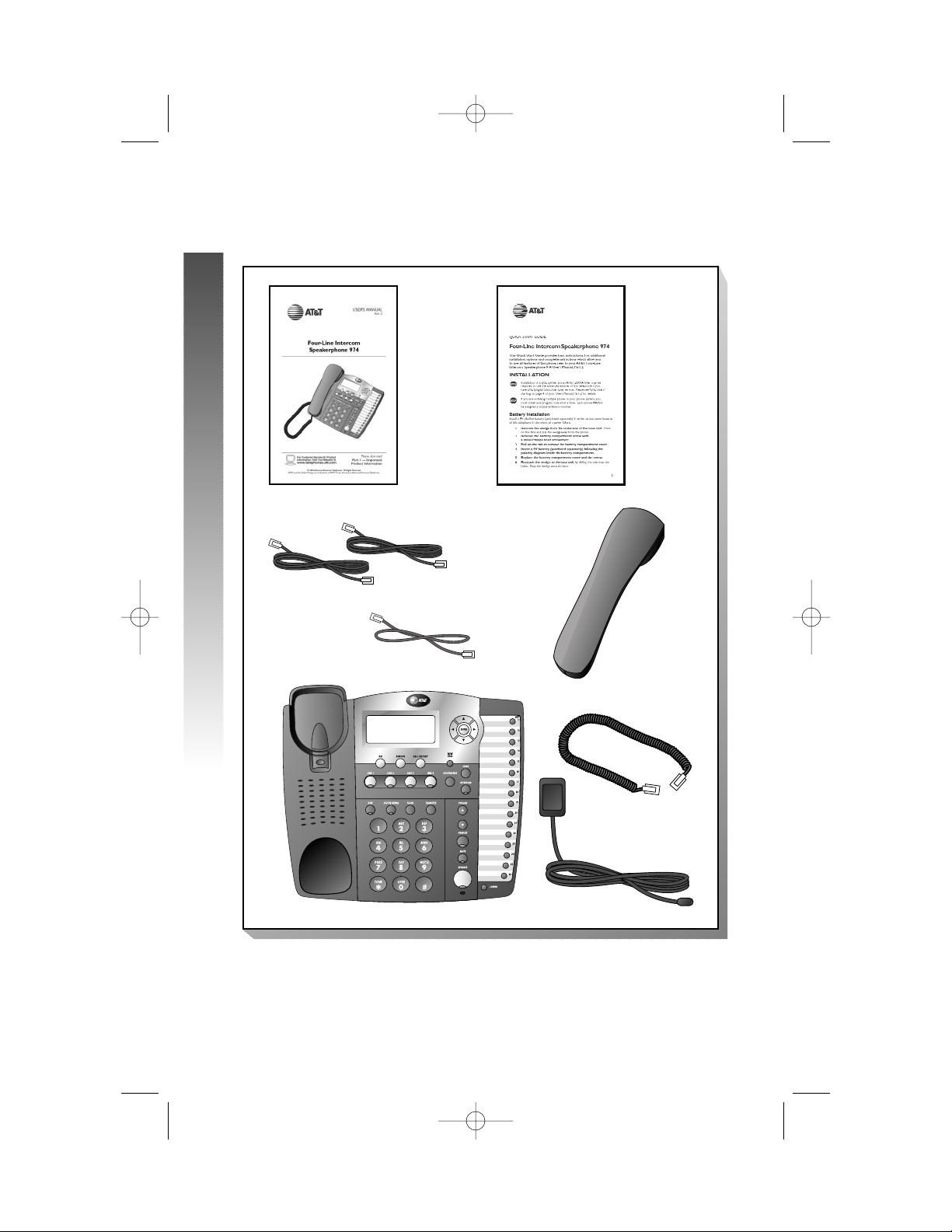
Parts List
Your box should include:
Tools Needed
You will also need a small Phillips head screw driver to install your phone.
2
BEFORE YOU BEGIN
BEFORE YOU BEGIN
BEFORE YOU BEGIN
Coiled
handset cord
Power adapter
Two seven-foot twisted pair
line cords
Handset
This User’s
Manual
Quick
Start
Guide
Base unit with wedge attached
Eight-inch line cord
974_CIB_1ATT_033104 3/31/2004 5:28 PM Page 2
Page 8

This 974 telephone is fully compatible with any AT&T Four-Line Intercom
Speakerphone 945 or 984 units you may have installed. You can use a total
of 16 945/974/984 units together as extensions in your phone system.
This 974 telephone is also compatible with any AT&T 964/955/944 phones
you have previously installed. This 974 telephone is NOT compatible with
any 843, 853, 854, 874, or 954 telephones you may have previously installed.
¥
NOTE: If you have one or more 964, 955, or 944 phone(s) installed in
the same phone system with this 974 telephone, you can have only 12
extensions and 15 telephone lines in the phone system.
• You must have a modular telephone jack and an electrical outlet not
controlled by a wall switch near where you’re installing the phone.
The total length of telephone wiring used in this system MUST
NOT be more than 600 feet. In some cases a Z800A filter can
be used in a phone system with more than 600 feet of wire.
AT&T highly recommends that a Z800A filter be installed
by a professional. AT&T CANNOT guarantee that this
telephone will work with such a filter, and IS NOT
responsible for the cost of such installations or for
arranging the installation. A Z800A filter can be obtained
by calling 1 800 222-3111.
• Identify the number of phone lines you’ll use.
• Plan the layout of your phone system.
• All connected phones must have the same Line 1 phone number for
the Intercom and Page features to work.
Every individual phone in your telephone system MUST be assigned
a unique extension number for the Intercom feature to work. If you
try to assign the same extension number to a second phone, you
will hear a repeating short ring and the the screen display will
include EXT XX is already used Assign new EXT #.See
“Assign an Extension Number to Your Phone” on page 24 of this
manual for directions.
• Decide if you want a private line. A private line does not appear on
all connected phones.
• Choose your setting for each feature. You will need to program
the features after installation. See “Programmable Features List”
beginning on page 7 for a brief description of the features. See the
FEATURE SETUP section beginning on page 23 for programming
instructions.
3
BEFORE YOU BEGIN
BEFORE YOU BEGIN
974_CIB_1ATT_033104 3/31/2004 5:28 PM Page 3
Page 9

DSL Users
Installation of a DSL splitter and an AT&T Z800A filter is required
to use the advanced features of this telephone if you have DSL
(Digital Subscriber Line) service.
Set-Up for DSL Users
If you are a DSL (Digital Subscriber Line) customer, you may experience
interference with the advanced features of this telephone. Certain features
of this phone (e.g., intercom, hold, line privacy, etc.) work by sending a data
signal using Line 1. This data signal is sent at some of the same frequencies
as those used by your DSL service. Microfilters are used to block the high
frequency DSL signals from being transmitted through and interfering with
your telephones. These same microfilters that may have been installed for
your DSL service will also block the data signals between your system
phones. Therefore, some features of this phone may not work properly
when DSL filters are installed in your building. This problem can occur even
if the DSL line is not one of the lines used by the phone system. If you use
the microfilters that your DSL service provider may have supplied when you
activated DSL service with this phone, some of the phone features will not
work. Once the DSL splitter (described below) is installed, you should no
longer experience interference.
Installation, by your DSL service provider or other professional, of a DSL
splitter (not a “microfilter”) AND an AT&T Z800A Isolation filter as close
as possible to the “protection block” or “network interface” (where the
telephone line enters the house) may resolve DSL interference. (It may be
necessary to use a DSL splitter intended for outdoor use.) A DSL splitter
allows the data and voice signals to use the same telephone line without
interfering with each other. An AT&T Z800A filter isolates the splitter from
your phone system and reduces interference with the signals used by the
system phones to communicate with each other.
You can obtain an AT&T Z800A filter at no charge by calling
1 800 222-3111. You will also receive a diagram showing the proper
installation of the AT&T Z800A filter with a DSL splitter, DSL modem and
your system phones. AT&T cannot supply the DSL splitter.
Please contact your DSL service provider or professional contractor for
details about obtaining and installing a DSL splitter. Your DSL service provider
may require you to bear any installation costs. AT&T and the manufacturer of
this product have no affiliation with your DSL provider and the type or quality
of services they offer. Installation must be performed at your own expense
and AT&T cannot troubleshoot or provide installation support.
4
BEFORE YOU BEGIN
BEFORE YOU BEGIN
974_CIB_1ATT_033104 3/31/2004 5:28 PM Page 4
Page 10

¥
NOTE: If your DSL service provider cannot supply a DSL splitter, it is
possible to purchase an outdoor DSL splitter (such as a Corning or Allen
Tel brand DSL splitter) over the Internet.
If you are a new DSL customer, your DSL service provider will likely ask you
if you have more than one telephone line in your home or business. If you
answer yes, your DSL service provider will probably advise you that you need
a splitter. Your DSL service provider may also ask if you are installing a phone
system. If you answer yes, your DSL service provider will most likely advise
you that you need a splitter. In most cases, your DSL service provider will
supply you with the proper splitter for your specific situation. The DSL
splitter, installed properly and in conjunction with a Z800A filter,should
help overcome any interference between the DSL signal and the signals
sent by your phone system.
AT&T shall not be responsible for the cost of installation, any damages, lost
business, direct or indirect expenses accrued or associated with installation,
or other compatibility issues which may arise as a result of using this product
while you subscribe to DSL service.
Glossary
Caller ID: Caller Identification is a subscriber service available from most local
telephone companies for a fee. When you subscribe to Caller Identification, you
can see who’s calling before you answer the phone if you and the caller are
both in areas offering Caller ID service with compatible equipment.
Caller ID with Call Waiting: This is a single, combined subscriber service
which may be available from your local telephone company. If you subscribe
to this service, you can use your 974 telephone to see who’s calling even
while you are on another call (as long as your caller is in an area with Caller
ID service and both telephone companies use compatible equipment).
Centrex Service: A special subscriber service which may be available
from your local telephone company for a fee. This 974 telephone can be
used with Centrex Service.
COVM: Central Office Voice Mail is a subscriber voice message service
which may be available from your local telephone company. This service may
be called by another name in your area (e.g., Call Answering).
DND: When activated, the Do Not Disturb (DND) feature prevents
interruptions during a call.
continued on page 6
5
BEFORE YOU BEGIN
BEFORE YOU BEGIN
974_CIB_1ATT_033104 3/31/2004 5:28 PM Page 5
Page 11

Glossary
continued from page 5
Home Area Code: This is the area code for your telephone number. Most
users simply dial the seven digits of a phone number to make a call within
their own area code and 11 digits outside of their area code. If this applies to
you, you should enter your own area code into the unit as the Home Area
Code. After programming, if you receive a call from within your Home Area
Code, the screen will display the seven digits of the phone number.
You may,however, live in a region where for calls within your own area code,
you must dial 10 digits (that is, the area code and phone number). If this
applies to you, enter “000” for the Home Area Code and enter your area
code as a Local Area Code. After programming, if you receive a call from
within your area code, the screen displays the 10 digits of the phone number.
Be sure to follow the directions under “Program Home and Local Area
Codes” on page 38 during Feature Setup.
Line Group: A group of system phones sharing some lines within a
multi-phone system.
Local Area Code: Most users dial 11 digits to make calls outside their
Home Area Codes. If this applies to you, you do not need to program any
Local Area Codes.
However, if you dial only 10 digits to make calls to some areas outside your
Home Area Code (without dialing “1”), then program these Local Area Codes
into the phone. Up to five Local Area Codes can be programmed. See
“Program Home and Local Area Codes” on page 38 during Feature Setup
for instructions.
After programming, if you receive a call from one of these Local Area Codes,
the screen displays the 10 digits of the phone number.
Navigation buttons: These are the buttons used when programming
your 974 phone and for scrolling through feature options (E, +,
-, >, <).
Phone System: Two or more system phones combined to form an
interacting system of shared lines. You can have up to 16 phones in
the system.
¥
NOTE: If you have one or more 964, 955, or 944 phone(s) installed in
the same phone system with this 974 telephone, you can have only 12
extensions in the phone system.
Prime Line: This is the line on your phone you designate to be selected
automatically when you lift the handset, press K, or press h.
System Phone: Any 944, 945, 955, 964, 974 or 984 phone in your phone
system (also called an extension).
6
BEFORE YOU BEGIN
BEFORE YOU BEGIN
974_CIB_1ATT_033104 3/31/2004 5:28 PM Page 6
Page 12

PROGRAMMABLE FEATURES LIST
Default settings indicated by *.
FEATURE: FUNCTION: OPTIONS:
ONE TOUCH Choose default mode Intercom* or Telephone
PREFERENCE for One Touch (EXT)
buttons.
EXTENSION NO Assign an extension 11*-26
number to this phone.
RINGER ON /OFF Turn the ringer on or On* or Off
off for each line.
RINGER TYPE Select a ring pattern Type 1*, 2, 3, 4
for this phone.
DELAY RING Select desired time Off*, 2, 4, 6, up to
to delay Central 30 seconds
Office ring.
AUTO-MUTE Turn Auto-Mute on On* or Off
or off (sounds at this
extension will be
heard automatically
when paged).
TONE/PULSE Set the dial mode for Tone* or Pulse
touch tone or dial
pulse (rotary) dialing.
HOLD REMINDER Turn on or off the On* or Off
audible reminder that
a call at this extension
is on hold.
TIME/DATE Set the time and date. 01:00 AM 01/01 Sunday*
LINE USAGE Turn Line Usage on On* or Off
or off for each line.
¥
NOTE: One ring is equal to about six seconds, two rings equals
twelve seconds, and so on.
continued on page 8
7
BEFORE YOU BEGIN
BEFORE YOU BEGIN
974_CIB_1ATT_033104 3/31/2004 5:28 PM Page 7
Page 13

Programmable Features List
continued from page 7
Default settings indicated by *.
FEATURE: FUNCTION: OPTIONS:
PRIME LINE Assign a line on this Line 1*, 2, 3, 4
phone to be selected
automatically when
you lift the handset,
press K,or
press h.
AUTOMATIC Choose default mode Speakerphone* or
MODE for calls connected Headset
with the handset in
the cradle.
SCROLL RATE Set the scrolling Very Slow, Slow, Medium*
speed for Rapid Fast, or Very Fast
Scroll.
LCD BACKLIGHT Turn the screen On* or Off
display backlight
on or off.
COVM ON/OFF Turn COVM (message/ On or Off*
voice mail) indicators
on or off for each line.
COVM RESET Clear COVM indicators N/A
when they are lit but
no new messages are
waiting.
AREA CODES Program one Home 1-3 digits, Empty*
and up to five Local
Area Codes for use
with Caller ID features.
LINE GROUP Assign your phone Line Group 4*-15 or
to a Line Group. PRV (private)
¥
NOTE: One ring is equal to about six seconds, two rings equals
twelve seconds, and so on.
8
BEFORE YOU BEGIN
BEFORE YOU BEGIN
974_CIB_1ATT_033104 3/31/2004 5:28 PM Page 8
Page 14

Default settings indicated by *.
FEATURE: FUNCTION: OPTIONS:
RESET ALL Return all features N/A
to default settings.
CONSOLE Specify whether your On or Off*
phone is the Centrex
Console phone for
your phone system.
CSL DELAY RING Set the time to delay Off*, 2, 4, 6, up to
ring for Centrex 30 seconds
Console phone.
LANGUAGE Select the language English*, Espanol, or
for screen displays. Français
¥
NOTE: One ring is equal to about six seconds, two rings equals
twelve seconds, and so on.
9
BEFORE YOU BEGIN
BEFORE YOU BEGIN
974_CIB_1ATT_033104 3/31/2004 5:28 PM Page 9
Page 15

Audible Signals
WHEN YOU HEAR: IT MEANS:
A RAPID DOUBLE-RING You have an incoming intercom call.
PATTERN, REPEATING
A LONG SINGLE RING, You have an incoming transferred call.
REPEATING
A SHORT SINGLE RING, The extension number you just
REPEATING programmed has already been assigned.
Choose another number
for this extension.
A SHORT SINGLE TONE, The extension you are calling is
REPEATING in DND mode.
A LONG SINGLE TONE, The extension you are calling is busy.
REPEATING
A VERY LONG SINGLE The extension you are calling is
TONE, REPEATING ringing.
10
BEFORE YOU BEGIN
BEFORE YOU BEGIN
974_CIB_1ATT_033104 3/31/2004 5:28 PM Page 10
Page 16
If you are installing multiple phones in your telephone system, you must
install and program one set at a time. If more than one extension
is assigned the same extension number, a repeating short ring (error
ring) sounds at the extension you are programming and the screen display
includes EXT XX is already used Assign new EXT #. Assign a
different extension number from 11 to 26 (see “Assign an Extension
Number to Your Phone” on page 24).
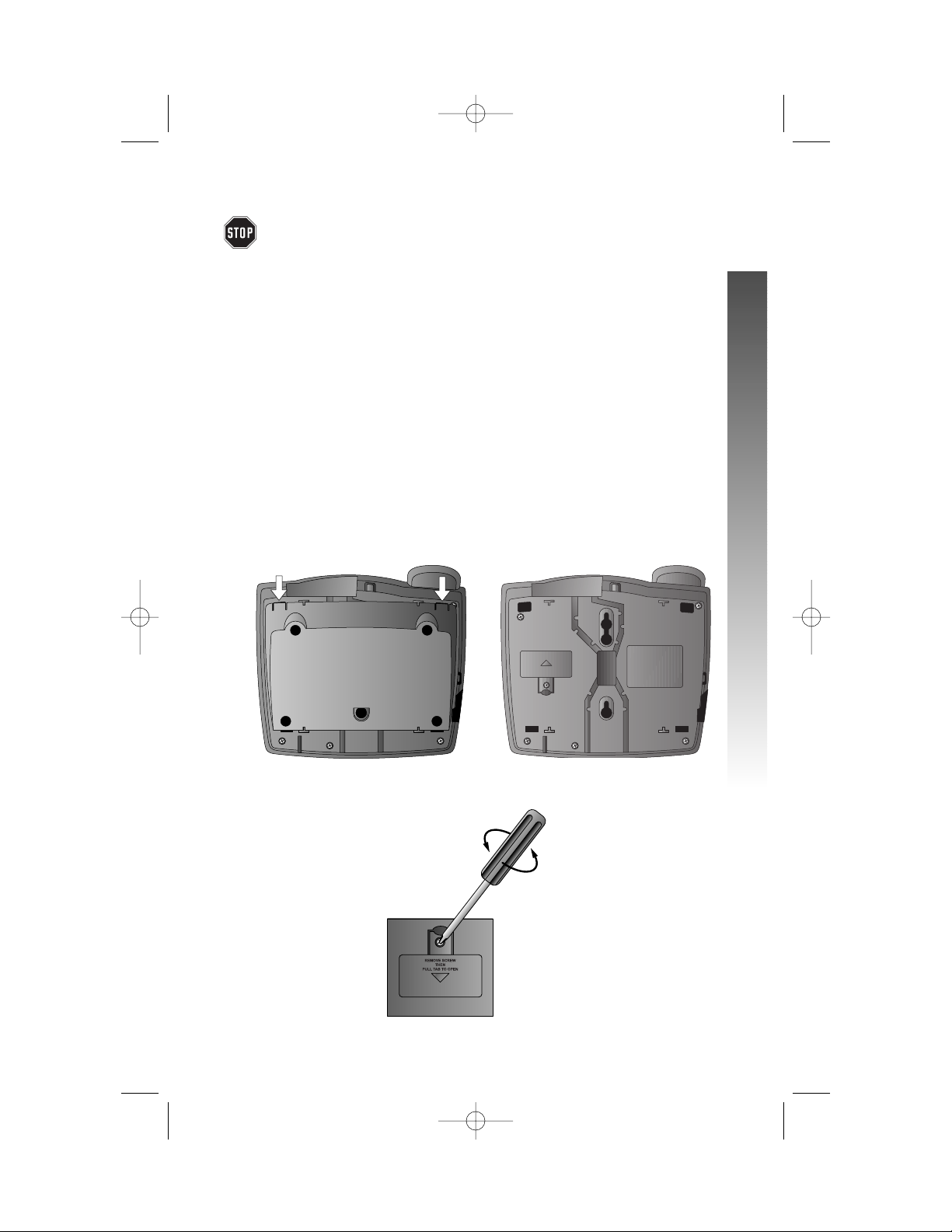
Battery Installation
Install a 9V alkaline battery (purchased separately) in order to use some
features of this telephone in the event of a power failure. If power fails and
a working battery is installed, all four lines of this phone will work only to
answer calls with the handset or headset, and to dial calls using the key pad
and the One Touch or Redial features. No other features will work until
power is restored.
1 Remove the wedge from the underside of the base unit.
Press on the tabs in the direction of the arrows and pull the wedge
away from the phone.
2 Remove the battery compartment screw with a small
Phillips head screwdriver.
continued on page 12
11
INSTALLATION
INSTALLATION
INSTALLATION
974_CIB_1ATT_033104 3/31/2004 5:28 PM Page 11
Page 17
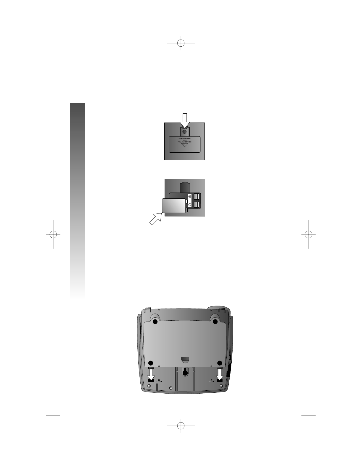
Battery Installation
continued from page 11
3 Pull on the tab to remove the battery compartment cover.
4 Insert a 9V battery (purchased separately).
5 Replace the battery compartment cover and the screw.
6 If you are wall mounting the phone, turn to “Wall Installation”
beginning on page 15. (You will not need the wedge; store it in case
you use the phone on a table or desk in the future.)
— OR —
If you are using the phone on a table or desk,reattach the
wedge to the base unit by sliding the tabs into the holes as shown.
Snap the wedge onto the base. Then, turn to “Table/Desk Installation”
beginning on page 13.
12
INSTALLATION
INSTALLATION
974_CIB_1ATT_033104 3/31/2004 5:28 PM Page 12
Page 18
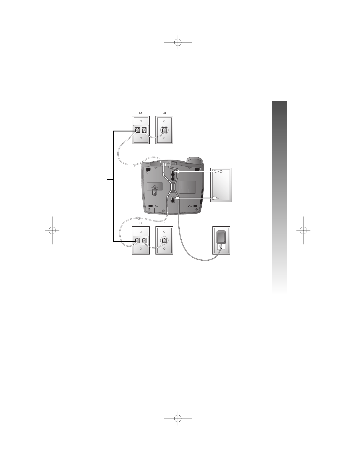
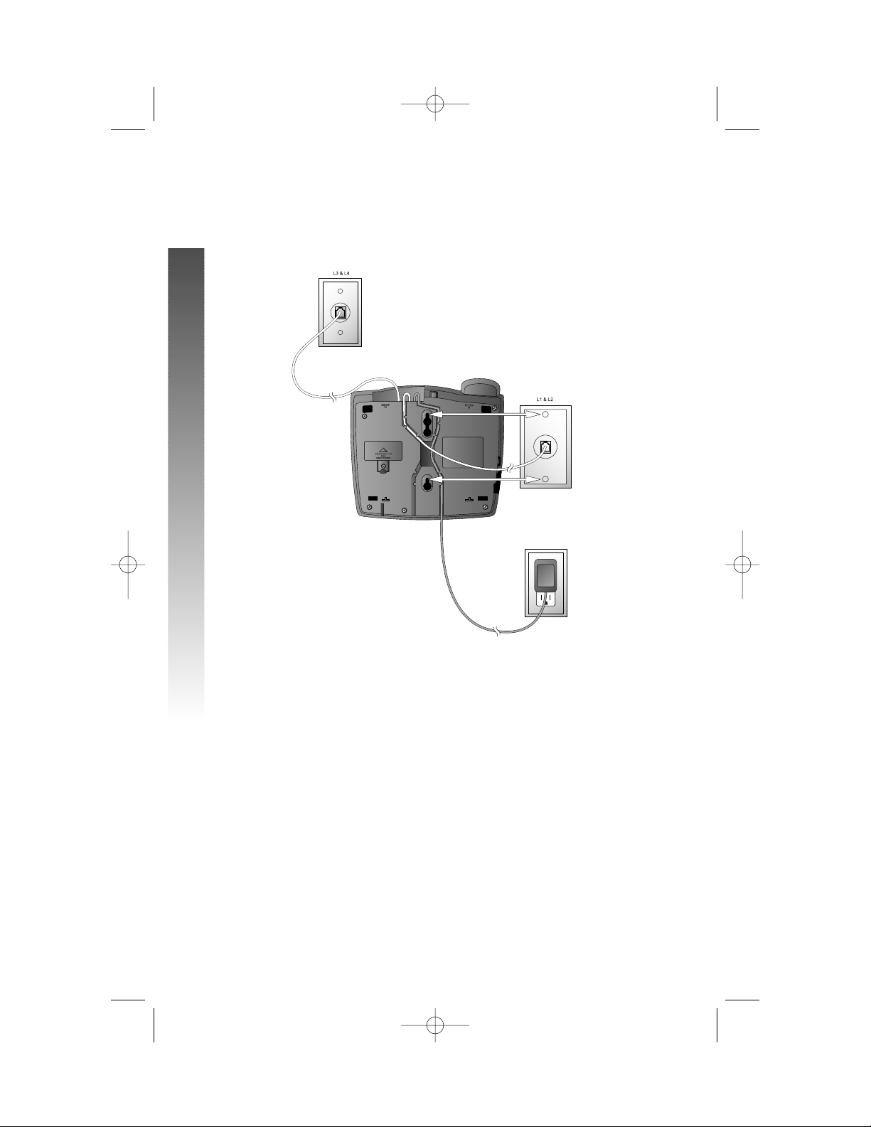
Table/Desk Installation
For best results, follow the directions in “Battery Installation” on page 11
before installing the phone.
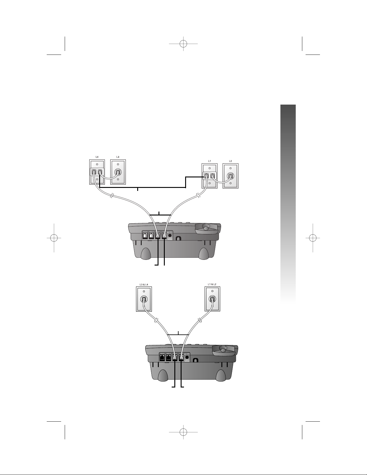
1 Connect the telephone line cords to the telephone and wall
jacks as shown in the appropriate illustration below. Use
only the line cords that came with this phone.
• Four One-Line Jacks (To use this installation option, you’ll
need to purchase two two-line adapters. Adapters are available
at retail stores or by calling 1 800 222–3111.)
• Two Two-Line Jacks
continued on page 14
13
INSTALLATION
INSTALLATION
Two-line adapters
Telephone
line cords
Modular telephone
jacks Lines 3 and 4
Modular
telephone jacks
Lines 1 and 2
L1/L2 jack
L3/L4 jack
Modular
telephone jack
Lines 3 and 4
Modular telephone
jack Lines 1 and 2
Telephone
line cords
L1/L2 jack
L3/L4 jack
974_CIB_1ATT_033104 3/31/2004 5:28 PM Page 13
Page 19
Table/Desk Installation
continued from page 13
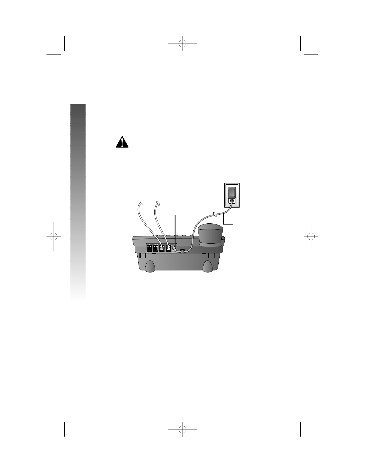
2 Connect the handset cord.
Plug one end of the coiled handset cord into the jack on the left
side of the phone. Plug the other end into the handset and hang up.
3 Connect the power adapter to the telephone.
Use only the power adapter provided with this product.
To obtain a replacement, call 1 800 222–3111.
Plug one end of the power adapter into the jack labeled POWER
on the back of the phone. Plug the other end into a standard
electrical outlet not controlled by a wall switch.
4 Check for dial tone.
Lift the handset and listen for a dial tone. If you cannot hear a dial
tone, turn to IN CASE OF DIFFICULTY beginning on page 88.
5 Initialization.
If no battery is installed when you connect the power cord,
the phone runs a quick self-test and the screen displays
Initializing.. for about three seconds.
¥
NOTE:The phone will run through this same initialization any time it is
reconnected to AC power if a working battery is not installed (for example,
after a power failure or when the unit has been unplugged).
14
INSTALLATION
INSTALLATION
Standard
Electrical
Outlet
Power adapter
POWER jack
974_CIB_1ATT_033104 3/31/2004 5:28 PM Page 14
Page 20
Wall Installation
For best results, follow the directions in “Battery Installation” on page 11
before installing the phone.
1 If the wedge is still attached to the underside of the base
unit, follow Step 1 in “Battery Installation” on page 11 to remove
the wedge.
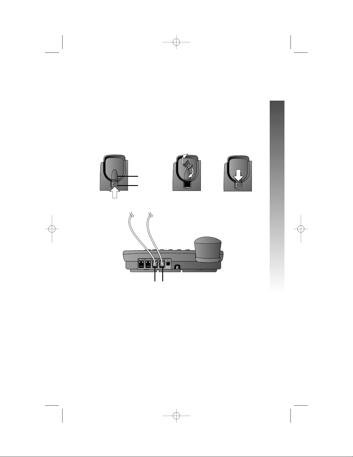
2 Reverse the handset tab.
Hold down the switchhook, then pull out the handset tab and
rotate it 180 degrees. Push the handset tab down into the
grooves so it settles into position.
3 Connect the telephone line cords to the telephone as shown.
4 Connect the handset cord.
Plug one end of the coiled handset cord into the jack on the left side
of the phone. Plug the other end into the handset and hang up.
continued on page 16
15
INSTALLATION
INSTALLATION
Switchhook
Handset tab
L3/L4 jack
L1/L2 jack
974_CIB_1ATT_033104 3/31/2004 5:28 PM Page 15
Page 21
Wall Installation
continued from page 15
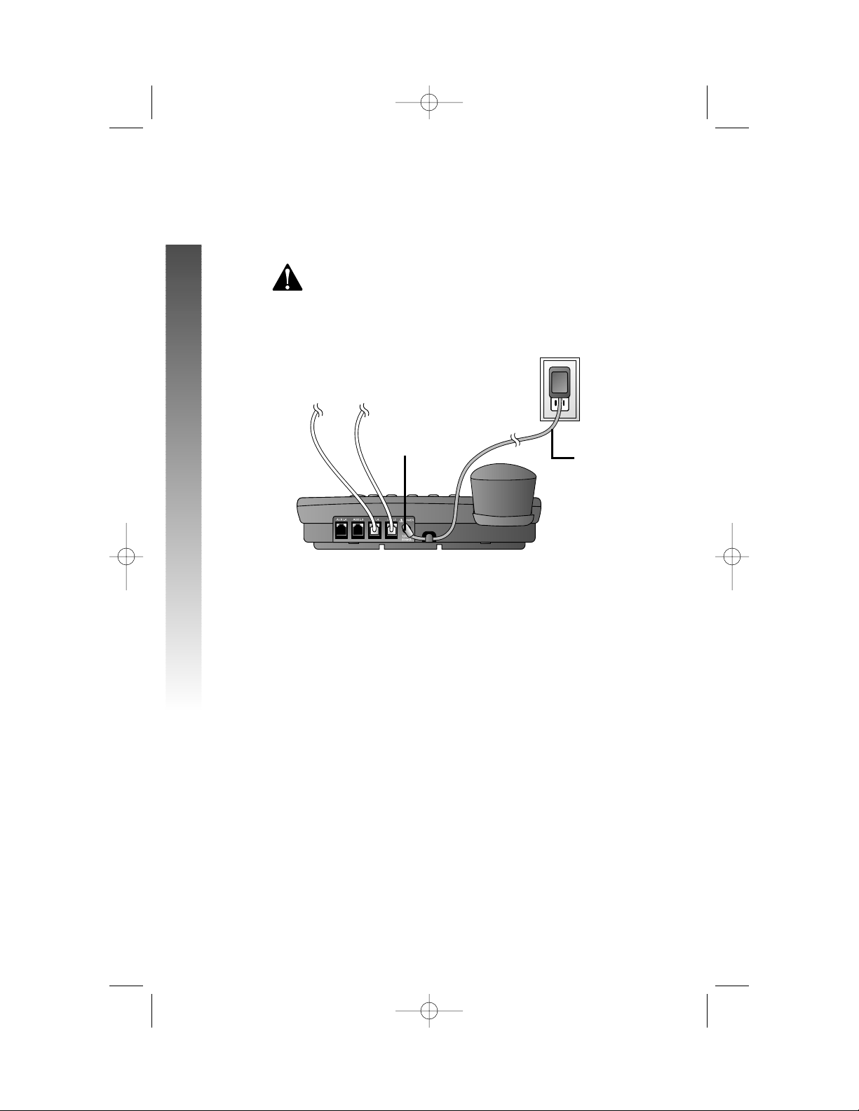
5 Connect the power adapter to the telephone.
Use only the power adapter provided with this product.
To obtain a replacement, call 1 800 222–3111.
Plug one end of the power adapter into the jack labeled POWER
on the back of the phone. Plug the power adapter into a standard
electrical outlet not controlled by a wall switch.
6 Check for dial tone.
Lift the handset and listen for a dial tone. If you cannot hear a dial
tone, turn to IN CASE OF DIFFICULTY beginning on page 88.
16
INSTALLATION
INSTALLATION
Standard
Electrical
Outlet
Power adapter
POWER jack
974_CIB_1ATT_033104 3/31/2004 5:28 PM Page 16
Page 22
7 Mount the phone on the wall.
• Four One-Line Jacks (To use this installation option, you’ll
need to purchase and install a blank wall plate.)
continued on page 18
17
INSTALLATION
INSTALLATION
Modular
telephone
jacks
Lines 3 and 4
Modular
telephone Jacks
Lines 1 and 2
Standard
electrical
outlet
Blank
wall
plate
Power
adapter
Two-line
adapters
974_CIB_1ATT_033104 3/31/2004 5:28 PM Page 17
Page 23
Wall Installation
continued from page 17
• Two Two-Line Jacks
8 Initialization.
If no battery is installed when you connect the power cord,
the phone runs a quick self-test and the screen displays
Initializing.. for about three seconds.
¥
NOTE:The phone will run through this same initialization any time it
is reconnected to AC power if a working battery is not installed (for
example, after a power failure or when the unit has been unplugged).
18
INSTALLATION
INSTALLATION
Modular
telephone jack
Lines 3 and 4
Modular
telephone jack
Lines 1 and 2
Standard
electrical
outlet
Power
adapter
974_CIB_1ATT_033104 3/31/2004 5:28 PM Page 18
Page 24
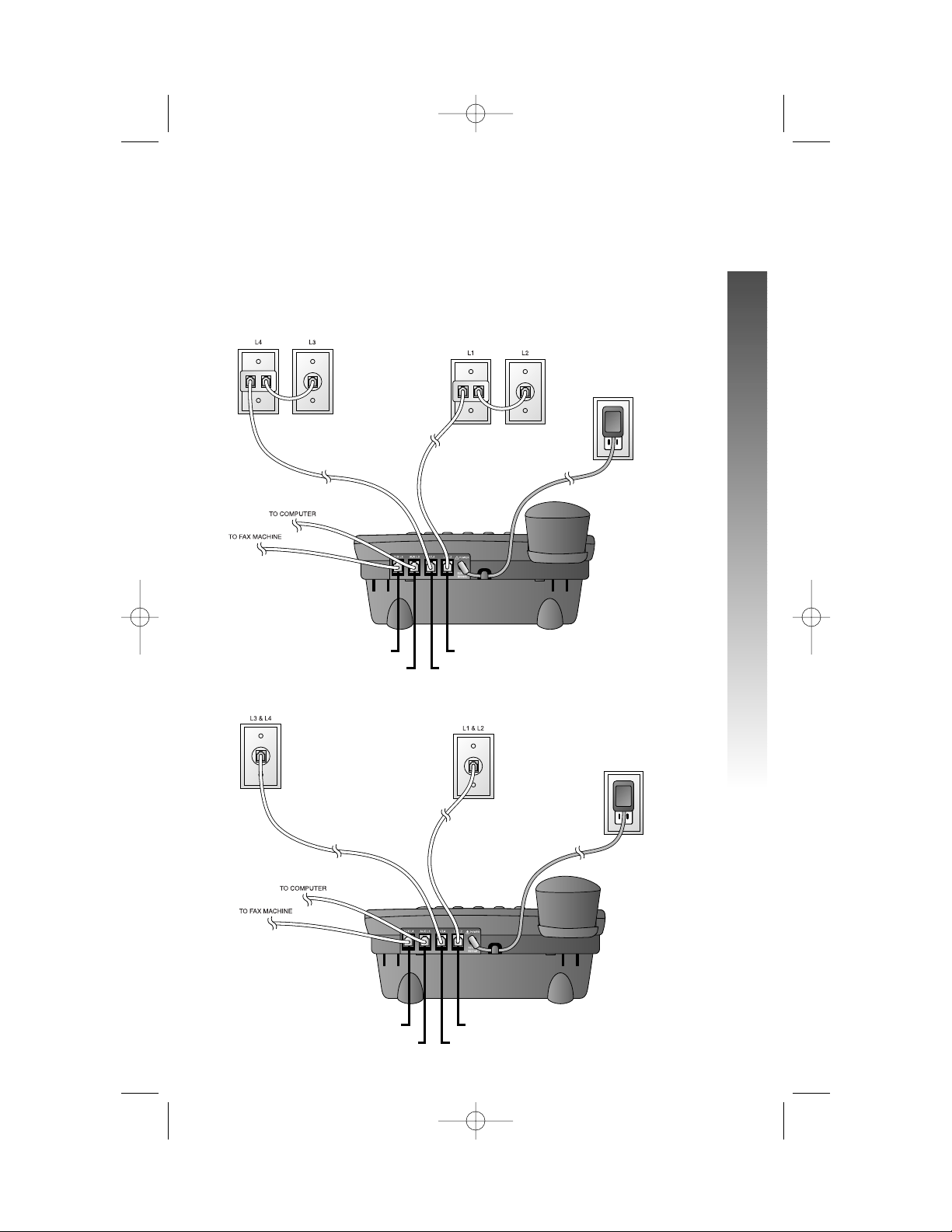
Convenience Ports
If you want to connect another device (such as a modem or fax machine)
to the wall jack, you can use the jacks on the phone labeled AUX. These
convenience ports use Lines 3 and 4; a call picked up on Line 3 or 4 at
another extension may interrupt fax, modem, or message transmission.
• Four One-Line Jacks
• Two Two-Line Jacks
19
INSTALLATION
INSTALLATION
Modular telephone
jacks Lines 3
and 4 with
two-line adapter
Modular telephone jacks
Lines 1 and 2 with
two-line adapter
Standard
electrical
outlet
Power adapter
L1/L2 jack
L3/L4 jack
AUX L4 jack
AUX L3 jack
Modular
telephone jack
Lines 3 and 4
Modular
telephone jack
Lines 1 and 2
Standard
electrical
outlet
Power adapter
L1/L2 jack
L3/L4 jack
AUX L4 jack
AUX L3 jack
974_CIB_1ATT_033104 3/31/2004 5:28 PM Page 19
Page 25
20
MENU OPERATION
MENU OPERATION
All of the feature setup,memory programming and some individual feature
operations for the 974 use menus shown in the screen display. Use the
navigation buttons (<,>, +, -, E) to begin, end and move through
menu operations (for example, feature setup).
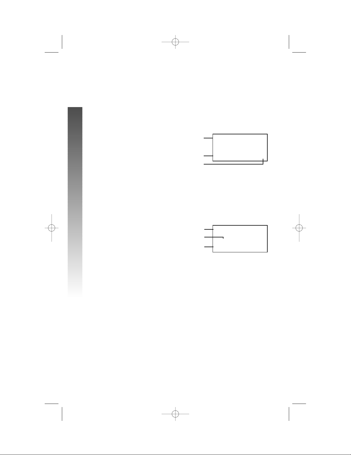
• Press E to activate a menu operation. The first menu item
for this topic or data will appear in line four of the screen. For
example, the screen displays:
¥
NOTE: If you do not press a key to continue menu operations within
30 seconds, the telephone automatically exits the menu.
• When x is displayed, you can press the - or + button repeatedly
to move through the menu.
• Press E to choose the menu item currently displayed. This
may be a lower level menu, an action, or a feature settings screen.
For example:
• When () is displayed, you can press the > or < button to scroll
through setting choices.
• Press E to store the setting, or press - to store the setting
and show the next option for the feature currently displayed.
• To return to the main menu, press the - or + button until the
screen display includes MAIN MENU or EXIT. Then, press E.
• To exit programming mode, press and hold E.
¥
NOTE: If the phone beeps twice, repeat the steps to program the feature.
ONE TOUCH
()Intercom
PREFERENCEHHHHHx
FEATUREHSETUP
ONEHTOUCHHHHHHHx
MENU OPERATION
Menu
Menu item
Menu topic or data
Menu indicator
Current Setting
Feature
974_CIB_1ATT_033104 3/31/2004 5:28 PM Page 20
Page 26

Menu Structure
Use the menu operation to set up the values for the 974 features. Access the
menu by pressing E when the phone is idle. The menu structure for the
feature setup menu is below.
ONE TOUCH
PREFERENCE
INTERCOM
TELEPHONE
PROGRAM
PAUSE
TONE
FLASH
CANCEL
VIEW
DONE
MAIN MENU
PHONE SETTINGS
EXTENSION NO
RINGER ON/OFF
RINGER TYPE
DELAY RING
AUTO-MUTE
TONE/PULSE
HOLD REMINDER
MAIN MENU
21
MENU OPERATION
MENU OPERATION
TIME/DATE
SPECIAL OPTIONS
LINE USAGE
PRIME LINE
AUTOMATIC MODE
SCROLL RATE
LCD BACKLIGHT
COVM ON/OFF
COVM RESET
AREA CODES
LINE GROUP
RESET ALL
MAIN MENU
CENTREX
CONSOLE
CSL DELAY RING
MAIN MENU
LANGUAGE
974_CIB_1ATT_033104 3/31/2004 5:28 PM Page 21
Page 27
Shortcut to Language Menu
This phone comes programmed for English screen displays.
If you need to change the screen language to Spanish or
French, you can use these steps to reach the LANGUAGE
menu more quickly.
1 Press E to begin feature setup.
2 Press + twice. The screen display includes
LANGUAGE and the current setting.
3 Press < or > to scroll through the language
choices (English, Espanol, or Français).
When the language you want to use is displayed,
press - to save your choice. The screen display
includes EXIT.
4 Press E to return to the idle screen.
¥
NOTE:You can exit feature setup and return to the
idle screen any time. Simply press and hold E.
Rapid Scroll
You can scroll through menu items or setting choices
more quickly using this feature. Press and hold the desired
scroll button (+,-, > or <). The screen will scroll
through your choices at the rate you program during
Feature Setup. See “Set the Scroll Rate” on page 34 for
programming instructions.
22
MENU OPERATION
MENU OPERATION
iiiii
kkk
ooo
mmm
jjj
iiiii
kkk
ooo
mmm
974_CIB_1ATT_033104 3/31/2004 5:28 PM Page 22
Page 28
Set One Touch Preference
Choose whether pressing an EXT button automatically
initiates an intercom or One Touch call. If you want to
place One Touch calls using only one button, set this
feature to TELEPHONE. If you want to place intercom
calls using only one button, set this feature to INTERCOM.
See ONE TOUCH OPERATION beginning on page 55 and
INTERCOM OPERATION beginning on page 67 for details
about One Touch and intercom calls.
1 Press E to begin feature setup.
2 Press E. The screen display includes
PREFERENCE and the current setting.
3 Press < or > to toggle between INTERCOM
and TELEPHONE.
4 When the correct setting is shown, press
- to save your choice. The screen display
includes PROGRAM.
5 Press and hold E to return to the idle
screen.
¥
NOTE:You can exit feature setup and return to the
idle screen any time. Simply press and hold E.
23
FEATURE SETUP
FEATURE SETUP
FEATURE SETUP
iiiii
kkk
ooo
nnnnn
974_CIB_1ATT_033104 3/31/2004 5:28 PM Page 23
Page 29
Assign an Extension Number
to Your Phone
Every individual phone in your telephone system MUST
be assigned a unique extension number for the intercom
feature to work.
1 Press E to begin feature setup.
2 Press - until the screen display includes PHONE
SETTINGS.
3 Press E. The screen display includes
EXTENSION NO and the current setting.
4 Press < or > to change the extension
number (11…26).
5 When the desired extension number is shown
press - to save your choice. The screen display
includes RINGER ON/OFF.
¥
NOTE: If you duplicate an extension number already in
use, you will hear a repeating shor t ring and the screen
display will include EXT XX is already used
Assign new EXT #. Repeat Steps 1–5 at the ringing
phone to assign a different extension number (from
11 – 26).
6 Proceed to Step 5 on page 25 to set the next
feature (Ringer On or Off)
— OR —
Press and hold E to return to the idle
screen.
¥
NOTE:You can exit feature setup and return to the
idle screen any time. Simply press and hold E.
24
FEATURE SETUP
FEATURE SETUP
iiiii
kkk
ooo
nnnnn
974_CIB_1ATT_033104 3/31/2004 5:28 PM Page 24
Page 30
Turn the Ringer On or Off
for Each Line
1 Press E to begin feature setup.
2 Press - until the screen display includes PHONE
SETTINGS.
3 Press E. The screen display includes
EXTENSION NO.
4 Press - until the screen display includes
RINGER ON/OFF.
5 Press E. The screen display includes L1
RINGER and the current setting.
6 Press < or > to toggle between On and Off
for the line shown.
7 When the desired setting for this line is shown,
press - to save your choice. The screen display
will include the current ringer setting for the
next line (L1...L4).
8 Repeat Steps 6 and 7 to turn the ringer on
or off for other lines at this phone.
9 When you are finished setting the ringer, press
- until the screen display includes DONE.
10 Press E. The screen display includes
RINGER ON/OFF.
11 Proceed to Step 4 on page 26 to set the next
feature (Ringer Type)
— OR —
Press and hold E to return to the idle
screen.
¥
NOTE:You can exit feature setup and return to the
idle screen any time. Simply press and hold E.
25
FEATURE SETUP
FEATURE SETUP
iiiii
kkk
ooo
jjj
974_CIB_1ATT_033104 3/31/2004 5:28 PM Page 25
Page 31

Select the Ringer Type
You can choose a ring pattern for incoming phone calls.
¥
NOTE: Incoming intercom calls use Ringer Type 1
and cannot be changed.
1 Press E to begin feature setup.
2 Press - until the screen display includes PHONE
SETTINGS.
3 Press E. The screen display includes
EXTENSION NO.
4 Press - until the screen display includes
RINGER TYPE.
5 Press E. The screen display includes L1
RINGER TYPE and the current setting.
6 Press < or > to change the ringer type
(Type 1 …Type 4) for the line shown.
7 When the desired setting for this line is shown,
press - to save the your choice and
move to the next line with its ringer type.
8 Repeat Steps 6 and 7 to set ringer types
for other lines on this phone (L1...L4).
9 When you are finished setting the ringer
type, press - until the screen display includes
DONE.
10 Press E. The screen display includes
RINGER TYPE.
11 Proceed to Step 4 on page 27 to set the
next feature (Delay Ring)
— OR —
Press and hold E to return to the idle
screen.
¥
NOTE:You can exit feature setup and return to the
idle screen any time. Simply press and hold E.
26
FEATURE SETUP
FEATURE SETUP
iiiii
kkk
ooo
nnnnn
974_CIB_1ATT_033104 3/31/2004 5:28 PM Page 26
Page 32

Set Delay Ring
Set the length of time before incoming calls will ring at
this extension.
¥
NOTE: If you choose to set a delayed ring on a phone
with Voice Mail service, the phone may not ring at all
before Voice Mail picks up the call.
1 Press E to begin feature setup.
2 Press - until the screen display includes PHONE
SETTINGS.
3 Press E. The screen display includes
EXTENSION NO.
4 Press - until the screen display includes DELAY
RING and the current setting.
5 Press < or > to change the delay ring setting
(Off, 2 sec…30 sec).
6 When the correct delay setting is shown, press
- to save your choice. The screen display
includes Auto-Mute.
7 Proceed to Step 5 on page 28 to set the next
feature (Auto-Mute)
— OR —
Press and hold E to return to the idle
screen.
¥
NOTE:You can exit feature setup and return to the
idle screen any time. Simply press and hold E.
27
FEATURE SETUP
FEATURE SETUP
iiiii
kkk
ooo
jjj
974_CIB_1ATT_033104 3/31/2004 5:28 PM Page 27
Page 33

Turn Auto-Mute On or Off
Choose whether sounds at this extension will be heard
automatically in response to a page (Auto-Mute Off) or
only when M is pressed. Auto-Mute Off permits
hands-free conversation and room monitoring;
Auto-Mute On protects privacy.
1 Press E to begin feature setup.
2 Press - until the screen display includes PHONE
SETTINGS.
3 Press E. The screen display includes
EXTENSION NO.
4 Press - until the screen display includes
Auto-Mute and the current setting.
5 Press < or > to toggle between On and Off.
6 When the correct setting is shown, press -
to save your choice. The screen display includes
TONE/PULSE.
7 Proceed to Step 5 of “Set Dial Mode” on
page 29 to set the next feature (Tone/Pulse)
— OR —
Press and hold E to return to the idle
screen.
¥
NOTE:You can exit feature setup and return to the
idle screen any time. Simply press and hold E.
28
FEATURE SETUP
FEATURE SETUP
iiiii
kkk
ooo
nnnnn
974_CIB_1ATT_033104 3/31/2004 5:28 PM Page 28
Page 34

Set Dial Mode
1 Press E to begin feature setup.
2 Press - until the screen display includes PHONE
SETTINGS.
3 Press E. The screen display includes
EXTENSION NO.
4 Press - until the screen display includes
TONE/PULSE and the current setting.
5 Press < or > to toggle between Tone
and Pulse.
6 When the correct setting is shown, press
- to save your choice. The screen display
includes HOLD REMINDER.
7 Proceed to Step 5 below to set the next
feature (Hold Reminder)
— OR —
Press and hold E to return to the idle
screen.
¥
NOTE:You can exit feature setup and return to the
idle screen any time. Simply press and hold E.
Turn Hold Reminder On or Off
1 Press E to begin feature setup.
2 Press - until the screen display includes PHONE
SETTINGS.
3 Press E. The screen display includes
EXTENSION NO.
4 Press - until the screen display includes HOLD
REMINDER and the current setting.
5 Press < or > to toggle between On and Off.
6 When the correct setting is shown, press -
to save your choice. The screen display
includes MAIN MENU.
7 Press and hold E to return to the idle
screen.
¥
NOTE:You can exit feature setup and return to the
idle screen any time. Simply press and hold E.
29
FEATURE SETUP
FEATURE SETUP
iiiii
kkk
ooo
nnnnn
iiiii
kkk
ooo
nnnnn
974_CIB_1ATT_033104 3/31/2004 5:28 PM Page 29
Page 35

Set the Time and Date
1 Press E to begin feature setup.
2 Press - until the screen display includes
TIME/DATE.
3 Press E. The screen display includes
HOUR and the current hour setting.
4 Press < or > until the correct hour is shown.
5 Press - to save the hour setting. The screen
display includes MINUTE and the current minute
setting.
6 Press < or > until the correct minute is shown.
7 Press - to save the minute setting. The screen
display includes AM/PM and the current setting.
8 Press < or > to toggle between AM and PM.
9 Press - to save the AM/PM setting. The screen
display includes MONTH and the number of the
current month setting.
10 Press < or > until the number of the correct
month is shown.
11 Press - to save the correct month setting. The
screen display includes DATE and the current
day of the month setting.
12 Press < or > until the correct day of the
month is shown.
13 Press - to save the day of the month. The
screen display includes DAY OF WEEK and
the current setting.
14 Press < or > until the correct day of the
week is shown.
15 Press - to save the Time/Date setting. The
screen display includes MAIN MENU.
16 Press and hold E to return to the idle
screen.
¥
NOTE:You can exit feature setup and return to the
idle screen any time. Simply press and hold E.
30
FEATURE SETUP
FEATURE SETUP
iiiii
kkk
ooo
nnnnn
974_CIB_1ATT_033104 3/31/2004 5:28 PM Page 30
Page 36

Turn Line Usage On or Off for
Each Line
If you are not using all four phone lines at this extension,
you need to turn off Line Usage for the unused lines.
If you expand to a second, third or fourth line, turn Line
Usage back on.
You may also restrict the use of certain lines on this phone
to intercom and paging only, by turning off Line Usage for
each line you want restricted. When Line Usage is turned
off, that line cannot be used to answer incoming calls or to
make outgoing or transfer calls.
1 Press E to begin feature setup.
2 Press - until the screen display includes
SPECIAL OPTIONS.
3 Press E. The screen display includes LINE
USAGE.
4 Press E. The screen display includes L1
USAGE and the current setting for this line.
5 Press < or > to toggle between On and Off
for the line shown.
6 Press - to save the current setting for this line
and move to the next line with its current Line
Usage setting.
7 Repeat Steps 5 and 6 to set Line Usage for
other lines at this extension.
8 When you are finished setting Line Usage,
press - until the screen display includes DONE.
9 Press E. The screen display includes LINE
USAGE.
10 Proceed to Step 4 on page 32 to set up the
next feature (Prime Line)
— OR —
Press and hold E to return to the idle
screen.
¥
NOTE:You can exit feature setup and return to the
idle screen any time. Simply press and hold E.
31
FEATURE SETUP
FEATURE SETUP
iiiii
kkk
ooo
nnnnn
974_CIB_1ATT_033104 3/31/2004 5:28 PM Page 31
Page 37

Assign the Prime Line
(Line Preference)
1 Press E to begin feature setup.
2 Press - until the screen display includes
SPECIAL OPTIONS.
3 Press E. The screen display includes LINE
USAGE.
4 Press - until the screen display includes PRIME
LINE and the current setting.
5 Press < or > to scroll through the line
choices (Line 1...Line 4).
6 When the line you wish to set as prime is
displayed, press - to save your choice.
The screen display includes AUTOMATIC MODE.
7 Proceed to Step 5 on page 33 to set the
next feature (Automatic Mode)
— OR —
Press and hold E to return to the idle
screen.
¥
NOTE:You can exit feature setup and return to the
idle screen any time. Simply press and hold E.
32
FEATURE SETUP
FEATURE SETUP
iiiii
kkk
ooo
nnnnn
974_CIB_1ATT_033104 3/31/2004 5:28 PM Page 32
Page 38

33
FEATURE SETUP
FEATURE SETUP
Set Automatic Mode
Choose the mode (headset or speakerphone) to be used
automatically when you press a LINE button with the
handset in the cradle.
1 Press E to begin feature setup.
2 Press - until the screen display includes
SPECIAL OPTIONS.
3 Press E. The screen display includes LINE
USAGE.
4 Press - until the screen display includes
AUTOMATIC MODE and the current setting.
5 Press < or > to toggle between
SpeakerPhone and Headset.
6 When the desired mode is displayed, press
- to save your choice. The screen display
includes SCROLL RATE.
7 Proceed to Step 5 on page 34 to set the
next feature (Scroll Rate)
— OR —
Press and hold E to return to the idle
screen.
¥
NOTE:You can exit feature setup and return to the
idle screen any time. Simply press and hold E.
iiiii
kkk
ooo
nnnnn
974_CIB_1ATT_033104 3/31/2004 5:28 PM Page 33
Page 39

Set the Scroll Rate
You can choose the speed for the Rapid Scroll feature.
(See “Rapid Scroll” on page 22 for details.)
1 Press E to begin feature setup.
2 Press - until the screen display includes
SPECIAL OPTIONS.
3 Press E. The screen display includes LINE
USAGE.
4 Press - until the screen display includes
SCROLL RATE and the current setting.
5 Press < or > to change the setting (Very
Slow, Slow, Medium, Fast, or Very Fast).
6 When the correct scroll rate is shown, press
- to save your choice. The screen display
includes LCD BACKLIGHT.
7 Proceed to Step 5 on page 35 to set the
next feature (LCD Backlight)
— OR —
Press and hold E to return to the idle
screen.
¥
NOTE:You can exit feature setup and return to the
idle screen any time. Simply press and hold E.
34
FEATURE SETUP
FEATURE SETUP
iiiii
kkk
ooo
nnnnn
974_CIB_1ATT_033104 3/31/2004 5:28 PM Page 34
Page 40

Turn Screen Backlight On or Off
1 Press E to begin feature setup.
2 Press - until the screen display includes
SPECIAL OPTIONS.
3 Press E. The screen display includes LINE
USAGE.
4 Press - until the screen display includes LCD
BACKLIGHT and the current setting.
5 Press < or > to toggle between On and Off.
6 When the correct setting is shown, press -
to save your choice. The screen display includes
COVM ON/OFF.
7 Proceed to Step 5 on page 36 to set the next
feature (COVM ON/OFF)
— OR —
Press and hold E to return to the idle
screen.
¥
NOTE:You can exit feature setup and return to the
idle screen any time. Simply press and hold E.
35
FEATURE SETUP
FEATURE SETUP
iiiii
kkk
ooo
nnnnn
974_CIB_1ATT_033104 3/31/2004 5:28 PM Page 35
Page 41

Turn COVM Indicators On or Off
for Each Line
If you subscribe to Voice Mail service with your local
telephone service provider, turn the COVM indicator on
to have the screen display the appropriate line numbers
when there are messages waiting. If you do not subscribe
to Voice Mail service, turn the COVM indicators off for
each line.
1 Press E to begin feature setup.
2 Press - until the screen display includes
SPECIAL OPTIONS.
3 Press E. The screen display includes LINE
USAGE.
4 Press - until the screen display includes COVM
ON/OFF.
5 Press E. The screen display includes L1
COVM ON/OFF and the current setting.
6 Press < or > to toggle between On and Off
for the line shown.
7 When the correct setting is shown, press - to
save your choice. The screen display includes
COVM ON/OFF for the next line and the current
setting.
8 Repeat Steps 6 and 7 to turn the COVM
indicator on or off for other lines at this
extension.
9 When you are finished setting the COVM
indicators, press - until the screen display
includes DONE.
10 Press E. The screen display includes
COVM ON/OFF.
11 Press - until the screen display includes
COVM RESET, then proceed to Step 5 on
page 37 to clear the COVM indicators
— OR —
Press and hold E to return to the idle screen.
¥
NOTE:You can exit feature setup and return to the
idle screen any time. Simply press and hold E.
36
FEATURE SETUP
FEATURE SETUP
iiiii
kkk
ooo
nnnnn
974_CIB_1ATT_033104 3/31/2004 5:28 PM Page 36
Page 42

Reset COVM Indicator
If a COVM indicator remains on when there are no
messages on that line, you may have received a false signal
from your local telephone service provider. You can clear
the indicator manually.
1 Press E to begin feature setup.
2 Press - until the screen display includes
SPECIAL OPTIONS.
3 Press E. The screen display includes LINE
USAGE.
4 Press - until the screen display includes COVM
RESET.
5 Press E. The screen display includes
L1 COVM RESET.
6 Press + or - to scroll through the COVM
Reset menu (L1 COVM RESET...L4 COVM
RESET, or ALL COVM RESET).
7 When the line you want to reset is displayed,
press E to remove the message waiting
indicator. You can clear all the lines at once by
choosing ALL COVM RESET. The screen display
includes Reset!.
8 Press - until the screen display includes DONE.
9 Press E. The screen display includes
COVM RESET.
10 Press - until the screen display includes
AREA CODES, then proceed to Step 5 on
page 38 to program the Home or Local Area
Codes.
— OR —
Press and hold E to return to the idle screen.
¥
NOTE:You can exit feature setup and return to the
idle screen any time. Simply press and hold E.
37
FEATURE SETUP
FEATURE SETUP
iiiii
mmm
jjj
974_CIB_1ATT_033104 3/31/2004 5:28 PM Page 37
Page 43

Program Home and Local
Area Codes
You can program this phone to recognize one Home and
up to five Local Area Codes. See “Home Area Code” and
“Local Area Codes” on page 6 for definitions.
1 Press E to begin feature setup.
2 Press - until the screen display includes
SPECIAL OPTIONS.
3 Press E. The screen display includes LINE
USAGE.
4 Press - until the screen display includes AREA
CODES.
5 Press E. The screen display includes HOME
AC and the current setting.
6 Use the dial pad keys to enter your Home Area
Code, then press -. The screen display includes
LOCAL AC1 and the current setting.
If you need to enter any Local Area Codes, use
the dial pad keys and then press - to scroll to
the next screen (LOCAL AC2, LOCAL AC3,
LOCAL AC4, and LOCAL AC5).
¥
NOTE: If you must dial the area code to place
calls within your own area code, enter “000” for the
Home Area Code and enter your area code as a
Local Area Code.
7 When you are finished entering all of the area
codes you need to program, press - until the
screen display includes DONE.
8 Press E. The screen display includes AREA
CODES.
9 Press - until the screen display includes LINE
GROUP, then proceed to Step 5 on page 39 to
assign the line group
— OR —
Press and hold E to return to the idle
screen.
¥
NOTE:You can exit feature setup and return to the
idle screen any time. Simply press and hold E.
38
FEATURE SETUP
FEATURE SETUP
iiiii
nnnnn
974_CIB_1ATT_033104 3/31/2004 5:28 PM Page 38
Page 44

Assign the Line Group
for this Phone
1 Press E to begin feature setup.
2 Press - until the screen display includes
SPECIAL OPTIONS.
3 Press E. The screen display includes LINE
USAGE.
4 Press - until the screen display includes LINE
GROUP and the current setting.
5 Press > or < to scroll through the Line Group
choices (Line 04...Line15, or PRV).
6 When the Line Group you want is shown,
press - to save your choice. The screen display
includes RESET ALL.
7 Proceed to Step 5 on page 40 to reset all
feature settings to default values
— OR —
Press and hold E to return to the idle
screen.
¥
NOTE:You can exit feature setup and return to the
idle screen any time. Simply press and hold E.
39
FEATURE SETUP
FEATURE SETUP
iiiii
kkk
ooo
nnnnn
974_CIB_1ATT_033104 3/31/2004 5:28 PM Page 39
Page 45

Erase All Settings and Return the
Phone to Default Settings
If you reset all features to the default settings,
all previous feature programming will be erased.
You will need to program your preferences
for every feature again. You cannot undo the
RESET ALL command.
1 Press E to begin feature setup.
2 Press - until the screen display includes
SPECIAL OPTIONS.
3 Press E. The screen display includes LINE
USAGE.
4 Press - until the screen display includes RESET
ALL.
5 Press E. The screen display includes
ENTER:Reset all?.
6 Press E to confirm the command. The
screen displays Reset!. A tone sounds and
the screen returns to showing RESET ALL.
7 Press and hold E to return to the idle
screen.
¥
NOTE:You can exit feature setup and return to the
idle screen any time. Simply press and hold E.
40
FEATURE SETUP
FEATURE SETUP
iiiii
nnnnn
974_CIB_1ATT_033104 3/31/2004 5:28 PM Page 40
Page 46

You will need to program the next two features if
this phone is the designated Console Phone for
your Centrex system.
Set This Phone to be the Centrex
Console Phone
¥
NOTE: This feature is for use with Centrex
systems only.
1 Press E to begin feature setup.
2 Press - until the screen display includes
CENTREX.
3 Press E. The screen display includes
CONSOLE and the current setting.
4 Press < or > to toggle between On and Off.
5 Press - to save your choice. The screen display
includes CSL DELAY RING.
6 Proceed to Step 5 of “Set the Centrex Console
Delayed Ring Time” on page 42 to change the
next feature (Console Delay Ring)
— OR —
Press and hold E to return to the idle
screen.
¥
NOTE:You can exit feature setup and return to the
idle screen any time. Simply press and hold E.
41
FEATURE SETUP
FEATURE SETUP
iiiii
kkk
ooo
nnnnn
974_CIB_1ATT_033104 3/31/2004 5:28 PM Page 41
Page 47

Set the Centrex Console
Delayed Ring Time
¥
NOTE: This feature is for use with Centrex
systems only.
Set the length of time the phone will route your calls
to the Centrex Console phone. One ring is about
six seconds.
1 Press E to begin feature setup.
2 Press - until the screen display includes
CENTREX.
3 Press E. The screen display includes
CONSOLE.
4 Press - until the screen display includes CSL
DELAY RING and the current setting.
5 Press < or > to scroll through the choices
(Off, 02 sec...30 sec).
6 Press - to save your choice. The screen display
includes MAIN MENU.
7 Press and hold E to return to the idle
screen.
¥
NOTE:You can exit feature setup and return to the
idle screen any time. Simply press and hold E.
Set the Display Language
1 Press E to begin feature setup.
2 Press - until the screen display includes
LANGUAGE and the current setting.
3 Press < or > to scroll through the language
choices (English, Espanol, or Français).
When the language you want to use is displayed,
press - to save your choice. The screen display
includes EXIT.
4 Press E to return to the idle screen.
¥
NOTE:You can exit feature setup and return to the
idle screen any time. Simply press and hold E.
42
FEATURE SETUP
FEATURE SETUP
iiiii
kkk
ooo
nnnnn
iiiii
kkk
ooo
nnnnn
974_CIB_1ATT_033104 3/31/2004 5:28 PM Page 42
Page 48

¥
NOTE: When you make a call, the phone selects the
Prime Line you programmed (See “Assign the Prime
Line” on page 32). When you answer a call, the phone
automatically selects the ringing line.
Make or Answer a Call
¥
NOTE: This phone will automatically make and
answer calls in the mode (speakerphone or headset)
you programmed (see “Set Automatic Mode” on
page 33). Follow the directions below to choose a
mode manually. If the phone is in use on one line, any
other calls made or answered will use the same mode
already in use.
¥
NOTE: If you dial a phone number longer than 15
digits, the screen will display only the last 13 digits.
Handset
To make a call, lift the handset and dial the call.
To answer a call, lift the handset. Replace the handset
to end the call.
To override automatic line selection, lift the handset,
then press and release a LINE button
— OR —
Press the LINE button for the line you wish to select,
then lift the handset.
continued on page 44
43
TELEPHONE OPERATION
TELEPHONE OPERATION
TELEPHONE OPERATION
iiiiiiiiiiiiiiiiiiii
974_CIB_1ATT_033104 3/31/2004 5:28 PM Page 43
Page 49

Make or Answer a Call
continued from page 43
Speakerphone
To make a call, press and release the desired LINE
button or K. The SPEAKER light goes on. Wait
for a dial tone, then dial the call. Press K to end
the call.
To answer a call, press K or press the LINE
button of the incoming call. Press K again to
end the call.
¥
NOTE: If headset is programmed as the default mode
(see “Set Automatic Mode” on page 33), you must
press K to activate the speakerphone.
Headset
You can use this phone hands-free when you install any
industry standard two-band 2.5mm headset (purchased
separately). For best results use an AT&T two-band
2.5mm headset.
Make sure the headset is plugged into the headset jack.
You will hear a double-beep if you press h when
the headset is not plugged in.
¥
NOTE: If headset is programmed as the default mode,
(see “Set Automatic Mode” on page 33) but the
headset is not plugged in, the phone will switch to
speakerphone.
To make a call, press and release h or press
the desired LINE button and then press h. The
HEADSET light goes on. Wait for a dial tone, then dial
the call. Press h to end the call.
To answer a call, press h. Press h
again to end the call.
¥
NOTE: If speakerphone is programmed as the default
mode (See “Set Automatic Mode” on page 33), you
must press h to activate the headset.
44
TELEPHONE OPERATION
TELEPHONE OPERATION
iiiiiiiiiiiiiiiiiiii
kkk
iiiiiiiiiiiiiiiiiiii
kkk
974_CIB_1ATT_033104 3/31/2004 5:28 PM Page 44
Page 50

Switch Between Handset, Headset
and Speakerphone
To switch from handset to headset or
speakerphone, press h or K, then replace
the handset. (In order to use the headset, it must be
plugged in.)
To switch from speakerphone to handset, lift
the handset. (Do not press K or the call will be
disconnected.)
To switch from headset to handset when the handset
is in the cradle, lift the handset.
To switch from headset to handset when the handset
is off-hook, press h again.
To switch from headset to speakerphone, press
K.
To switch from speakerphone to headset, insert the
headset plug into the jack, and press h.
To override automatic line selection, press and
release a LINE button. This activates the speakerphone or
headset, whichever is programmed as the default mode.
Timer
When you make or answer a call, the timer automatically
starts. The screen displays the elapsed time in minutes and
seconds for the first hour (up to 59:59) and then begins
again. The timer stops automatically when you hang up
and the recorded time is displayed for about 10 seconds.
The timer also stops when you place a call on hold and
resets to 00:00 when you release hold.
45
TELEPHONE OPERATION
TELEPHONE OPERATION
iiiiiiiiiiiiiiiiiiii
kkk
kkk
974_CIB_1ATT_033104 3/31/2004 5:28 PM Page 45
Page 51

46
TELEPHONE OPERATION
TELEPHONE OPERATION
Call Privacy
To ensure call privacy, this phone allows only one set at
a time to use a line.
Cancel Call Privacy
During the call, press the LINE button for the call.
You’ll hear a short beep. Others can now join the call.
Restore Call Privacy
Press the LINE button again during the call. You’ll hear
a double-beep. The other phones will be dropped from
the call.
¥
NOTE: Call privacy is automatically restored when
you end the call.
¥
NOTE: When a non-system phone answers a call,
any other system phone can pick up the call by pressing
the LINE button. Once a system phone picks up the
call, Call Privacy is activated and no other system
phones can listen to the call unless Call Privacy is
canceled, but non-system phones which share that
line can still join the call.
Do Not Disturb
When your phone is off-hook (i.e., you are on a call) you
will hear a low volume ring when you receive an intercom
call. In order to prevent even this audible signal, activate
the Do Not Disturb (DND) feature. When you activate
this feature you will not hear paging tones, voice paging, or
incoming call rings. Instead, the LINE light flashes and the
INTERCOM light goes on to signal an incoming call or
page. If you receive an intercom call, the INTERCOM light
flashes, and the number of the intercom extension calling
you appears on the display.
1 Press N to prevent interruptions. The DND
light goes on and the screen display includes DND.
2 Press N again to resume normal call alerts.
The DND light goes off and the screen no longer
shows DND.
When this feature is activated, callers from within your
phone system will hear a short repeating tone (like a fast
busy signal).
iiiiiiiiiiiiiiiiiiii
ppp
974_CIB_1ATT_033104 3/31/2004 5:28 PM Page 46
Page 52

Volume
Handset/Speakerphone/Headset
Volume Control
When you are on a call, press VOLUME + to increase
call volume. Press VOLUME - to decrease volume.
You will hear a beep when you reach the minimum or
maximum level.
Ringer Volume
When the phone is ringing, press VOLUME + or
VOLUME - to adjust the ringer volume.This phone
has four ringer volume levels. As you adjust the ringer,
you will hear the ring change.
Turning Ringer Off
You may turn the ringer for each line on or off. For
detailed instructions see “Turn the Ringer On/Off for
Each Line” on page 25.
Redial
The last number dialed from this extension (up to 32
digits) is stored in redial memory until you dial another
number.
Handset
To dial the same number again, lift the handset,listen for
the dial tone, then press R. If there is no
number stored in redial memory, the screen display briefly
includes (empty) and then returns to the idle screen.
Speakerphone or Headset
To dial the same number again, press a LINE button, then
press R. The phone automatically dials the last
number. If there is no number stored in redial memory,
the screen display briefly includes (empty) and then
returns to the idle screen.
¥
NOTE: You will experience a delay before the call
is dialed when using the Redial feature. This is normal.
47
TELEPHONE OPERATION
TELEPHONE OPERATION
lll
jjj
jjj
974_CIB_1ATT_033104 3/31/2004 5:28 PM Page 47
Page 53

Redial Stack
The last six numbers dialed from this extension are
automatically stored in the redial memory stack. You can
review the numbers in the redial memory and dial one if
you wish.
1 When the phone is not on a call, press
R.
2 Press + or - to scroll through the last six
numbers dialed at this extension.
3 When the number you want to call is displayed,
press E or a LINE button. The call is dialed
automatically using the mode (headset or
speakerphone) you programmed as the
Automatic Mode. (See “Set Automatic Mode”
on page 33.)
¥
NOTE: If you do not place a call within 30 seconds,
the screen returns to idle.
Auto Redial
This phone can automatically redial a number every 60
seconds up to ten times, or until the other line rings or
you cancel Auto Redial.
1 Follow the instructions under “Redial Stack”
above to find the number you want to call.
2 Press a LINE button
— OR —
Press E. The phone will dial the call.
3 When the other line rings or the other party
answers, lift the handset
— OR —
Press K
— OR —
Press h and speak with the other party.
¥
NOTE: You will hear a double-beep if you press
h when the headset is not plugged in.
To cancel Auto Redial,press any button except VOLUME +
or VOLUME -.
48
TELEPHONE OPERATION
TELEPHONE OPERATION
lll
iiiii
jjj
mmm
mmm mmmmmmmmm
lll
mmm mmmmmmmmm
kkk
kkk
974_CIB_1ATT_033104 3/31/2004 5:28 PM Page 48
Page 54

Hold
While on a call, press and release H. The LINE light for
the line on hold flashes slowly in green, and a double-beep
sounds every 30 seconds to remind you the call is on
hold. (To turn off the reminder beep, see “Turn Hold
Reminder On or Off” on page 29.) You can replace the
handset
in the cradle without disconnecting the call. The
speakerphone is automatically turned off.
To release Hold, press and release the LINE button of the
call on hold.
¥
NOTE: The phone automatically disconnects a call on
hold after 20 minutes. To keep a call on hold longer
than 20 minutes, release Hold before 20 minutes and
then place the call on hold again.
¥
NOTE: You cannot put an intercom call on hold.
¥
NOTE: If a line is in use, pressing I will place
the line on hold and activate the intercom.
Switch Between Lines
1 Press and release H to keep a call on the
first line.
2 Press and release the LINE button of another
line to make or answer another call.
¥
NOTE: If you switch lines without pressing H first,
you will drop the call.
49
TELEPHONE OPERATION
TELEPHONE OPERATION
iiiiiiiiiiiiiiiiiiii
lll
iiiiiiiiiiiiiiiiiiii
lll
974_CIB_1ATT_033104 3/31/2004 5:28 PM Page 49
Page 55

Mute
Mute allows you to hear the other party, but the other
party can’t hear you.
To activate this feature, press and release M. The
MUTE light goes on.
To return to the conversation, press and release
M again.
¥
NOTE: Switching from handset to speakerphone or
headset, or from speakerphone or headset to handset,
changing lines, and putting a call on hold also cancels
Mute.
Flash
Use F instead of the switchhook to activate
telephone company subscriber services such as Call
Waiting or Three-Way Calling.
Temporary Tone Dialing
If you have dial pulse (rotary) service, you can change
from dial pulse to touch tone dialing during a call by
pressing t.
1 Dial the number.
2 Press and release t. Buttons pressed after
this send touch tone signals.
3 After you hang up, the phone automatically
returns to pulse service.
50
TELEPHONE OPERATION
TELEPHONE OPERATION
kkk
ppp
iiiii
974_CIB_1ATT_033104 3/31/2004 5:28 PM Page 50
Page 56

Conference Calls
This feature lets you set up a three-party call by using two
lines at the same time. You can also join an intercom call
with a call on an outside line. The outside line call must
be established first because an intercom call cannot be
placed on hold.
1 Make or answer a call.
2 Press and release H.
3 Call someone on another line.
4 When this call is answered, press C.
The three-party conference begins immediately.
5 To end a conference call, hang up. All parties
will disconnect.
To talk privately with one party:
1 Press H to place both lines on hold.
2 Press a LINE button to talk privately with the
person on that line.
3 Press C to resume the conference call.
¥
NOTE: An intercom call cannot be placed on hold.
If one party is on the intercom, that party will be
dropped from the call if you press H.
To drop one line:
Press the LINE button of the party you want to keep.
The other line will be dropped.
¥
NOTE: Occasionally, the far-end par ties on a
conference call might not hear one another.
51
TELEPHONE OPERATION
TELEPHONE OPERATION
iiiiiiiiiiiiiiiiiiii
ppp
ppp
974_CIB_1ATT_033104 3/31/2004 5:28 PM Page 51
Page 57

Transfer a Call
You can transfer a call you answer to any other system
phone. Once you transfer a call, it can be picked up at
any other system phone, not just at the extension you
called. For information about using the display screen
menus, see MENU OPERATION beginning on page 20.
¥
NOTE: If a transferred call is not picked up within
20 minutes, the phone will automatically disconnect
the call.
Blind Transfer
While on a call:
1 Press t. The screen displays:
2 Press the EXT button for the extension where
you’re transferring the call
— OR —
Dial the extension number where you’re
transferring the call. The screen displays:
3 Hang up.
Your phone reminds you with a double-beep every
30 seconds when a transferred call has not been
answered.
¥
NOTE: If you do not dial an extension within 10
seconds, the transfer is automatically cancelled.
12:08HPMHHH12/26
EXTH11
TransferH12
12:08HPMHHH12/26
EXTH11
Transfer
52
TELEPHONE OPERATION
TELEPHONE OPERATION
lll
ppp
nnnnn
974_CIB_1ATT_033104 3/31/2004 5:28 PM Page 52
Page 58

Transfer a Call and Speak to the
Receiving Party
While on a call:
1 Press H.
2 Press I. The screen displays:
3 Press E. The screen displays
4 Press the EXT button for the extension where
you’re transferring the call. The screen displays:
When the other party answers you can announce
the call.
5 Press T,then press the EXT button for
the extension where you’re transferring the call.
¥
NOTE: If you do not dial an extension within 10
seconds, the transfer is automatically cancelled.
Answer a Transferred Call
When you hear a long transfer ring, pick up the handset or
press the LINE button of the call to use the speakerphone
or headset.
Low Battery Indicator
The screen displays LOW BATT when the battery needs
to be replaced, or when no battery is installed.
12:08HPMHHH12/26
EXTH11
PAGEH12
12:08HPMHHH12/26
EXTH11
Paging
PAGE
12:08HPMHHH12/26
EXTH11
INTERCOMHTO_
PAGEHHHHHHHHHHHx
53
TELEPHONE OPERATION
TELEPHONE OPERATION
lll
ppp
nnnnn
lll
ppp
ppp
iiiiiiiiiiiiiiiiiiii
974_CIB_1ATT_033104 3/31/2004 5:28 PM Page 53
Page 59

54
TELEPHONE OPERATION
TELEPHONE OPERATION
Lights and What They Mean
LIGHT: STATUS: MEANS:
LINE On steadily, This line is in use at this
green extension.
On steadily, This line is in use at
red another extension.
Flashing slowly, This line is on hold at this
green extension.
Flashing slowly, This line is on hold at
red another extension.
Flashing quickly, This line is ringing.
green — OR —
You are transferring a call
from this extension.
Triple flash, red A call on this line is being
transferred at another
extension.
INTERCOM Flashing slowly This intercom is in use at
another extension.
Flashing quickly You have an incoming
intercom call.
On steadily You are on an intercom call.
MUTE On This phone is muted.
SPEAKER On You are on a speakerphone call.
HEADSET On You are on a headset call.
DND On Do Not Disturb is turned on.
(AUTO)REDIAL On steadily The phone is waiting to
redial an Auto Redial call.
Flashing slowly This phone is dialing
Auto Redial call.
974_CIB_1ATT_033104 3/31/2004 5:28 PM Page 54
Page 60

55
ONE TOUCH OPERATION
ONE TOUCH OPERATION
This telephone has 32 One Touch locations where you can store phone
numbers you wish to dial using fewer keys than usual. You can store up to
24 digits in each location. The steps used to dial numbers stored in One
Touch locations vary according to how you programmed the One Touch
Preference. See “Set One Touch Preference” on page 23 and “Dial a One
Touch Number” on page 59 for more details.
The first 16 locations can be accessed using only the EXT buttons. To access
the remaining 16 locations, press W and then the EXT button for the
desired location.
¥
NOTE: The EXT buttons are also used to place intercom calls. See
INTERCOM OPERATION beginning on page 67 for details.
You may wish to write the names or telephone numbers of One Touch
entries on the directory card, using the light gray spaces for the first
16 locations and the dark gray spaces for the second 16 locations.
ONE TOUCH OPERATION
16 lower One Touch
locations
(all dark gray spaces)
EXT buttons
LOWER button
16 One Touch locations
(all light gray spaces)
l
l
l
p
p
p
974_CIB_1ATT_033104 3/31/2004 5:28 PM Page 55
Page 61

Store a Number in a One
Touch Location
For information about using the display screen menus, see
MENU OPERATION on page 20.
1 Press E to enter the feature menu.
2 Press E. The screen display includes
PREFERENCE and the current setting.
3 Press - until the screen display includes
PROGRAM.
4 Press E. The screen display includes Enter
Number.
5 Enter the phone number using the dial pad
— OR —
Press R to copy the last number dialed
from this extension to this location.
The screen will show the number as you enter it.
You can press < to backspace.
6 When you are finished entering the number,
choose a One Touch location:
Press the EXT button
— OR —
Press W,then press the EXT button.
The screen displays the number entered and
STORED!.
¥
NOTE: Only the last number dialed from this
extension can be copied to a One Touch location. The
other numbers in the redial stack cannot be copied.
¥
NOTE: You can exit storing a number at any time.
Press - until the screen shows CANCEL, then press
E.
— OR —
Press and hold E.
56
ONE TOUCH OPERATION
ONE TOUCH OPERATION
ppp
lll
iiiii
iiiii
nnnnn
974_CIB_1ATT_033104 3/31/2004 5:28 PM Page 56
Page 62

Store a Pause in a One Touch Entry
You can include a pause while storing a dialing sequence
which requires one during actual dialing.
While you are entering the number to be stored, the
screen display includes PAUSE.
Press E where you want to store a pause. Each
pause counts as one digit. Continue storing the number
as usual.
Store Temporary Touch Tone Signals in a
One Touch Entry
If you have dial pulse (rotary) service, you can store a
dialing sequence which includes the touch tone signals
required for some special services.
While you are entering the number to be stored, the
screen display includes PAUSE.
When you want to begin storing temporary tone signals,
press - until the screen display includes TONE, then press
E. All numbers you enter after this will send touch
tone signals during dialing.
Store a Flash in a One Touch Entry
You can store the flash signal required by some special
services as part of a dialing sequence.
While you are entering the number to be stored, the
screen display includes PAUSE.
When you want to enter a flash signal, press - until
the screen display includes FLASH,then press E.
Continue storing the number as usual.
57
ONE TOUCH OPERATION
ONE TOUCH OPERATION
iiiii
lll
974_CIB_1ATT_033104 3/31/2004 5:28 PM Page 57
Page 63

Review a One Touch Entry
For more information using the display screen menus, see
MENU OPERATION on page 20.
1 Press E to enter the feature menu.
2 Press E. The screen display incudes
PREFERENCE.
3 Press - until the screen display includes VIEW.
4 Press E.
5 Press the EXT button
— OR —
Press W, then the EXT button for the entry
you want to review. The screen displays the
number stored in that location.
If there is no number stored in this location, the
screen display includes empty.
6 Press and hold E to return to the idle screen.
¥
NOTE: You can exit One Touch review at any time.
Simply press and hold E.
58
ONE TOUCH OPERATION
ONE TOUCH OPERATION
lll
nnnnn
lll
iiiii
iiiii
974_CIB_1ATT_033104 3/31/2004 5:28 PM Page 58
Page 64

59
ONE TOUCH OPERATION
ONE TOUCH OPERATION
Dial a One Touch Number
The steps used to call a One Touch number depend on
how you programmed the One Touch Preference (see
“Set One Touch Preference” on page 23).
If One Touch Preference is set to INTERCOM:
1 Lift the handset
— OR —
Press K
— OR —
Press h and listen for the dial tone.
2 Press the EXT button
— OR —
Press W, then press the EXT button for
the number you want to call.
The screen displays the number as it is dialed.
If One Touch Preference is set to TELEPHONE,
you do not need to go off hook and listen for a dial tone
before you dial a One Touch number. You can simply:
1 Press the EXT button
— OR —
Press W, then press the EXT button for
the number you want to call.
The screen displays the number as it is dialed
using the speakerphone or headset as
programmed for Automatic Mode. (See “Set
Automatic Mode” on page 33.)
lll
nnnnn
iiiii
kkk
kkk
974_CIB_1ATT_033104 3/31/2004 5:28 PM Page 59
Page 65

This phone can store up to 200 names and phone numbers
in the directory. Names can be up to 16 characters long
and numbers can be 24 digits long. Because directory
entries are stored in alphabetical order, you may wish to
enter names with the last name first in order to maintain
consistency with the information stored automatically
through the Caller ID function of this system.
To enter directory mode, press D. The screen displays:
If there are already 200 stored entries, the screen display
includes DIRECTORY FULL!. If there are no entries, the
screen display includes no entries.
To work with the directory, press E. The screen will
display menu choices on the bottom line.
To exit directory mode at any time, press D.
Menu Structure
Use the navigation buttons (<,>, +, -, E) to move
through menu operations. See MENU OPERATION on
page 20 for information about moving through menus in
the screen display.
The menu structure for the directory is below.
VIEW ENTRIES
DIAL
EDIT NAME
DONE
CANCEL
EDIT NUMBER
DONE
PAUSE
TONE
FLASH
CANCEL
MAIN MENU
DIRECTORYXFULLXX
XXXXXXXXXXXXXXXX
XXXXXXXXXXXXXXXx
VIEWXENTRIESXXXx
60
DIRECTORY OPERATION
DIRECTORY OPERATION
DIRECTORY OPERATION
iiiii
iiiii
kkk
ooo
mmm
jjj
ADD ENTRY
ENTER NUMBER
DONE
PAUSE
TONE
FLASH
CANCEL
CANCEL
WRITERS NOTE:
Do we need
ENTER NAME
in the menu tree?
974_CIB_1ATT_033104 3/31/2004 5:28 PM Page 60
Page 66

Store a Name and Number
in the Directory
1 Press D to begin working with the directory.
2 Press - until the screen display includes ADD
ENTRY.
3 Press E. The screen display includes ENTER
NAME..
4 Use the dial pad keys and the chart below to
enter the letters, digits or symbols you wish to
store. Press the key repeatedly until the character
you want is shown on the screen. For example,
press 2 once for “A,” twice for “B,” three times
for “C,” and four times for “2.” Press > to move
to the next character or space. Press < to
backspace. The name will appear on screen as
you enter it.
5 When you are finished entering the name, press
E to move on to enter the phone number.
The screen displays the name you entered and
(ENTER NUMBER).
continued on page 62
61
DIRECTORY OPERATION
DIRECTORY OPERATION
iiiii
PRESS: ONCE TWICE 3 TIMES 4 TIMES 5 TIMES 6 TIMES 7 TIMES 8 TIMES
1 ,-'&.()1
2 ABC 2
3 DEF 3
4 GHI 4
5 JKL5
6 MNO 6
7 PQRS7
8 TUV 8
9 WX Y Z 9
* *
0 0
# #
kkk
ooo
nnnnn
iiiii
974_CIB_1ATT_033104 3/31/2004 5:28 PM Page 61
Page 67

Store a Name and Number in the Directory
continued from page 61
6 Use the dial pad keys to enter the phone number
you wish to store
— OR —
Press R to copy the last number dialed
at this extension onto the screen.
Press > to move to the next character or
space. Press < to backspace. The number will
appear on the second line of the screen as you
enter it.
7 When you are finished entering the number, press
E to store the name and number in the
directory. The screen briefly displays the name
and number you stored and SAVED. Then the
screen will automatically return to include ADD
ENTRY.
¥
NOTE: You can exit the directory at any time without
storing the entry. Simply press D.
Store a Pause in a Directory Number
You can include a pause in a number stored in the directory.
When you reach the place in the dialing sequence where
you wish to enter a pause, press - until the screen displays:
Press E to store a two second pause. Then continue
entering the number. Each pause counts as one digit.
JIMTERXNAMELLXX
555_
XXXXXXXXXXXXXXx
PAUSEXNUMBERXXXx
62
DIRECTORY OPERATION
DIRECTORY OPERATION
lll
kkk
iiiii
ooo
jjj
jjj
974_CIB_1ATT_033104 3/31/2004 5:28 PM Page 62
Page 68

Store a Temporary Tone Signal in a
Directory Number
If you have dial pulse (rotary) service, you can store tone
signals in a directory number. When you reach the place in
the dialing sequence where you wish tone dialing to begin,
press - until the screen displays:
Press E. All digits entered after this will send tone
signals.
Store a Flash in a Directory Number
You can store the switchhook flash needed to access some
custom-calling services in a directory number. When you
reach the place in the dialing sequence where you wish to
enter a flash, press - until the screen displays:
Press E to store the flash, then continue entering the
number. Each flash counts as one digit.
JIMTERXNAMELLXX
555_
XXXXXXXXXXXXXXx
FLASHXNUMBERXXXx
JIMTERXNAMELLXX
555_
XXXXXXXXXXXXXXx
TONEXXNUMBERXXXx
63
DIRECTORY OPERATION
DIRECTORY OPERATION
lll
iiiii
974_CIB_1ATT_033104 3/31/2004 5:28 PM Page 63
Page 69

Review Directory Entries
1 Press D to begin working with the directory.
2 Press + or - to scroll through the directory
entries
— OR —
Press the dial pad key for the first character of
the entry you wish to review until the character
you are looking for is displayed. Then press +
or - to scroll through the entries beginning
with this character. If there is no entry for the
character you chose, the screen will display
No Entries for “X”.
— OR —
Press E. The screen displays the first
directory entry, for example:
Press + or - to scroll through the directory
entries.
¥
NOTE: You can exit the directory at any time. Simply
press D.
ARRONXFULLXX
0123456
64
DIRECTORY OPERATION
DIRECTORY OPERATION
mmm
lll
iiiii
iiiii
974_CIB_1ATT_033104 3/31/2004 5:28 PM Page 64
Page 70

Edit a Directory Entry
1 Find the directory entry you wish to change by
following the directions under “Review Directory
Entries” on page 64.
2 When the entry you want to edit is displayed,
press E. The screen display includes DIAL.
3 Press - until the screen display includes EDIT
NAME.
4 Press E and start to edit the name using the
dial pad keys. (See the instructions in Step 5 of
“Store a Name and Number in the Directory” on
page 61 for details.)
5 When you are finished editing the name, press -
until the screen display includes DONE.
6 Press E to save the new name in the
directory. The screen display briefly includes
SAVED!. The screen automatically returns to
showing the new name you stored and the
number.
7 Press E and then press - until the screen
display includes EDIT NUMBER
— OR —
Press D to save the new name and return to
the idle screen without changing the number
stored in this directory entry.
8 Press E to begin editing the number using
the dial pad keys. Press < to backspace. The
number will appear on the second line of the
screen as you enter it.
9 Press E to store the new number in the
directory. The screen display briefly includes
SAVED!. The screen automatically returns to
showing the new name and number you stored.
¥
NOTE: You can exit the directory at any time without
storing the entry. Simply press D.
65
DIRECTORY OPERATION
DIRECTORY OPERATION
iiiii
kkk
nnnnn
974_CIB_1ATT_033104 3/31/2004 5:28 PM Page 65
Page 71

66
DIRECTORY OPERATION
DIRECTORY OPERATION
nnnnn
iiiiiiiiiiiiiiiiiiii
iiiii
Dial a Number from the Directory
1 Find the entry for the number you wish to
call by following the directions under “Review
Directory Entries” on page 64.
2 Press E. The screen display includes DIAL.
3 Press E. The phone will automatically select
an idle line and dial the call
— OR —
Press the LINE button for the line you wish to
use, then press E to place the call.
The call will be dialed in the mode (speakerphone
or headset) you programmed (see“Set Automatic
Mode” on page 33).
Remove a Name and Number from
the Directory
1 Find the entry for the number you wish to
call by following the directions under “Review
Directory Entries” on page 64.
2 When the entry you wish to delete is displayed,
press r. The screen display includes
REMOVED!. The screen automatically returns to
the first directory entry.
Remove All Entries from the
Directory
1 Press D to begin working with the directory.
2 Press r. The screen display includes
REMOVE:ALL?.
3 Press r again within three seconds to
confirm the command and remove all directory
entries. The screen briefly displays:
The screen automatically returns to:
DIRECTORYXFULLXX
XXXXXXXXXXXXXXXX
XXXXXXXXXXXXXXXx
ADDWENTRYESXXXXx
(empty)XFULLXX
XXXXXXXXXXXXXXXX
XXXXXXXXXXXXXXXx
AllxRemoving!
iiiii
iiiii
974_CIB_1ATT_033104 3/31/2004 5:28 PM Page 66
Page 72

67
INTERCOM OPERATION
INTERCOM OPERATION
This 974 telephone is fully compatible with any AT&T Four-Line Intercom
Speakerphone 945 or 984 units you may have installed. You can use a total
of 16 945/974/984 units together as extensions in your phone system.
This 974 telephone is also compatible with any AT&T 964/955/944 phones
you have previously installed. This 974 telephone is NOT compatible with
any 843, 853, 854, 874, or 954 telephones you may have previously installed.
¥
NOTE: If you have one or more 964, 955, or 944 phone(s) installed in
the same phone system with this 974 telephone, you can only have 12
extensions in the phone system.
Each individual phone in your telephone system MUST be assigned
a unique extension number for the intercom feature to work. See
“Assign an Extension Number to Your Phone” on page 24 for instructions.
¥
NOTE: If you subscribe to DSL service, please read “DSL Users”
beginning on page 4 for information about minimizing problems with
this phone caused by DSL signals.
This intercom features both a single-phone page and a system-wide page.
A single-phone page alerts only one phone. A system-wide page alerts all
system phones. Any phone with the Do Not Disturb (DND) feature
activated will not receive a page.
An intercom call rings at the extension called with a repeating double-ring
pattern.
A single-phone page automatically activates the speakerphone on the
receiving phone. You can deactivate the speakerphone by lifting the handset.
¥
NOTE: If a line is in use, pressing I will place the line on hold and
activate the intercom.
INTERCOM OPERATION
974_CIB_1ATT_033104 3/31/2004 5:28 PM Page 67
Page 73

68
INTERCOM OPERATION
INTERCOM OPERATION
Basic Intercom Operations
OPERATION: FUNCTION:
INTERCOM Any two extensions connected to Line 1 can ring
each other.
PAGE Lets you “announce” over the speaker of the
phone you’re calling. The person you’ve called can
respond just by talking.
PAGE ALL Lets you “announce” to all phones in the system at
the same time (system-wide page).
CONFERENCE Lets you connect another intercom call with an
outside line.
974_CIB_1ATT_033104 3/31/2004 5:28 PM Page 68
Page 74

Make an Intercom Call with the
Handset
1 If One Touch Preference is set to INTERCOM, skip
to Step 2
— OR —
If One Touch Preference is set to TELEPHONE,
press I.
2 Press the EXT button for the party you wish to
call, then lift the handset. The screen display is
similar to:
If the extension you called is idle, you will hear
long beeps. If the other extension is on a call, you
will hear a busy signal. If the other extension is
set to Do Not Disturb, you will hear short beeps.
¥
NOTE: The intercom call is automatically cancelled if
you do not press an EXT button within 10 seconds.
¥
NOTE: When you direct an intercom call to one
extension, any extension in the system can answer
the call by pressing I.
12:08HPMHHH12/26
INTERCOMHTOH15
69
INTERCOM OPERATION
INTERCOM OPERATION
Extension called
lll
nnnnn
jjj
974_CIB_1ATT_033104 3/31/2004 5:28 PM Page 69
Page 75

Make an Intercom Call with the
Speakerphone or Headset
With the handset in the cradle and the desired
line idle:
1 If One Touch Preference is set to INTERCOM,
Skip to Step 2
— OR —
If One Touch Preference is set to TELEPHONE,
press I. The phone will automatically
activate the line in the mode (headset or
speakerphone) of the last call made.
2 Press the EXT button of the party you wish
to reach. The screen display is similar to:
If the extension you called is idle, you will hear
long beeps. If the other extension is busy, you
will hear a busy signal. If the other extension is
set to Do Not Disturb, you will hear short beeps.
¥
NOTE: The intercom call is automatically cancelled if
you do not press an EXT button within 10 seconds.
¥
NOTE: When you direct an intercom call to one
extension, any extension in the system can answer
the call by pressing I.
12:08HPMHHH12/26
INTERCOMHTOH15
70
INTERCOM OPERATION
INTERCOM OPERATION
Extension called
lll
nnnnn
jjj
974_CIB_1ATT_033104 3/31/2004 5:28 PM Page 70
Page 76

Answer an Intercom Call
¥
NOTE: An intercom call can be answered at any
extension in the phone system by pressing I.
When you receive an intercom call you will hear a
repeating double-ring pattern and your screen displays
INTERCOM FROM with the extension number of the
caller. Answer the intercom call by lifting the handset,
or by pressing I,K or h to take
the call hands-free.
¥
NOTE: If you press I to answer the call,
the phone will automatically use the mode
(speakerphone or headset) you programmed as
the Automatic Mode (see “Set Automatic Mode”
on page 33).
End an Intercom or Page Call
To end the intercom or page call, press I
— OR —
Hang up or press K or h again.
71
INTERCOM OPERATION
INTERCOM OPERATION
kkk
kkk
jjj
kkk
kkk
jjj
974_CIB_1ATT_033104 3/31/2004 5:28 PM Page 71
Page 77

Page a Specific Extension
(Single-phone Page)
1 Press I. The screen displays:
2 Press E. The screen displays:
3 Press the EXT button for the party you wish
to page. The screen display is similar to:
Answer a Single-phone Page
Auto-Mute Off
When your extension receives a page, the phone
beeps and the speakerphone is automatically activated.
Answer the call by simply speaking.
If you are on the headset, you can answer the page by
pressing h and speaking through the headset.
Auto-Mute On
The MUTE light will be on. Lift the handset or press M
to temporarily deactivate Auto-Mute and answer the page.
12:08HPMHHH12/26
EXTH11
PAGEH15
12:08HPMHHH12/26
EXTH11
Paging
PAGE
12:08HPMHHH12/26
EXTH11
INTERCOMHTO_
PAGEHHHHHHHHHHHx
72
INTERCOM OPERATION
INTERCOM OPERATION
nnnnn
lll
Extension paged
jjj
kkk
kkk
974_CIB_1ATT_033104 3/31/2004 5:28 PM Page 72
Page 78

Page All System Phones
1 Press I. The screen displays:
2 Press - until the screen displays:
3 Press E. The screen displays:
Once the page is answered at another extension, speak
and your voice will be heard at all idle extensions in your
phone system.
Answer a System-wide Page
¥
NOTE: Only one extension can answer a
system-wide page.
When you receive a system-wide page, your phone
beeps and the screen shows the paging extension
with a display similar to:
1 Press I to answer the page. The screen
display is similar to:
2 To end, press and release K or h.
12:08HPMHHH12/26
INTERCOMHTOH12
12:08HPMHHH12/26
ALLHPAGEHFROMH12
12:08HPMHHH12/26
EXTH11
PAGEHALL
12:08HPMHHH12/26
EXTH11
INTERCOMHTO_
PAGEHALLHHHHHHHx
12:08HPMHHH12/26
EXTH11
INTERCOMHTO_
PAGEHHHHHHHHHHHx
73
INTERCOM OPERATION
INTERCOM OPERATION
nnnnn
ppp
jjj
nnnnn
ppp
jjj
kkk
kkk
974_CIB_1ATT_033104 3/31/2004 5:28 PM Page 73
Page 79

Make an Intercom Conference Call
A system phone on a two-way conversation on an outside
line can invite a third party at an intercom extension
into the conversation. Follow the directions under
“Conference Calls” on page 51, making sure to establish
the non-intercom call first.
¥
NOTE: You cannot put an intercom conference call
on hold.
Room Monitor
You can activate the speaker of another phone to monitor
sounds in that room. The Auto-Mute feature must be
turned off at the phone you want to monitor. (See “Turn
Auto-Mute On or Off” on page 28 for instructions.)
1 Press I. The screen displays:
2 Press E. The screen displays:
3 Press the EXT button for the telephone you
want to monitor. The screen display is similar to:
The party at the extension being monitored will hear
the intercom ring as with any page call, signaling that the
speakerphone has been activated.
12:08HPMHHH12/26
EXTH11
PAGEH15
12:08HPMHHH12/26
EXTH11
Paging
PAGE
12:08HPMHHH12/26
EXTH11
INTERCOMHTO_
PAGEHHHHHHHHHHHx
74
INTERCOM OPERATION
INTERCOM OPERATION
lll
nnnnn
lll
jjj
974_CIB_1ATT_033104 3/31/2004 5:28 PM Page 74
Page 80

75
CALLER ID OPERATION
CALLER ID OPERATION
This telephone has a Caller ID feature that works with Caller Identification
service provided by your local telephone company. There is a fee for this
service, and it may not be available in all areas. This phone can provide
information only if both you and the caller are in areas offering Caller
Identification service, and if both telephone companies use compatible
equipment.
When you use this phone with Caller ID service, you can see who’s calling
before you answer the phone. If you subscribe to Caller ID with Call Waiting,
a combined service available through many local telephone companies, you
can see who’s trying to reach you even when you’re on another call. This
service may be called by different names (such as Caller ID with Visual Call
Waiting) by different local telephone companies and may not be available
in all areas.
¥
NOTE: You must subscribe to combined Caller ID with Call Waiting as a
single service to see Caller ID information for a Call Waiting call. Check
with your telephone company for availability.
This phone assigns each incoming call a number from 1 to 200. The most
recent call will have the highest number. (For example, if two calls have been
received, call number 002 is the most recent.) When the call history is full,
the oldest call information is automatically deleted to make room for new
incoming call information.
The format of phone numbers displayed will depend on the Home and Local
Area Codes you programmed. (See “Home Area Code” and “Local Area
Codes” on page 6 for explanations of area codes. See “Program Home
and Local Area Codes” on page 38 for programming instructions.) If the
call came from within your Home Area Code, the screen displays only the
seven digit number (without an area code). If the call came from one of your
Local Area Codes, the screen displays 10 digits (area code plus the seven
digit number). If the call did not come from any of the area codes you
programmed, 1) phone numbers with 10 or more digits will automatically
have a “1” inserted and displayed before the number and, 2) phone numbers
with fewer than 10 digits will be displayed without a “1.”
CALLER ID OPERATION
974_CIB_1ATT_033104 3/31/2004 5:28 PM Page 75
Page 81

Caller ID Display
When you receive incoming Caller ID information, the
screen display is similar to:
The time and date of the call, the caller’s name and phone
number are included in the display if sent by the caller’s
telephone company. The incoming line number of the call
also appears on screen (L2 in the above example). Other
messages may appear on screen. See “Display Screen
Messages” on page 78 for more information.
Caller ID information will appear on the screen for 30
seconds or until the caller hangs up, the call is answered
at another extension in your phone system, or another
extension which answered the call hangs up.
If you subscribe to Caller ID service, this phone
automatically resets the time and date each time new
call information is received. You can set the time and
date yourself if you wish. (See “Set the Time and Date”
on page 30.)
Call Waiting
If you subscribe to Caller ID with Call Waiting service and
you receive a Call Waiting call, the screen displays call
information for the call similar to:
1 Press F to access the Call Waiting call.
2 To switch back to the original call, press F
again.
L2X(CallWaiting)
SMITH,XJOHN
5550123
PAGEHHHHHHHHHHHx
12:08PMX12/26 L2
SMITH,XJOHN
5550123
PAGEHHHHHHHHHHHx
76
CALLER ID OPERATION
CALLER ID OPERATION
jjj
974_CIB_1ATT_033104 3/31/2004 5:28 PM Page 76
Page 82

Calls Received on Two or More Lines
Simultaneously
Your screen can display the Caller ID information for
only one call at a time, but you can switch between the
information for two or more ringing lines by pressing
< or >.
For example, if Line 3 of the phone is ringing, the screen
displays the Caller ID information for Line 3:
If the phone begins to ring on Line 1, the screen will
display the new caller’s information after it is received:
Press < or > to review the Caller ID information for the
first call and the screen displays:
Pressing < or > repeatedly will allow you to switch
between all of the incoming call information. See “Display
Screen Messages” on page 78 for information about other
possible messages.
12:08PMX12/26 L3
SMITH,XJOHN
5551234
PAGEHHHHHHHHHHHx
12:08PMX12/26 L1
BROWN,XMARY
5550127
PAGEHHHHHHHHHHHx
12:08PMX12/26 L3
SMITH,XJOHN
5551234
PAGEHHHHHHHHHHHx
77
CALLER ID OPERATION
CALLER ID OPERATION
kkk
ooo
974_CIB_1ATT_033104 3/31/2004 5:28 PM Page 77
Page 83

78
CALLER ID OPERATION
CALLER ID OPERATION
Display Screen Messages
DISPLAY: MEANS:
PRIVATE NAME The other party is blocking name information.
PRIVATE NUMBER The other party is blocking telephone number
information.
UNKNOWN NAME Your phone company is unable to receive
information about this caller’s name.
UNKNOWN NUMBER Your phone company is unable to receive
information about this caller’s number.
OUT OF AREA The call information is unavailable.
974_CIB_1ATT_033104 3/31/2004 5:28 PM Page 78
Page 84

Message Waiting and
NEW CALL Light
This light stays on when you have received call information
but have not yet reviewed it. If you subscribe to a voice
mail service, this light flashes when you have unretrieved
messages waiting. The screen also displays information
about the number of new calls and voice mail messages
waiting.
CID:100/198 Indicates 100 new Caller ID messages
and 198 total Caller ID messages.
COVM There is Voice Mail “message waiting”
1 34 information on Lines 1,3 and 4.
Call History
View Call History Summary
1 Press C. The screen displays the
numbers of total calls and new calls in call history:
2 Press C again to exit Call History mode.
continued on page 80
CALLXHISTORY
198XCALLS
115XNEW
12:08PMXXL212/26
EXTX22
CID:100/198XCOVM
XXXXXXXXXXXX1X34
79
CALLER ID OPERATION
CALLER ID OPERATION
iiiii
974_CIB_1ATT_033104 3/31/2004 5:28 PM Page 79
Page 85

Call History
continued from page 79
Review Records in Call History
1 Press C. The screen displays the
numbers of total calls and new calls in call history:
2 Press - to view the previous (most recent)
caller’s information
— OR —
Press + to view the earliest caller’s information.
The screen displays the caller information:
10:27AM 11/12 Time and date of the call
L3 The call came in on Line 3
SMITH, JOHN Caller’s name
5550123 Caller’s phone number
CL#00 This is the first (earliest) record in
call history
NEW This is new, previously unreviewed
call information
See “Display Screen Messages” on page 78 for information
about other possible messages.
¥
NOTE: To exit call history at any time without saving
changes, press and hold C.
10:27AMX11/12XL3
SMITH,XJOHN
5550123
CL#001XXXXXXXNEW
CALLXHISTORY
198XCALLS
115XNEW
80
CALLER ID OPERATION
CALLER ID OPERATION
mmm
iiiii
iiiii
974_CIB_1ATT_033104 3/31/2004 5:28 PM Page 80
Page 86

Remove Calls from Call History
Remove a Specific Call Record from
Call History
1 Locate the call record you wish to delete
following the instructions under “Review Records
in Call History” on page 80.
2 Press R. The screen display includes
Removed!.
Then the screen displays the next record in call
history. If there are no records in call history, the
screen displays:
Remove All Calls from Call History
1 Press C. The screen displays the
numbers of total calls and new calls in call history.
2 Press r. The screen display includes
REMOVE:ALL?.
3 Press r again within three seconds to
confirm the command and delete all records from
call history. The screen display includes
removing....
The screen automatically returns to the call
history summary.
¥
NOTE: To exit call history at any time without saving
changes, press and hold C.
CALLXHISTORY
000XCALLS
00XNEW
81
CALLER ID OPERATION
CALLER ID OPERATION
iiiii
iiiiiiiiii
974_CIB_1ATT_033104 3/31/2004 5:28 PM Page 81
Page 87

Dial a Number from Call History
As you review call history records you can dial a displayed
phone number.
1 Locate the number you wish to call in call history
(see “Review Records in Call History” on page
80). The screen display is similar to:
2 Press E. The screen display includes DIAL.
3 Press E. The phone will automatically select
an idle line and dial the call
— OR —
Press the LINE button for the line you wish to
use, then press E to place the call.
The call will be dialed in the mode (speakerphone
or headset) you programmed (see“Set Automatic
Mode” on page 33).
Dial Options
You can change the format of a number in call history
before you dial.
1 Follow the directions in Steps 1 and 2 of “Dial a
Number from Call History” above. The screen
display includes DIAL.
2 Press - until the screen display includes DIAL
ALTERNATE.
3 Press < or > to scroll through the alternate
dialing formats (seven digit number, area code +
seven digit number, 1 + area code + seven digit
number, or 1 + seven digit number). The screen
displays the alternate formats on the third line.
4 When the format you want to use is displayed,
dial the call as described in Step 3 of “Dial a
Number from Call History” above.
10:27AMX11/12XL3
SMITH,XJOHN
5550123
CL#001XXXXXXXNEW
82
CALLER ID OPERATION
CALLER ID OPERATION
iiiii iiiiiiiiiiiiiii
nnnnn
iiiii
kkk
ooo
nnnnn
974_CIB_1ATT_033104 3/31/2004 5:28 PM Page 82
Page 88

Save a Name and Number from
Call History to the Directory
1 Locate the call history record number you wish
to save (see “Review Records in Call History” on
page 80). The screen display is similar to:
¥
NOTE: If a call history record does not include a
phone number, it cannot be saved to the directory.
2 Press E. The screen display includes DIAL.
3 Press - until the screen display includes COPY
TO DIR.
4 Press E to save the name and number to the
directory. The screen displays the name, number
and added to DIR!. The screen automatically
returns to the call history summary.
¥
NOTE: To exit call history at any time without saving
changes, press and hold C.
10:27AMX11/12XL3
SMITH,XJOHN
5550123
CL#001XXXXXXXNEW
83
CALLER ID OPERATION
CALLER ID OPERATION
iiiii
nnnnn
974_CIB_1ATT_033104 3/31/2004 5:28 PM Page 83
Page 89

Save a Number from Call History
to a One Touch Location
1 Locate the call history record you wish to save
(see “Review Records in Call History” on page
80). The screen display is similar to:
¥
NOTE: If a call history record does not include a
phone number, it cannot be saved to the directory.
2 Press E. The screen display includes DIAL.
3 Press - until the screen display includes COPY
TO 1-TOUCH.
4 Press E to begin to save the number. The
screen display includes PRESS 1-TOUCH .
5 Press the EXT button where you want to save
the number
— OR —
Press W, then press the EXT button.
The screen displays the number and Save to
1-TOUCH.
The screen automatically returns to the call
history summary.
¥
NOTE: To exit call history at any time without saving
changes, press and hold C.
10:27AMX11/12XL3
SMITH,XJOHN
5550123
CL#001XXXXXXXNEW
84
CALLER ID OPERATION
CALLER ID OPERATION
nnnnn
ppp
iiiii
nnnnn
974_CIB_1ATT_033104 3/31/2004 5:28 PM Page 84
Page 90

85
ADDING A FAX MACHINE
ADDING A FAX MACHINE
¥
NOTE: Do not connect a fax machine to Line 1. Doing so will interrupt
the telephone’s intercom data channel.
You may wish to use a fax machine with your phone. Choose Line 2, 3 or 4
for the fax machine, and connect it according to the manufacturer’s
instructions for installation and use.
• That line’s telephone number is your fax number.
• The same line can be used for outgoing calls (incoming faxes will get
a busy signal when the line is in use).
• Set your fax machine to answer on the first ring (follow manufacturer’s
instructions).
• To prevent the fax line from ringing at all the extensions, turn the ringer
off for that line at other extensions (see “Turn the Ringer On or Off
for Each Line” on page 25).
¥
NOTE: If you are using a fax switch, or a fax machine with a built-in fax
switch, see “Using a Fax Switch” below.
Using a Fax Switch
A fax switch lets the telephone know, before the phone rings, whether an
incoming call is a voice call or a fax call. Some fax machines have a built-in
fax switch. Using a fax switch may affect the operation of the LINE lights
or other system features.If you have difficulty operating this phone, try the
suggestions below.
ADDING A FAX MACHINE
974_CIB_1ATT_033104 3/31/2004 5:28 PM Page 85
Page 91

To keep your phone working and looking good, follow these guidelines:
• Avoid putting it near heating appliances and devices that generate
electrical noise (for example, motors or fluorescent lamps).
• DO NOT expose it to direct sunlight or moisture.
• Avoid dropping the phone and/or other rough treatment.
• Clean with a soft cloth.
• Never use a strong cleaning agent or abrasive powder because this
will damage the finish.
• Retain the original packaging in case you need to ship it at a later
date.
86
GENERAL PRODUCT CARE
GENERAL PRODUCT CARE
GENERAL PRODUCT CARE
974_CIB_1ATT_033104 3/31/2004 5:28 PM Page 86
Page 92

TECHNICAL SPECIFICATIONS
REN 0.2B
Power Adapter Input: AC 120V, 60Hz
Output: DC 12v, 500mA
Battery One 9V alkaline battery required
Intercom Signal Frequency Data 455 KHz
87
TECHNICAL SPECIFICATIONS
TECHNICAL SPECIFICATIONS
TECHNICAL SPECIFICATIONS
Doug,
We need 974 additions
974_CIB_1ATT_033104 3/31/2004 5:28 PM Page 87
Page 93

88
If you have difficulty operating this phone, try the suggestions below.
For Customer Service, visit our website at www.telephones.att.com
or call 1 800 222–3111. Have the serial number, found on the
underside of your phone, available when contacting Customer
Service. Please retain your receipt as your proof of purchase.
To purchase accessories or replacement parts contact Customer Service.
Visit our website at www.telephones.att.com or call
1 800 222–3111.
TELEPHONE OPERATION
PROBLEM SOLUTION
Telephone Does Not • This 974 telephone is not compatible with
Work Properly any 843, 853, 854, 874, or 954 telephones
you may have previously installed.
PROBLEM SOLUTION
No Dial Tone • Make sure all plugs are connected properly.
Inspect the line cord connections at the
modular jack(s) and at the telephone.
Also inspect the coiled handset cord
connection at both ends.
• Make sure a line is selected.
• Make sure Hold is not activated.
• If you do not hear a dial tone when you
press h, make sure the headset is
firmly connected at the jack.
PROBLEM SOLUTION
Telephone Does • Make sure the Do Not Disturb (DND)
Not Ring feature is not activated.
• Make sure the ringers are turned on.
• If there are several non-system phones
on the line that doesn’t ring, disconnect
some of them. Having too many phones
connected can also result in low ringer
volume for non-system telephones.
• If the INTERCOM light flashes but you
don’t hear a paging signal, make sure the
Do Not Disturb feature is not activated.
IN CASE OF DIFFICULTY
IN CASE OF DIFFICULTY
IN CASE OF DIFFICULTY
974_CIB_1ATT_033104 3/31/2004 5:28 PM Page 88
Page 94

TELEPHONE OPERATION
PROBLEM SOLUTION
A Repeating Short Ring The extension number you chose is
(Error Ring) Sounds at already assigned. Begin again and choose
All Extensions When a different extension number from 11 to
You Assign an 26 (see “Assign an Extension Number
Extension Number to Your Phone” on page 24).
to Your Phone You MUST assign a different extension
number to every phone in your system.
PROBLEM SOLUTION
Intercom Paging Make sure you have programmed your
Signal Not Received intercom extension number correctly.
Line 1 must be connected at all extensions,
and must be the same telephone number/line
for Page and Intercom to work properly.
PROBLEM SOLUTION
Cannot Join a The privacy feature prevents another
Conversation in set on the system from interrupting
Progress a conversation. Make sure you press the
LINE button to release privacy.
PROBLEM SOLUTION
Error Tone (Fast The Do Not Disturb feature is activated at
Busy Signal) Heard the extension you are calling.
When Making an
Intercom Call
PROBLEM SOLUTION
A Double Beep Sounds There is a call on hold at this extension.
Every 30 Seconds Press and release the LINE button of the
call to return to the call and turn off the
reminder beep.
89
IN CASE OF DIFFICULTY
IN CASE OF DIFFICULTY
974_CIB_1ATT_033104 3/31/2004 5:28 PM Page 89
Page 95

TELEPHONE OPERATION
PROBLEM SOLUTION
LINE Lights Remain • Make sure the phone is programmed
On When No Line is for that line to be absent. (See “Turn
Connected Line Usage On or Off for Each Line”
on page 31.)
• Make sure that your Line Groups are
programmed properly. (See “Assign the
Line Group for this Phone” on page 39.)
• Disconnect all other devices (fax, modem,
credit card reader, etc.) from any lines
connected to your 974 phone. These
devices can interfere with the telephone’s
data links.
• Make sure the total length of telephone
wiring used in your phone system is less
than 600 feet. In some cases a Z800A
filter can be used in a phone system with
more than 600 feet of wire. AT&T highly
recommends that a Z800A filter be installed
by a professional. AT&T CANNOT
guarantee that this telephone will work
with such a filter, and IS NOT responsible
for such installations. A Z800A filter can
be obtained by calling 800 222-3111.
(See “DSL Users” beginning on page 4 for
details.)
PROBLEM SOLUTION
Tone Signals Do Tone signaling does not work during
Not Activate a conference calls.
Remote Device
90
IN CASE OF DIFFICULTY
IN CASE OF DIFFICULTY
974_CIB_1ATT_033104 3/31/2004 5:28 PM Page 90
Page 96

TELEPHONE OPERATION
PROBLEM SOLUTION
Operation During This phone will operate during a power
a Power Failure failure if a working battery has been installed.
You will be able to answer calls with the
handset or headset, and dial calls using the
keypad and the One Touch or Redial features.
No other features will work until power is
restored.
PROBLEM SOLUTION
The Screen Displays The phone has been disconnected from AC
Powerfail power. When power is restored, a key is
pressed, or the phone is taken off the hook,
the screen will return to the usual display.
One Touch and Redial numbers are retained
until power is restored.
PROBLEM SOLUTION
Display Screen Make sure the power cord is connected
is Blank to both the phone and an electrical outlet
not controlled by a wall switch.
PROBLEM SOLUTION
Intercom, Hold, Line If you are a DSL customer, you may need
Privacy or Other to arrange for installation of a splitter and an
Advanced Features Do AT&T Z800A filter. See “DSL Users”
Not Work Properly beginning on page 4 for details.
CALLER ID OPERATION
PROBLEM SOLUTION
No Caller ID You must subscribe to combined Caller ID
Information While with Call Waiting as a single service to see
on a Call Call Waiting information.
91
IN CASE OF DIFFICULTY
IN CASE OF DIFFICULTY
974_CIB_1ATT_033104 3/31/2004 5:28 PM Page 91
Page 97

CALLER ID OPERATION
PROBLEM SOLUTION
No Caller ID Caller ID information is transmitted by the
Information is telephone company between the first and
Received second rings. Allow your phone to ring at
least twice to receive Caller ID information.
PROBLEM SOLUTION
NEW CALL • Make sure you have reviewed all messages
Light Flashes on all lines.
•
You may have received a false signal from
the Central Office. To clear, see “Reset
COVM Indicator” on page 37 in FEATURE
SETUP.
PROBLEM SOLUTION
Screen Displays COVM The screen displays COVM when the COVM
indicator is turned on for at least one line,
whether or not there are messages waiting,
and whether or not you have Voice Mail
service.
• If you subscribe to Voice Mail service with
your local telephone company, but prefer
not to display COVM on the screen, turn off
the COVM indicator for each line.
• If you do not subscribe to Voice Mail service,
turn off the COVM indicator for all lines.
See “Turn COVM Indicator On or Off for
Each Line” on page 36 in FEATURE SETUP for
detailed instructions.
PROBLEM SOLUTION
COVM Line Indicator • Make sure you have reviewed all messages
Remains On on that line.
•
You may have received a false signal
from the Central Office. To clear, see
“Reset COVM Indicator” on page 37 in
FEATURE SETUP.
92
IN CASE OF DIFFICULTY
IN CASE OF DIFFICULTY
974_CIB_1ATT_033104 3/31/2004 5:28 PM Page 92
Page 98

93
EXPANDING THE PHONE SYSTEM
EXPANDING THE PHONE SYSTEM
EXPANDING THE PHONE SYSTEM
When you combine two or more 945/974/984/944/955/964 phones you
create an interacting system where phones share lines. If you have only
945/974/984 phones on your phone system, you can have up to 16 phones
and up to 19 telephone lines. If you have one or more 944/955/964 phones
in your phone system, you can have up to 12 phones and up to 15 telephone
lines. The system can be expanded with or without Centrex service.
¥
NOTE: All 974 features work as described earlier in this manual.
Line Groups
When phones share lines, the LINE lights let users at different extensions
know when a specific line is in use. For accurate LINE lights, the same
lines must be connected to each extension in the Line Group, and they must
have the same incoming telephone number at each extension.
The chart below shows 16 extensions, each sharing the first three lines,
but being assigned to different Line Groups based on other shared or
private lines.
Lines in System
Intercom Extensions
L1 L2 L3 L4 L5 L6 L7
EXT 11 ✔✔✔✔
EXT 12 ✔✔✔ ✔
EXT 13 ✔✔✔✔ ✔
EXT 14 ✔✔✔ ✔
EXT 15 ✔✔✔✔ ✔
EXT 16 ✔✔✔ ✔
EXT 17 ✔✔✔✔ ✔
EXT 18 ✔✔✔ ✔
EXT 19 ✔✔✔✔ ✔
EXT 20 ✔✔✔ ✔
EXT 21 ✔✔✔✔ ✔
EXT 22 ✔✔✔ ✔
EXT 23 ✔✔✔✔ ✔
EXT 24 ✔✔✔ ✔
EXT 25 ✔✔✔✔ ✔
EXT 26 ✔✔✔ ✔
974_CIB_1ATT_033104 3/31/2004 5:28 PM Page 93
Page 99

Private Lines
You can use the fourth line on each extension as a private line. A private
line is a telephone number assigned to just one extension.
¥
NOTE: You must program the lines you are using at each extension
so that the phone knows which lines are shared and which are private.
(You can physically wire lines with different telephone numbers into each
unit for Line 4.)
The chart below shows 16 extensions, each sharing the first three lines.
94
EXPANDING THE PHONE SYSTEM
EXPANDING THE PHONE SYSTEM
Intercom Extensions
Lines in System
L1 L2 L3 L4 L5 L6 L7 L8 L9 L10 L11 L12 L13 L14 L15 L16 L17 L18 L19
EXT 11 ✔✔✔✔
EXT 12 ✔✔✔ ✔
EXT 13 ✔✔✔ ✔
EXT 14 ✔✔✔ ✔
EXT 15 ✔✔✔ ✔
EXT 16 ✔✔✔ ✔
EXT 17 ✔✔✔ ✔
EXT 18 ✔✔✔ ✔
EXT 19 ✔✔✔ ✔
EXT 20 ✔✔✔ ✔
EXT 21 ✔✔✔ ✔
EXT 22 ✔✔✔ ✔
EXT 23 ✔✔✔ ✔
EXT 24 ✔✔✔ ✔
EXT 25 ✔✔✔ ✔
EXT 26 ✔✔✔ ✔
974_CIB_1ATT_033104 3/31/2004 5:28 PM Page 94
Page 100

Setup Checklist
Before expanding your system or installing for Centrex, review the
installation checklist. If you have Centrex, contact your local telephone
company for further information about Centrex service.
• The phone number for Line 1 must be the same on all phones
in order for the Intercom and Page features to work.
• Determine the number of phones that will be on the system.
• Identify the phone that will be the Console phone.
• Identify the private line for the Console phone. The Console
phone must have its own private line. This line is not shared
with any other phone.
• Follow the regular installation instructions in this manual.
• Enable the Console phone.
• Store the Centrex pickup codes and the seven-digit phone numbers
in One Touch locations. (See ONE TOUCH OPERATION beginning
on page 55.)
Enable the Console Phone
Determine which phone will be the Console phone for your system and
program the Console following the directions to “Set This Phone to be the
Centrex Console Phone” on page 41. It is recommended that Line 4 of the
Console be programmed as a private line, to be sure a line is available for
Centrex access.
Console Operation
Once another system phone has enabled its delayed ring,the Console phone
will receive those calls. All the 974 features work in the same manner as
described in this manual.
The Console phone can pick up other Centrex lines through Centrex
switching. You can store the Centrex pickup codes and the seven-digit
phone number of each station, except for the Console phone, in the One
Touch locations.
95
CENTREX OPERATION
CENTREX OPERATION
CENTREX OPERATION
974_CIB_1ATT_033104 3/31/2004 5:28 PM Page 95
 Loading...