

Page 1

585-310-010
Issue 1
December 1991
AUDIX™ Voice Power
Release 2.1.1
Switch Notes for System 75
Communications System
Page 2

© 1991 AT&T
All Rights Reserved
Printed in USA
NOTICE
While reasonable effort was made to ensure that the information in this document was complete at the
time of printing, AT&T cannot assume responsibility for any errors. Changes and/or corrections to the
information contained in this document may be incorporated into future issues.
TRADEMARK NOTICE
UNIX is a registered trademark of UNIX System Laboratories, Inc.
DEFINITY is a registered trademark of AT&T
AUDIX is a trademark of AT&T.
FCC WARNING STATEMENT
Federal Communications Commission (FCC) Rules require that you be notified of the following:
■ This equipment generates, uses, and can radiate radio frequency energy and, if not installed and
used in accordance with the instruction manuals, may cause interference to radio communications.
■ It has been tested and found to comply with the limits for a Class A computing device pursuant to
Subpart J of Part 15 of FCC Rules, which are designed to provide reasonable protection against
interference when operated in a commercial environment.
■ Operation of this equipment in a residential area is likely to cause interference, in which case the
user at his own expense will be required to take whatever measures may be required to correct the
interference.
SECURITY
AT&T does not
unauthorized use (or charges for such use) of common carrier telecommunication services or
facilities accessed through or connected to this product. The customer has the responsibility
for administering this product to prevent such unauthorized use. Therefore it is necessary that
the person to whom the customer assigns this responsibility read all documents associated
with this product and understand the product features that enable the administrator to reduce
exposure to unauthorized use.
warrant that
this product will prevent, and AT&T will not be responsible for,
ORDERING INFORMATION
To order
Contact: Your AT&T Account Team or AT&T Authorized Dealer
or
Call:
or
Write:
Order:
copies of this manual:
AT&T at 1-800-432-6600
AT&T Customer Information Center
P.O. Box 19901
Indianapolis, Indiana 46219
Document No. 585-310-010
Page 3

Contents
About This Guide
Purpose and Scope
Intended Audience
Assistance
How to Use This Guide
Conventions Used in this Guide
Information Conventions
Related Documents
1
Overview and Testing
Overview
Integrated Systems
Non-integrated Systems
Hardware Configuration
Software Configuration
Testing Extensions and Connections
Assigning Information Service for Testing
Reaching the Configuration Management
Menu
Entering the Channel Assignments for
Testing
Placing All Channels In Service for Testing
Verifying Extensions
Mapping the Phone Extensions to Channels
(Integrated Only)
i
i
ii
ii
iii
iii
iv
v
1-1
1-1
1-1
1-2
1-2
1-3
1-4
1-5
1-5
1-7
1-10
1-13
1-14
2
AUDIX Voice Power Initial Implementation 2-1
Assigning Services to Channels
Integrated Systems
Non-Integrated Systems
Entering Service Assignments
Changing Service Assignments
Switch Interface Administration Parameters
Changing Switch Interface Parameters
2-1
2-1
2-2
2-3
2-6
2-7
2-7
Page 4

Contents
Verifying System Parameters
Verifying Message Waiting Lamp Parameters
Displaying Feature Access Codes
Entering System Parameters
3
System 75 and DEFINITY G1 Initial
Implementation
Verifying Software Release
Release R1V1 and R1V2 Software Limitations
Music On Hold
Accessing the DCP Extension (R1V1 )
Accessing the DCP Extension (R1V2)
Stations Supported (R1V1 )
Upgrade Installation
AUDIX Voice Power Checklist
Assigning Class of Restrictions (Integrated Only)
Verifying Analog Channel Administration
Configuring DCP Extensions (Integrated Only)
Administering Hunt Groups
Non-integrated Mode
Integrated Mode
Creating Hunt Groups
Administering Call Coverage
Creating Coverage Paths
Changing Coverage Paths
Performing Subscriber Administration
Administering Trunk Names (Integrated Only)
Handling Ambiguous Extensions
Handling Display Phones
2-11
2-11
2-12
2-13
3-1
3-1
3-2
3-2
3-2
3-3
3-3
3-3
3-4
3-5
3-8
3-10
3-12
3-12
3-12
3-13
3-14
3-14
3-15
3-15
3-17
3-20
3-20
IN
Index
IN-1
Page 5

Figures
2
3
AUDIX Voice Power Initial Implementation
2-1.
System 75/DEFINITY G1 Feature Access
Code Form (Page 2)
System 75 and DEFINITY G1 Initial
2-12
Implementation
3-1.
3-2.
3-3.
3-4.
3-5.
3-6.
3-7.
3-8.
3-9.
System 75/DEFINITY G1 Class of Restriction .
Form COR 1
System 75/DEFINITY G1 Class of Restriction
Form COR 8
System 75/DEFINITY G1 Class of Restriction
Form COR 16
System 75/DEFINITY G1 Display Station Form
(Voice Power Channel 1)
System 75/DEFINITY G1 Display Station
Command Form for DCP Link
Hunt Group Form (Page 1)
Hunt Group Form (Page 2)
Call Coverage Form
Station Form for AUDIX Voice Power Subscriber 3-16
3-5
3-6
3-7
3-9
3-11
3-13
3-14
3-15
Page 6

About This Guide
Purpose and Scope
The information in this guide is intended to help the AUDIX ‘M Voice Power
System Manager, the AT&T Account Team personnel, and the System 75 or
DEFINITY® G1 Switch Administrator plan and administer the AUDIX Voice
Power system and the telephone system to work together.
The AT&T AUDIX™ Voice Power Switch Notes for the System 75 and
DEFINITY® G1 Communications System contains specific instructions for the
initial implementation of AUDIX Voice Power with the telephone system. Initial
implementation involves the following tasks:
■
Reviewing the use of switch features as they apply to AUDIX Voice Power
■
Testing the connections between the switch and AUDIX Voice Power
■
Setting the switch interface parameters for AUDIX Voice Power
■
Assigning AUDIX Voice Power services to channels
■
Setting AUDIX Voice Power system parameters
Each of these tasks is described in detail. Special information that will be
necessary or helpful for the completion of each task is also provided.
i
Page 7

About This Manual
This guide is divided into the following chapters:
Chapter 1: Overview and Testing
hardware and software, and presents procedures for testing the
communication between AUDIX Voice Power and the telephone system.
Chapter 2:
initial implementation procedures for AUDIX Voice Power.
Chapter 3: System
discusses the features and administration of the System 75 and
DEFINITY G1 Communications Systems as they relate to AUDIX Voice
Power. It includes instructions for programming the telephone system to
operate properly with AUDIX Voice Power.
Intended Audience
This guide is for the System Manager, Switch Administrator, and AT&T Account
Team personnel. It provides three types of information:
Testing procedures for establishing the hardware linkage between the
AUDIX Voice Power system and the telephone system
Planning information about the switch features and the interaction between
the switch and AUDIX Voice Power
Instructions for initial administration of both AUDIX Voice Power and the
System 75 or DEFINITY G1 Communications System so that they will work
together
AUDIX
describes the AUDIX Voice Power
Voice Power Initial Implementation
75
and DEFINITY G1 Initial Implementation
describes the
Assistance
An emphasis is placed on planning before implementing. Basic information is
offered about connections to, and administration of, the switch as it is affected by
the AUDIX Voice Power system. The switch requires detailed installation and
administrative functions in addition to those described here. This guide is not
intended to replace the documents that accompany the switch.
If you have questions or problems with AUDIX Voice Power, please try to resolve
them by using this guide and the other AUDIX Voice Power documents. If you are
still unable to resolve the problem, contact your AT&T Account Representative or
AT&T Authorized Dealer for assistance.
ii
Page 8

About This Manual
How to Use This Guide
The initial implementation of an AUDIX Voice Power system involves setting up
both AUDIX Voice Power and the telephone switch. Some of the AUDIX Voice
Power parameters depend on how the switch is being used in support of your
business. Please read the entire guide before beginning any task. Some of
the information about switch-oriented tasks may be useful in planning or
implementing the AUDIX Voice Power-oriented tasks. This guide discusses
the AUDIX Voice Power-oriented tasks before it discusses the telephone
system-oriented tasks and considerations.
As you use this document, you will see references to AUDIX Voice Power forms.
Blank AUDIX Voice Power forms that can be torn out (on perforations) and
reproduced are provided in the AT&T AUDIX™ Voice Power Planning Guide
and Forms.
Conventions Used in this Guide
The following conventions are used in this guide:
Commands and text you should type appear
in this style of type.
Values, instructions, and prompts that appear on the screen are shown
in this style of type.
Key names that are always located on the keyboard in the same place
appear in round-cornered boxes, as in (Enter).
Touch-Tone keys on the telephone set keypad are enclosed in squares,
such as [3] and [#].
A plus sign (+) is used to indicate an operation in which one key is held
down while another is pressed. For example, (Ctrl) + (Alt) + (Del)
indicates that the (Ctrl) key should be held down while the (Alt) and (Del)
keys are pressed.
AUDIX Voice Power function keys (keys that start with an F, followed
by a number), appear in boxes with the current meaning following in
parentheses such as [F3] (SAVE).
The current meanings of the function keys are shown by labels at the
bottom of the screen. On the actual screen, one of two sets of labels will
appear. The first label is the meaning of the function key when the screen
first appears. These meanings have been selected to be the most useful
for that screen.
The second set of labels appears after [F8] (CHG-KEYS) has been
pressed. Pressing [F8] (CHG-KEYS) again restores the first set of labels.
iii
Page 9
About This Manual
A
Configuration Management
Reports
Switch Interfaces
System Monitor
typical AUDIX Voice Power screen might be:
Information Conventions
The following conventions are used in this guide to describe the different types
of data that appear on your screen.
Menus
Forms
Fields
Choice List
Window
A menu is a list of options, usually numbered in
sequential order, which appears on your screen or
is spoken. By selecting an option, you can access a
submenu or a form.
Forms which appear on your screen are similar to the
paper forms. Forms appear when you enter or edit
data for the database. They contain information that
you can change and blanks for you to provide new
information.
The areas in a form where you change or provide
information.
In some forms, in addition to the cursor highlighting a
field, a list of logical choices appears on the screen for
that field. This list may show previously entered data
or the default values for the field.
A box of text that appears on the screen for
informational purposes.
A
typical information window
will instruct you to perform a certain action such as
Press any Key to Continue.
N
O
data is entered
in a window.
iv
Page 10

About This Manual
Related Documents
You need to be familiar with the following documents:
■
AT&T AUDIX ™ Voice Power Planning Guide and Forms
(Document No. 585-310-901)
■
AT&T AUDIX ™ Voice Power User’s Guide
(Document No. 585-310-521 )
■
AT&T AUD/X™ Voice Power Installation and Maintenance Guide
(Document No. 585-310-108)
■
AT&T AUDIX™ Voice Power System Manager’s Guide
(Document No. 585-310-520)
You also need to be familiar with the appropriate administration manual for your
switch:
■ System 75
— System 75 Implementation Manual, Release 1 Version 1
(Document No. 555-200-650, Issue 1)
— System 75 Implementation Manual, Release 1 Version 2
(Document No. 555-200-651, Issue 3)
— System 75 Implementation Manual, Release 1 Version 3
(Document No. 555-200-652, Issue 3)
■ DEFINITY G1
AT&T DEFINITY ®
75/85
Communications System Generic 1 and
System 75 and System 75 XE Administration and Management Reports
(Document No. 555-200-500, Issue 4)
v
Page 11

Overview and Testing
Overview
Before you can implement the initial AUDIX Voice Power system, the necessary
hardware and software components must already have been installed.
Your Account Team or Implementation Manager can verify that the necessary
hardware and software have been installed. If they have not been installed,
contact your Account Team Representative before proceeding.
Your Account Team or Implementation Manager can also tell you whether you
have an integrated or non-integrated system. Once you have determined which
kind of system you have, look for the terms “integrated only” or “non-integrated
only” in the information in this chapter as well as Chapters 2 and 3. Use only the
information that applies to both systems plus the information that applies to your
system only.
Integrated Systems
In the integrated mode, identification of the caller and called person is sent
from the switch. As a result, callers do not have to enter extension numbers
upon reaching the Call Answer Service and are not required to use extension
numbers when logging in to AUDIX Voice Power if they are calling from their
own extension. Integrated mode requires a Digital Communications Protocol
(DCP) board.
1-1
Page 12

Overview and Testing
Non-Integrated Systems
In the non-integrated mode, the interface between the telephone switch and
AUDIX Voice Power does not include identification of the caller or called person.
As a result, a caller who reaches the Call Answer Service is requested to reenter
the extension number of the person called because this information is not
obtained from the switch. Also, it is always necessary to enter an extension
number when logging in to AUDIX Voice Power because the extension in use is
not obtained from the switch.
Hardware Configuration
The AUDIX Voice Power hardware consists of:
An AT&T 6386 WorkGroup System (WGS) computer with keyboard,
monitor, hard disk, and floppy disk drive. The following processors can
be used:
— 6386 WGS—16 or 20 MHz processor, desktop configuration
— 6386E WGS—20 MHz processor, floor model
— 6386/SX WGS—16 MHz processor, small footprint desktop
configuration
— 6386/25 WGS—25 MHz processor, desktop configuration
— 6386E/33 WGS—33 MHz processor, floor model
The floppy disk drive is used for loading the system software and making
backup copies of files.
The hard disk is used for storing data, digitally encoded voice messages,
and system prompts. The following capacities are available on hard disk:
Speech
Disk Size
68 MB
80 MB
135MB
300 MB
Dual 300 MB
Storage Hours
4.3
6.1
13.8
36.1
72.2
Special circuit boards (Integrated Voice Power [IVP4] boards) containing
interface hardware for analog voice channels. Each IVP board provides
four analog voice channels. A maximum of three boards (12 channels)
can be included in the system.
1-2
Page 13

Overview and Testing
■
For integrated systems, a special circuit board containing interface
hardware for the telephone system is necessary. This circuit board is the
DCP or PC/PBX board. The telephone system must also have an available
digital port.
For non-integrated systems, an optional tape drive maybe used.
■
An optional AT&T 470/471 or 570/571 printer for printing reports
■
Remote access is provided by an external modem.
The model (processing speed) of the computer, the number of analog voice
channels, the size of subscriber mailboxes, and the size of the hard disk control
the maximum practical number of users of the system.
A fully configured system can accommodate a maximum of 300 subscribers
with private mailboxes. The maximum size of each subscriber’s mailbox can be
specified by the System Manager to hold from 1 minute up to 99 minutes of voice
messages.
Software Configuration
The software configuration has several major components:
UNIX® Operating System
The UNIX Operating System provides multitasking, file access, external
communication, and interprocess communication facilities to the application software. it includes the Framed Access Command Environment
(FACE). FACE allows system administration to be done by selecting
choices from menus and filling in blanks on forms.
Integrated Voice Power System Software
The Integrated Voice Power System Software provides software for
communications with the analog voice channels on the IVP4 circuit
boards.
AUDIX Voice Power Application Software
The AUDIX Voice Power Application Software is the application package
that provides the AUDIX Voice Power services.
Switch Integration Software
The Switch Integration Software provides software for communication of
caller identification and call type from the switch to AUDIX Voice Power.
This software is not provided for non-integrated operation.
1-3
Page 14

Overview and Testing
Testing Extensions and Connections
The Switch Administrator now needs to assign analog lines and extensions for
each AUDIX Voice Power channel. Service Technicians should then run the lines
and perform ring-through tests to determine that all lines are working. This
procedure verifies that connections can be established over each circuit.
Before proceeding, record the extension numbers that the Switch Administrator
has assigned to each channel on FORM A in the Planning Guide. A sample is
shown below.
WARNING:
Do not use an ambiguous extension for the DCP board or for any of the
channels assigned to AUDIX Voice Power. An ambiguous extension is one
that is shorter than the maximum length and also starts with a digit that
could be part of a longer extension under the switch dial plan.
FORM A
Channel
o
1
2
3
4
5
6
7
8
9
10
11
Channel Assignments
Service
I
Extension
1-4
Page 15

Overiew and Testing
Assigning Information Service for Testing
For testing purposes, assign the Information Service to all channels.
Reaching the Configuration Management Menu
To reach the Configuration Management menu, follow these steps:
1.
Log into the system as
audix.
— The User Login menu appears.
2.
At the User Login menu, move the cursor to
Administration
and press (Enter).
— The Voice System Administration menu appears.
Voice System
1-5
Page 16
Overview and Testing
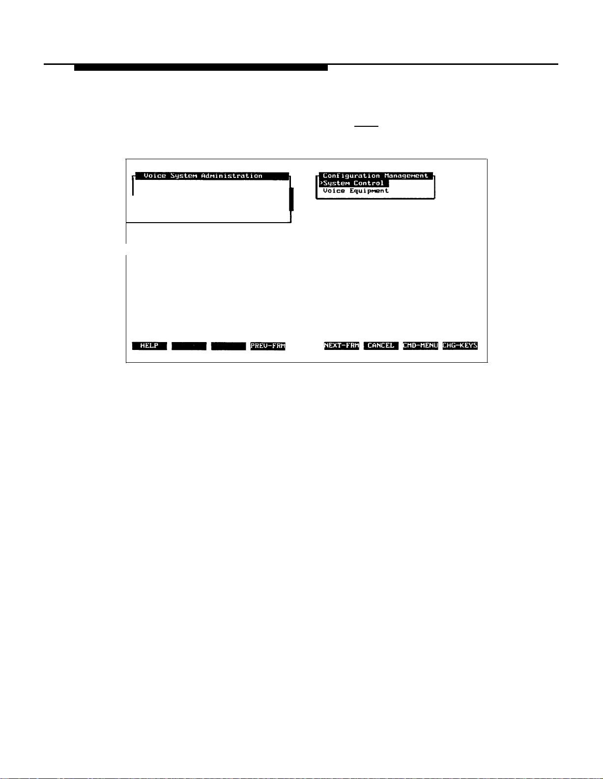
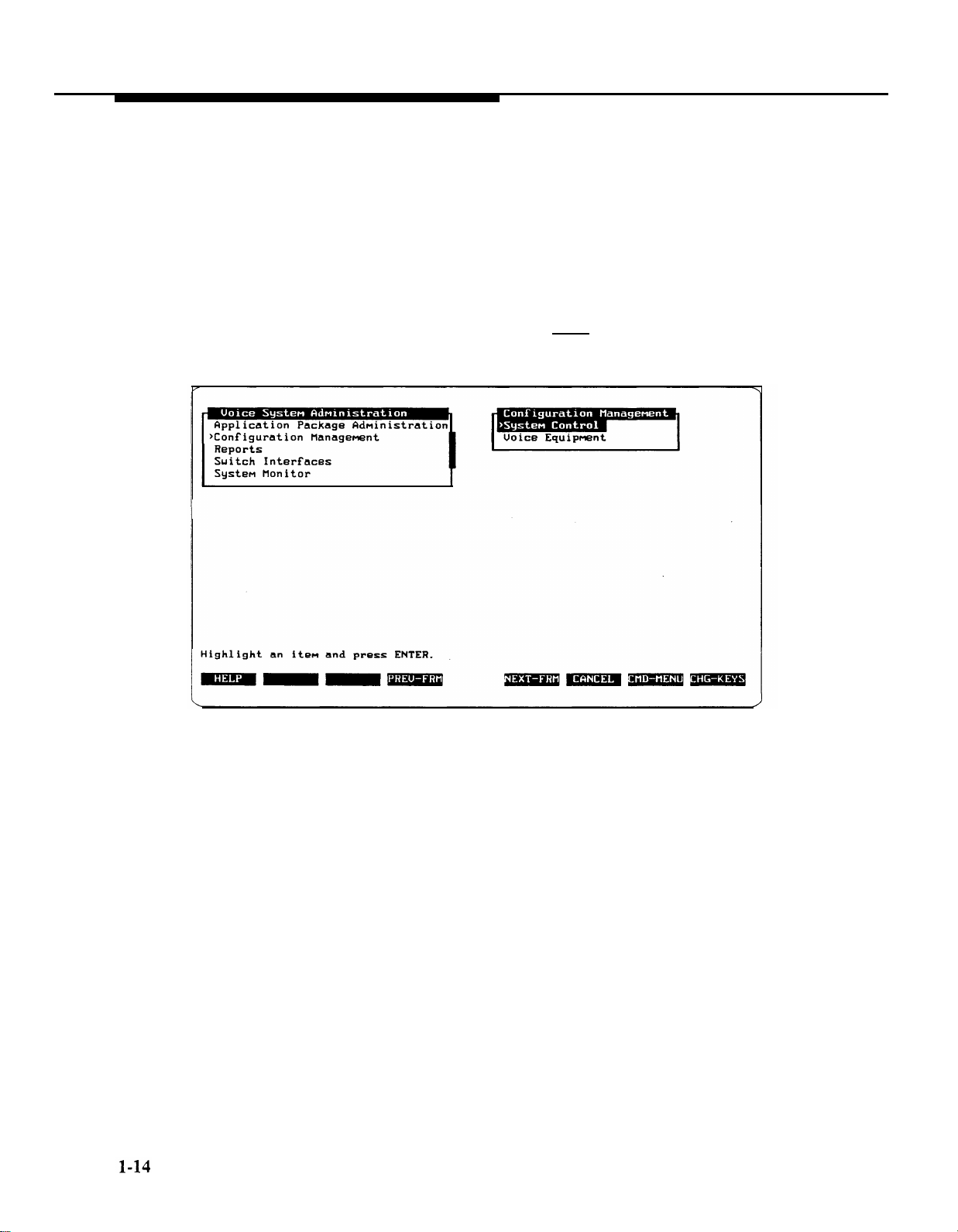
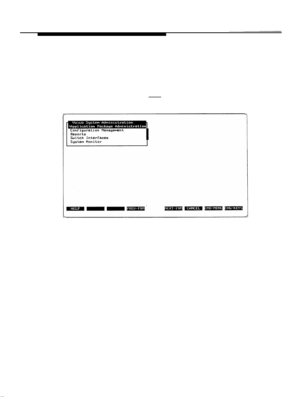
3.
At the Voice System Administration menu, move the cursor to
Configuration Management
— The Configuration Management menu appears.
Replication Package Administration
>Configuration Management
Reports
Switch Interfaces
System Monitor
I
Highlight an item and press ENTER,
and press (Enter).
4.
Continue with Entering the Channel Assignments for Testing.
1-6
Page 17
Overview and Testing
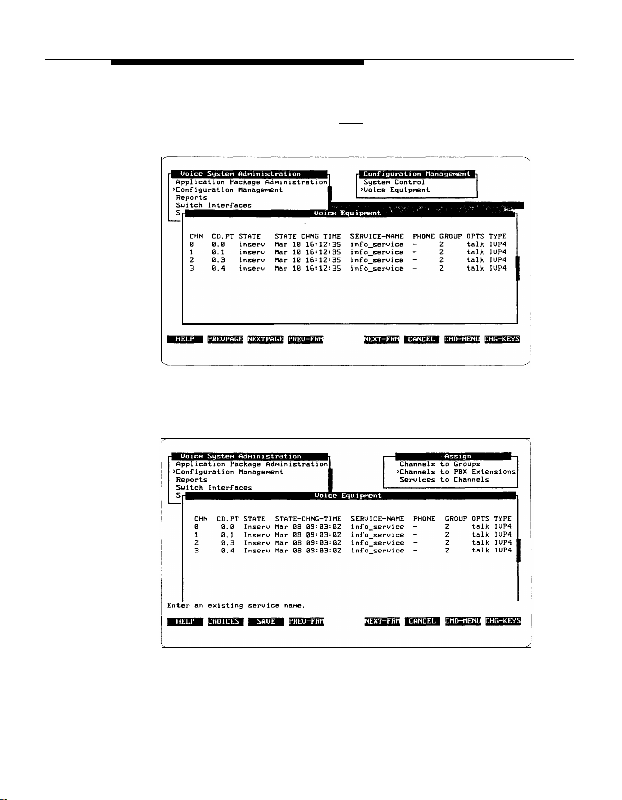
Entering the Channel Assignments for Testing
To enter the channel assignments, follow these steps:
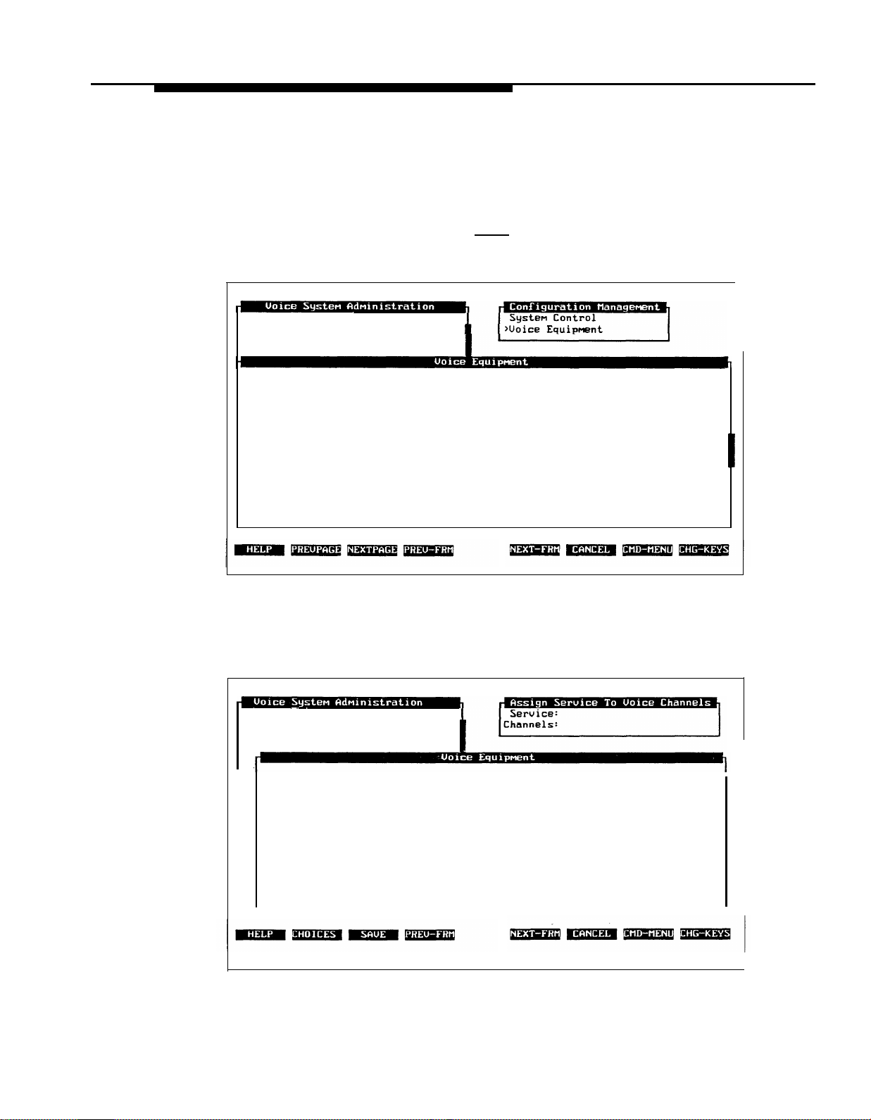
1.
At the Configuration Management menu, move the cursor to
Voice Equipment
— The Voice Equipment window appears.
Application Package Administration
>Configuration Management
Reports
Switch Interfaces
and press (Enter).
CHN CD. PT STATE
Ø
Ø.Ø Manoos Jul 29 14:55:35 -
1
Ø.1 Manoos Jul 29 14:55:35 -
2
Ø.3 Manoos Jul 29 14:55:35 -
3
Ø.4 Manoos Jul 29 14:55:35 -
2.
Press [F8] (CHG-KEYS).
Press [F3] (ASSIGN).
3.
STATE-CHNG-TIME SERVICE-NAME PHONE GROUP OPTS TYPE
2
2
2
2
— The Assign Service to Voice Channels form appears.
Application Package Administration
>Configuration Management
Reports
Switch Interfaces
S
—
CHN CD.PT STATE STATE-CHNG-TIME SERVICE-NAME PHONE GROUP OPTS TYPE
Ø
Ø.Ø Manoos Mar Ø8 Ø9:Ø3:Ø2 -
1
Ø.1 Manoos Mar Ø8 Ø9:Ø3:Ø2 -
2
Ø.3 Manoos Mar Ø8 Ø9:Ø3:Ø2 -
3
Ø.4 Manoos Mar Ø8 Ø9:Ø3:Ø2 -
2
2
2
2
talk IVP4
talk IVP4
talk IVP4
talk IVP4
talk IVP4
talk IVP4
talk IVP4
talk IVP4
Enter an existing service name.
1-7
Page 18

Overview and Testing
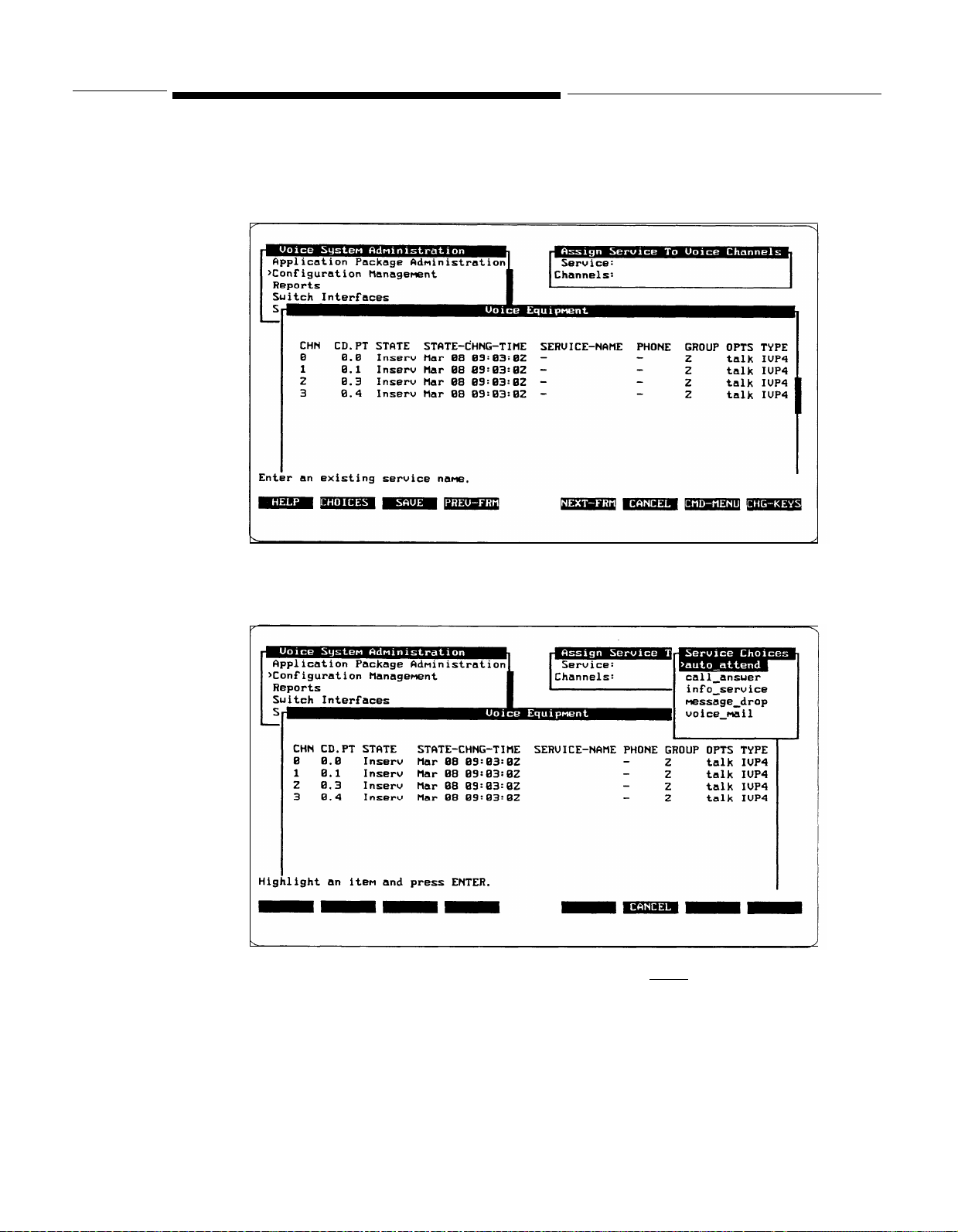
4.
Move the
5.
Press [F2] (CHOICES).
— The Service Choices window appears.
Application Package Administration
>Configuration Management
Reports
Switch Interfaces
s
CHN CD.PT STATE STATE-CHNG-TITLE SERVICE-NAME PHONE GROUP OPTS TYPE
Ø
Ø.Ø Manoos
Ø.1 Manoos
1
Ø.3
2
Ø.4 Manoos
3
Highlight an item and press ENTER.
cursor to the
Mar Ø8 Ø9:Ø3:Ø2
Manoos
Mar Ø8 Ø9:Ø3:Ø2
Mar Ø8 Ø9:Ø3:Ø2
Mar Ø8 Ø9:Ø3:Ø2
Service:
field.
message_drop
2
talk IVP4
2
talk IVP4
2
talk IVP4
2
talk IVP4
Move the cursor to
6.
— The service is filled in. The Service Choices window closes.
info_service
and press (Enter).
1-8
Page 19
Overview and Testing
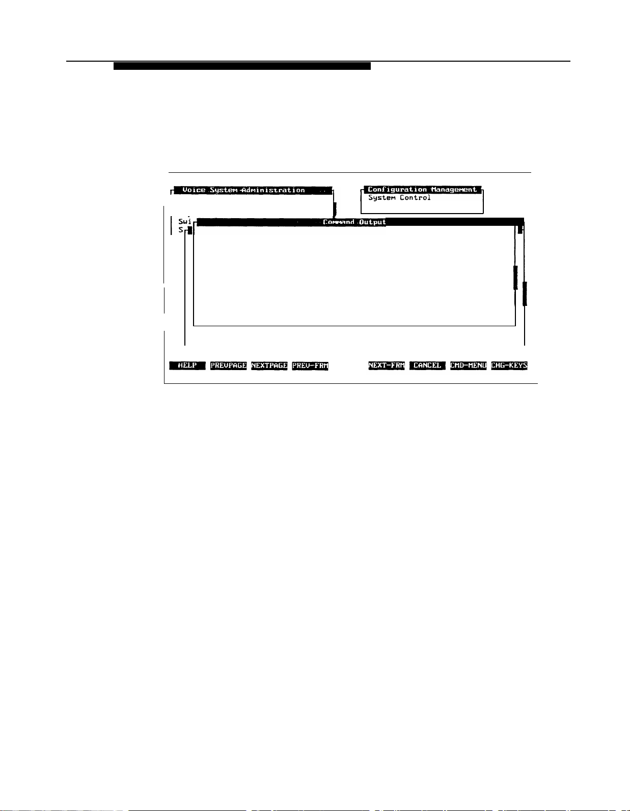
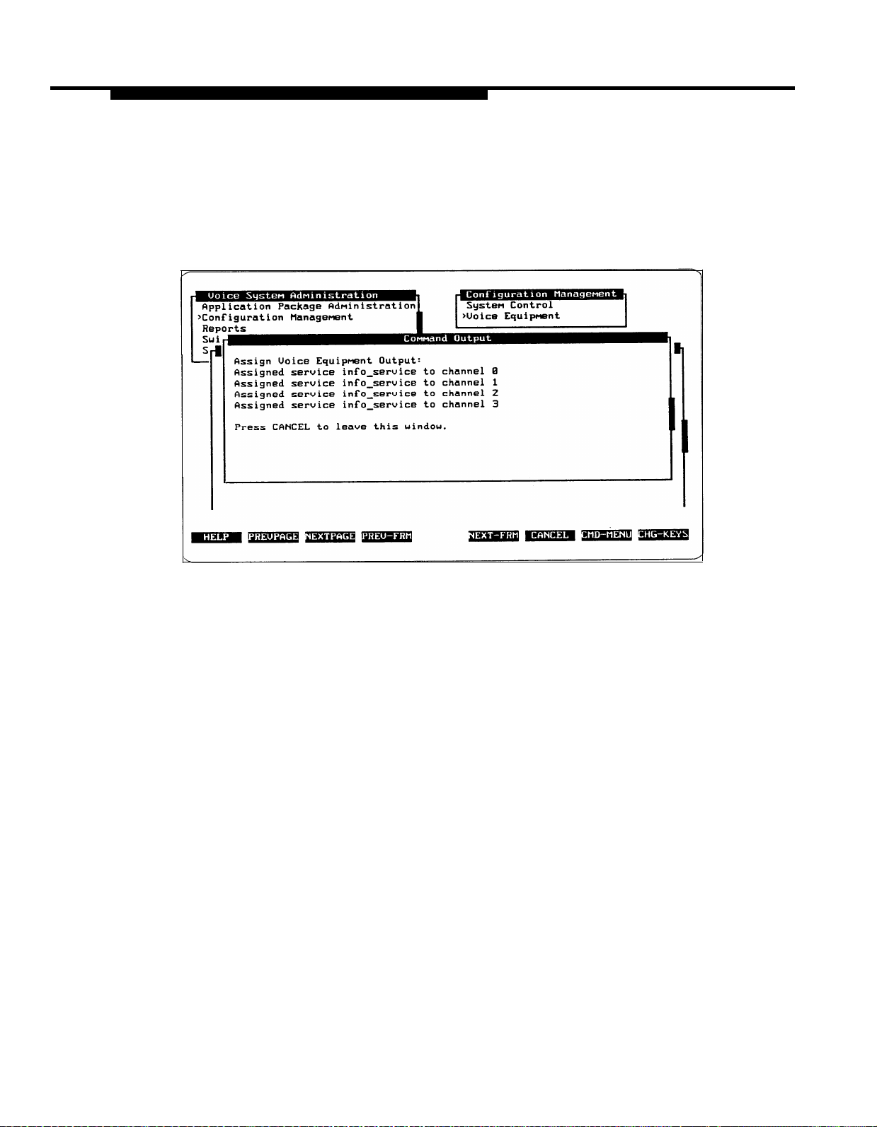
7.
Move the cursor to the
[F3] (SAVE).
— The information is entered, the Assign Service to Voice Channels
Channels:
field. Type
all
and press
form closes, and a Command Output window appears.
Application Package Administration
>Configuration Management
Reports
I
Assign Voice Equipment Output:
Assigned service info_service to channel Ø
Assigned service info_service to channel 1
Assigned service info_servi
Assigned service info_servi
Press CANCEL to leave this
Press [F6] (CANCEL) to close the Command Output window and return to
8.
ce to channel 2
ce to channel 3
window.
>Voice Equipment
the Voice Equipment window.
1-9
Page 20
Overview and Testing
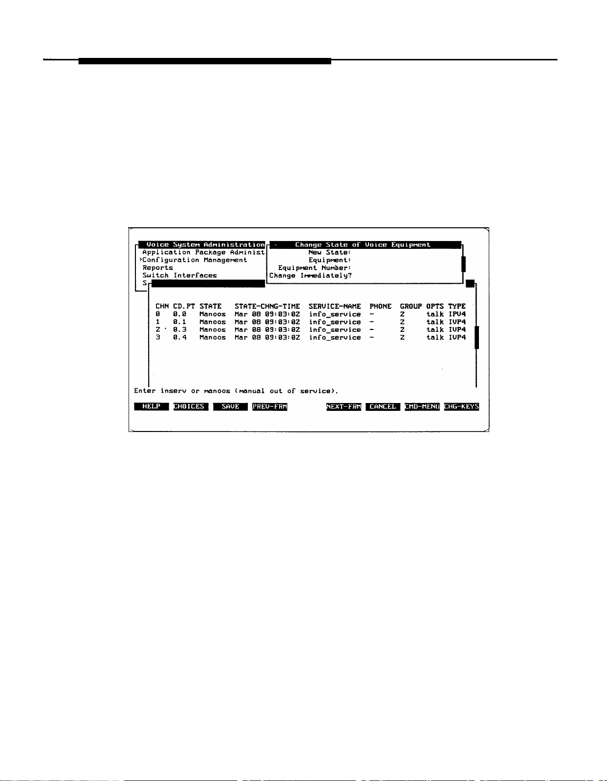
Placing All Channels In Service for Testing
In the Voice Equipment window, all channels should show the INSERV state. If
the status of any of the channels does not appear as INSERV, follow these steps:
1.
From the Voice Equipment
window, press [F8]
alternate key labels.
2.
Press [F2] (CHGSTATE).
— The Change State of Voice Equipment form appears.
(CHG-KEYS) to display the
1-10
Page 21
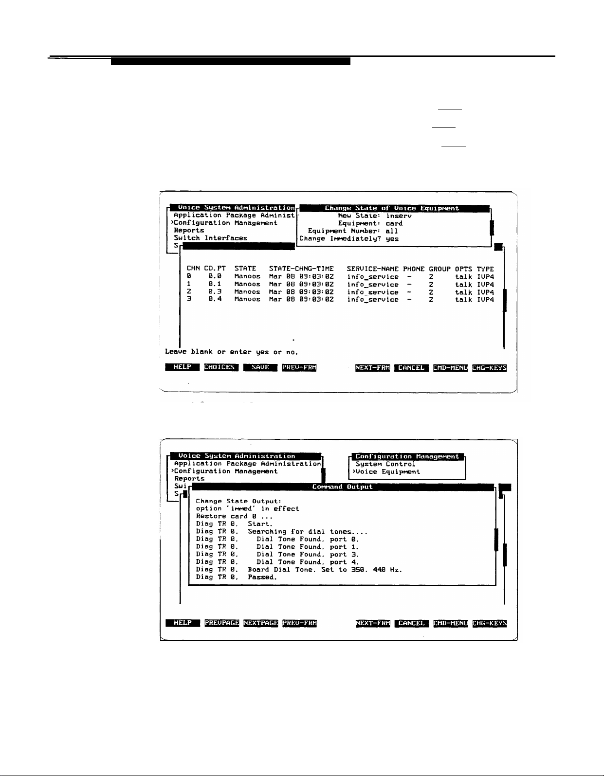
Overview and Testing
In the
3.
4.
In the
In the
5.
6.
In the
[F3] (SAVE).
New State:
Equipment:
Equipment Number:
Change Immediately?
field, enter
field, enter
field, enter
inserv
card
or
field, enter
or i and press (Enter).
ca
and press (Enter).
all
and press (Enter).
yes
or y and press
A Command Output window appears to inform you that the state has been
changed.
1
1-11
Page 22
Overview and Testing
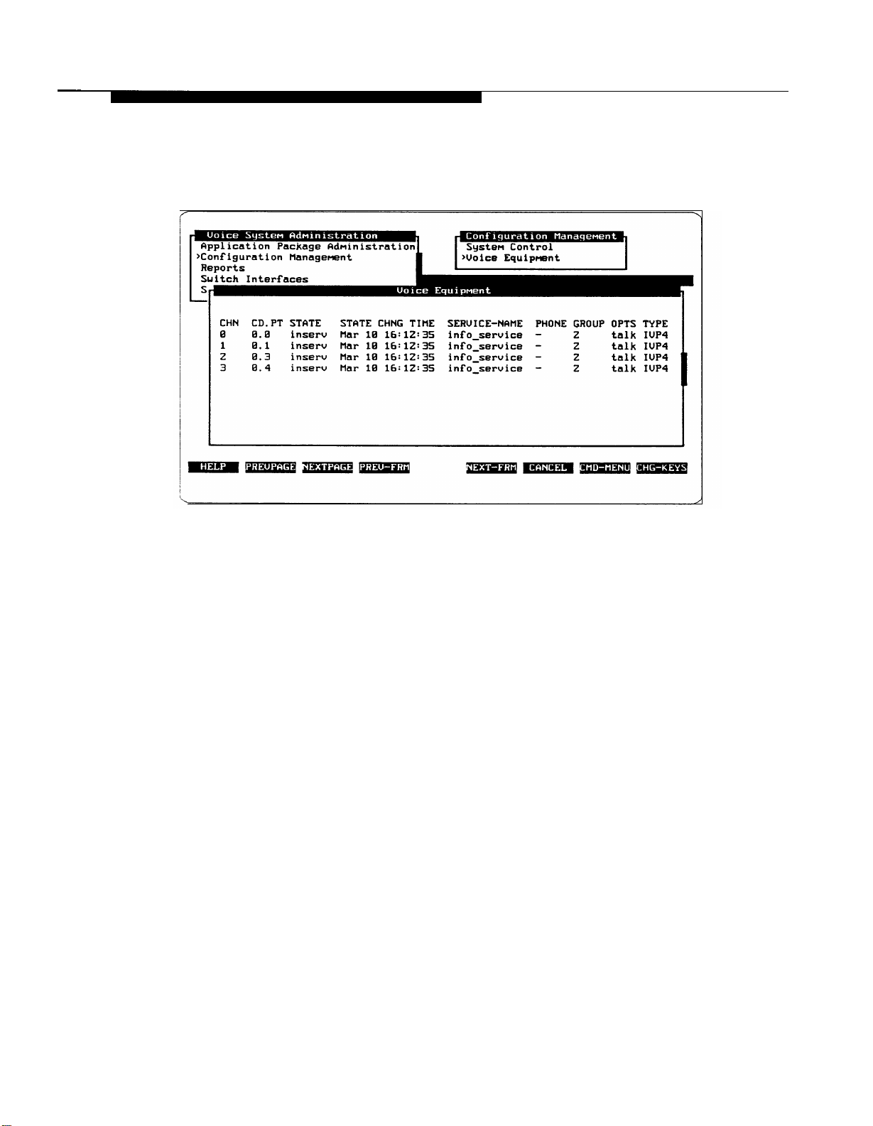
7.
Press [F6] (CANCEL) to continue.
— The Voice Equipment window reappears.
Verify that all channels now show the lNSERV state.
8.
— lf any channel shows the FOOS (Facility Out Of Service) state,
verify that each of the analog ports is connected.
Press [F6] (CANCEL) twice to return to the Voice System Administration
9.
menu.
1-12
Page 23

Overview and Testing
Verifying Extensions
To verify the extensions assigned to AUDIX Voice Power channels, follow these
steps:
1.
At the Voice System Administration menu, select
press (Enter).
— The Voice Channel Monitor window appears.
System Monitor
and
2.
Dial an extension connected to one of the AUDIX Voice Power analog
channels.
— You hear the default Information Announcement greeting.
— The status of the extension changes from “On Hook” to “Talking.”
Watch the Voice Channel Monitor window to see which channel answers
3.
the call.
Verify that the extension you dialed corresponds to the channel that
4.
answered. (If a different channel answered, record the change on FORM A
in the Planning Guide. )
Repeat Steps 2 through 4 until all extensions have been verified.
5.
If the extension assignments do not match those already recorded on FORM
A
in
the Planning Guide, you may either change the connections between the IVP4
boards and the wall outlet jacks, or you may notify the Switch Administrator of the
changed assignments. The optimum course of action depends on whether the
Switch Administrator has already made use of the extension assignments for the
rest of the administration that must be done on the switch side.
1-13
Page 24
Overview and Testing
Mapping the Phone Extensions to Channels (Integrated Only)
For the System 75 or DEFINITY G1 (integrated systems only), the phone
extensions must be mapped to the channels. The testing you performed
previously has determined this mapping, and the mapping has been entered on
FORM A in the Planning Guide. To enter this mapping into the AUDIX Voice
Power system, follow these steps:
1.
At the Voice System Administration menu, move the cursor to
Configuration Management
— The Configuration Management menu appears.
and press (Enter).
I
Page 25
Overview and Testing
2.
At the Configuration Management menu, move the cursor to
Voice Equipment
— The Voice Equipment window appears.
and press (Enter).
3.
At the Voice Equipment window, press [F8] (CHG-KEYS).
4.
Press [F3] (ASSIGN).
— The Assign form appears.
1-15
Page 26

Overview and Testing
5.
At the Assign form, move the cursor to
and press (Enter).
— The Channel to PBX Extension form appears.
Channel to PBX Extension
6.
Enter the extension number and press (Enter).
— The cursor moves to the Channel: field.
7.
Enter the channel number and press (Enter).
1-16
Page 27

Overview and Testing
Press [F3] (SAVE).
8.
— The information is entered and an Information window appears.
— Press (Enter) to close the lnformation window and return to the
Channel to PBX Extension form.
Repeat Steps 6 through 8 until extension numbers have been assigned to
9.
all the voice channels.
10.
Press [F6] (CANCEL) repeatedly to return to the Voice System
Administration menu.
Page 28

AUDIX Voice Power
Initial Implementation
Assigning Services to Channels
Integrated Systems
2
Integrated systems indicate to AUDIX Voice Power whether a call is direct
coverage. Channels that are assigned either Call Answer or Voice Mail get
Voice Mail for direct calls and Call Answer for coverage calls. To use a
channel for both Call Answer and Voice Mail, the channel should be assigned
.
Call Answer.
Table
2-1
shows what service a call receives, depending on what service is
assigned to the channel, and whether the call is direct or coverage.
Table
2-1.
Assigned Service Direct Call
Auto Attendant
Call Answer Voice Mail Call Answer
Voice Mail Voice Mail
Message Drop Message Drop
Information Information
If there are not enough channels to dedicate some to Voice Mail, the available
channels can be divided between Call Answer and Automated Attendant.
Actual Service Provided on Integrated Systems
Actual Service
Coverage Call
Auto Attendant
Auto Attendant
Call Answer
Message Drop
Information
2-1
Page 29

AUDIX Voice Power Initial Implementation
Non-Integrated Systems
Table
2-2
shows what service a call receives depending on what service is
assigned for non-integrated systems.
Table 2-2.
Actual Service Provided on Non-Integrated Systems
Assigned Service
Auto Attendant
Call Answer
Voice Mail
Message Drop
Information
Actual Service
Auto Attendant
Call Answer
Voice Mail
Message Drop
Information
Subscribers can reach Voice Mail from either Call Answer or Automated
Attendant by dialing
2-2
Page 30

AUDIX Voice Power Initial Implementation
Entering Service Assignments
Using the information in Table
2-1
or Table 2-2, make any necessary adjustments
to FORM A in the Planning Guide.
NOTE:
For Message Waiting Lamps to work, Channel 0 must be assigned
Call Answer, Voice Mail, or Automated Attendant. Call Answer is
recommended.
When
FORM A is complete and has been reviewed, enter the service assignment
information into AUDIX Voice Power. To enter this information, follow these-steps:
1.
Log into the system as
—
The User Login menu appears.
2.
At the User Login menu, move the cursor to
Administration
audix.
Voice System
and press (Enter).
— The Voice System Administration menu appears.
2-3
Page 31

AUDIX Voice Power Initial Implementation
At the Voice System Administration menu, move the cursor to
3.
Configuration Management
— The Configuration Management menu appears.
and press (Enter).
4. At the Configuration Management menu, move the cursor to
Voice Equipment and press (Enter).
— The Voice Equipment window appears.
Press [F8] (CHG-KEYS).
5.
2-4
Page 32
AUDIX Voice Power Initial Implementation
6.
Press [F3] (ASSIGN).
— The Assign Service to Voice Channels form appears.
7.
At the
Service:
field, press [F2] (CHOICES).
— The Service Choices window appears.
8.
Move the cursor to the desired service and press (Enter).
—The service is filled in and the Service Choices window closes.
Move the cursor to the
9.
Channels:
field. Enter a channel number from
0 to 11, a range of channel numbers with the starting and ending channel
numbers separated by a dash, or a list of channel numbers (separated by
commas) and/or ranges, or “all”.
2-5
Page 33
AUDIX Voice Power Initial Implementation
10.
Press [F3] (SAVE).
—
The information is entered, the Assign Service to Voice Channels
form closes, and a Command Output window appears.
11.
Press [F6] (CANCEL) to close the Command Output window and return to
the Voice Equipment window.
12.
Reopen the Assign Service to Voice Channels form by pressing
[F8] (CHG-KEYS) and then pressing [F3] (ASSIGN) and repeat Steps 7
.
through 11 until services have been assigned to all voice channels.
13.
Press [F6] (CANCEL) repeatedly to return to the Voice System
Administration menu.
Changing Service Assignments
To change service assignments, use the above procedure. The new assignments
will
replace the old assignments. To unassign a channel, press
[F8] (CHG-KEYS) and then press [F4] (UNASSIGN). The Unassign Service
From Voice Channel form appears. Enter the channel number(s) to be
unassigned, and press [F3] (SAVE). Channelsshould not beleftunassigned.’ln
most cases, an unassigned channel results in loss of system capacity. Also, a call
to an unassigned channel will result in an Event Log error message.
2-6
Page 34

AUDIX Voice Power Initial Implementation
Switch Interface Administration Parameters
Some specific parameters are necessary to tell AUDIX Voice Power how to
communicate with the telephone switch. For convenience, these parameters are
collected on FORM B in the Planning Guide. A sample is explained below.
FORM B
Switch Interface Administration
Switchhook Flash Duration
Wink Disconnect Interval
Signaling Type
The contents of each field should be:
■
Switchhook Flash Duration
milliseconds that the switch recognizes as a transfer request. The
range is 300 to 1550 milliseconds. The default is
■
Wink Disconnect Interval
that the switch recognizes as a disconnect request. The range is 300 to
800 milliseconds. The default is
specifies the on-hook duration in
.
specifies the on-hook duration in milliseconds
300
milliseconds.
I
I
I
600
milliseconds,
■
Signaling Type
signaling is used. The default is
Changing Switch Interface Parameters
The switch interface parameters should not be changed from the values specified
above. If for some reason they must be changed, enter the default values shown
above. The new values will replace the old values,
specifies whether Touch-Tone (TT) or dial-pulse (DP)
TT.
2-7
Page 35
AUDIX Voice Power Initial Implementation
You should not need to change any of the switch interface parameters. However,
if you need to change any of these parameters, follow these steps:
1.
Log into the system as
audix.
— The User Login menu appears.
2.
At the User Login menu, move the cursor to
Administration
and press (Enter).
— The Voice System Administration menu appears.
Voice System
2-8
Page 36
AUDIX Voice Power Initial Implementation
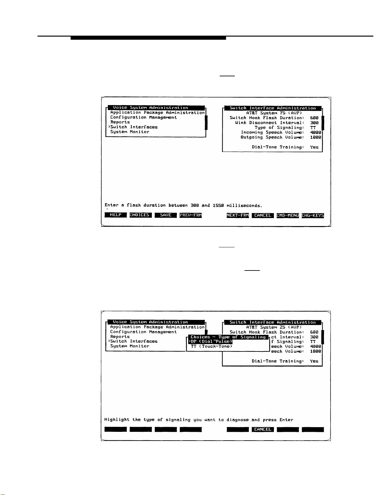
3.
At the Voice System Administration menu, move the cursor to
Switch Interfaces
and press (Enter).
— The Switch Interface Administration form appears.
I
4.
Move the cursor to the
Switch Hook Flash Duration:
field,
number from FORM B, and press (Enter).
—The cursor moves to the
5.
Enter the number from FORM B and press (Enter),
Wink
Disconnect Interval: field.
—The cursor moves to the Type of signaling: field.
6.
Press [F2] (CHOICES) to bring up the Choices -Type of Signaling
window.
enter the
2-9
Page 37
AUDIX Voice Power Initial Implementation
7.
Move the cursor to the type of signaling specified on FORM B and
press (Enter).
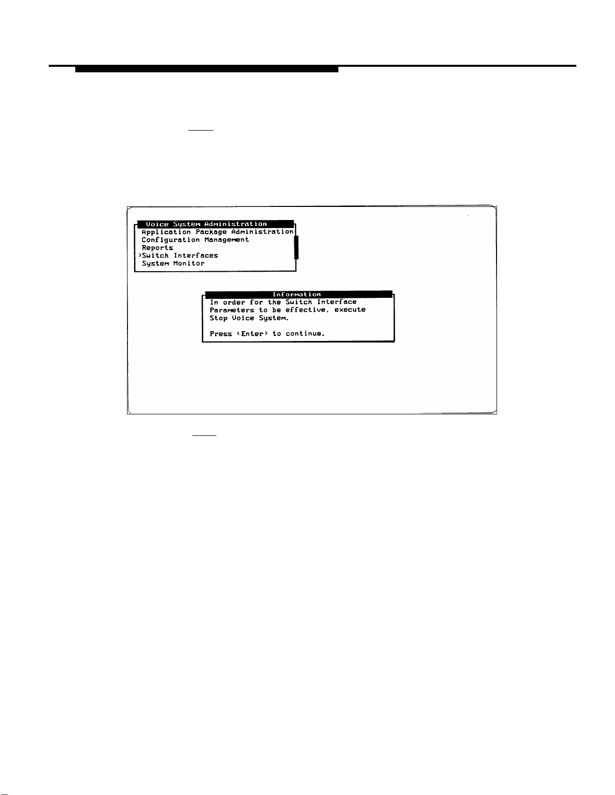
Press [F3] (SAVE).
8.
—
The Switch Interface Administration form closes and a message
appears asking the user to stop the system for the changes to
take effect.
Press (Enter) to return to the Voice System Administration menu.
9.
—
Follow the procedures in the AT&T AUDIX™ Voice Power System
Manager’s Guide for stopping and starting AUDIX Voice Power.
2-10
Page 38

AUDIX Voice Power Initial Implementation
Verifying System Parameters
After the first two groups of system parameters (Voice Mail and Automated
Attendant parameters) have been determined and entered on FORM C, review
them. Then add the Message Waiting Lamp parameters to the third section of
FORM C in the Planning Guide and enter the parameters into the AUDIX Voice
Power system.
You will need two pieces of information:
■
whether or not the message waiting lamps are to be used
■
the System 75 or DEFINITY G1 message waiting lamp codes if they have
been changed from the default
Verifying Message Waiting Lamp Parameters
Message Waiting Lamp parameters affect only the operation of message waiting
lamps. The following parameters are available:
■
Code to Light
to the switch to light the message waiting lamp. Enter the value found on
the Feature Access Code form or leave the field blank if message waiting
lamps will not be used.
specifies the internal code that AUDIX Voice Power sends
■
Code to Extinguish
specifies the internal code that AUDIX Voice Power
sends to the switch to extinguish the message waiting lamp. Enter the
value found on the Feature Access Code form or leave the field blank if
message waiting lamps will not be used.
■
Refresh
refreshed at predetermined intervals. Enter
are used, or
indicates whether you wish to have message waiting lamps
y
if message waiting lamps
n
if message waiting lamps will not be used.
Page 39

AUDIX Voice Power Initial Implementation
Displaying Feature Access Codes
The codes used by System 75 or DEFINITY G1 to activate/deactivate the
Message Waiting Lamp should be verified by logging into the switch and entering
display
feature-access-codes
Page 2 of the Feature Access Code form lists the codes needed to
activate/deactivate the Message Waiting Lamp. (See Figure
fields in the Feature Access Code form should be compared against FORM C. If
necessary, update FORM C in the Planning Guide to reflect the values displayed
on the Feature Access Code form.
■
Leave Word Calling Send a Message: —Use this value for the
AUDIX Voice Power System Parameter
■
Leave Word Calling Cancel a Message: — Use this value for the
AUDIX Voice Power System Parameter
on the command line.
Code to Light.
Code to Extinguish.
2-1.)
The following
FEATURE
Group Control Restrict Activation: 125
Hunt Group Busy Activation: *8
Leave Word Calling Message Retrieval Lock: *1
Leave Word Calling Message Retrieval Unlock: #1
Voice Coverage Message Retrieval Access Code: 140
Voice Principal Message Retrieval Access Code: 141
Figure
2-1.
Last Number Dialed Access Code: *9
Leave Word Calling Send a Message: *4
Leave Word Calling Cancel a Message: #4
Print Messages Access Code:
Priority Calling Access Code: *7
Program Access Code: *0
Send All Calls Activation: *3
SMDR Account Code Access Code: *6
Transfer Into AUDIX: 123
Trunk Answer Any Station Access Code:
User Control Restrict Activation: 105
System 75/DEFINITY
ACCESS CODE (FAC)
G1
Page
2 of 3
Deactivation: 126
Deactivation: #8
Deactivation: #3
Deactivation: 106
Feature Access Code Form (Page 2)
2-12
Page 40

AUDIX Voice Power Initial Implementation
FORM C
System Parameter Administration
Voice Mail Parameters
System Operator. Extension:
Pause for Touch-Tone Input:
Maximum Extension Length:
Transfer to Subscribers Only?:
System Mode of Addressing:
Maximum Message Length:
General Mailbox Owner Extension:
Enable General Mailbox for Call Answer?:
Allow Voice Mail/Call Answer Transfers?:
Automated Attendant Parameters
Touch-Tone Gate Active?:
Auto Attendant Time-out Action:
Day:_
Day:_
Auto Attendant Menu Plays:
Fax Transfer Number:
Present Options before leaving Message?:
sec
sec
Night:_
Night:_
Message Waiting Lamp Parameters
Code to Light:
Entering System Parameters
To enter the system parameters, follow the instructions in Chapter 3 of the
AT&T AUDIX™ Voice Power System Manager’s Guide.
Code to Extinguish:
Refresh?:
2-13
Page 41

System 75 and DEFINITY G1 Initial Implementation
The information in this section is intended to help you and the System 75 or
DEFINITY G1 Switch Administrator work together to administer the switch and
meet the specific requirements on the switch for your AUDIX Voice Power
system. To complete these tasks, you will need to access information regarding
switch administration, and use the accompanying forms for the switch.
AUDIX Voice Power is designed to operate with a System 75 or DEFINITY G1
Private Branch Exchange (PBX) using analog lines. T
AUDIX Voice Power, the PBX also requires a connection from a TN-754 board
to the AUDIX Voice Power DCP board.
Verifying Software Release
Before beginning the switch administration, verify the system software release.
■
If the PBX is a System 75 with release R1V3 software, verify that software
vintage 17091 (Issue 1.7) or greater has been installed.
■
If the PBX is a DEFINITY G1, verify that software Issue 4.0 or greater has
been installed.
If you have an R1V3 or G1 and you do not have the proper software, DO NOT
proceed with the switch administration. Instead ask your AT&T Representative to
contact the AT&T Sales and Technical Response Center at 1-800-521-7872 to
obtain the correct software. Once it has been installed, you may proceed with the
switch administrate ion.
O
integrate the PBX with
3-1
Page 42

System 75 and DEFINITY G1 Initial Implementation
Release R1V1 and R1V2 Software Limitations
The R1V1 and R1V2 versions of System
the operation of AUDIX Voice Power. One of these limitations includes possible
effects of the Music On Hold feature for all R1V1 and R1V2 systems.
The other limitations apply only to integrated systems. For R1V1, the limitations
include the inability of attendants to access AUDIX Voice Power via the DCP line,
the inability of all subscribers to access AUDIX Voice Power via the DCP line to
retrieve messages, and a less-reliable interface between the switch and the
AUDIX Voice Power system. For R1V2 systems, the limitations are related to
the inability of the attendant to access AUDIX Voice Power via the DCP line.
75
have several limitations that affect
Music On Hold
If your switch is configured for Music On Hold, you must upgrade the switch to
R1V3, R1V4, or G1. Otherwise, callers will hear and be confused by several
seconds of music prior to hearing the greeting from the AUDIX Voice Power
system that they were expecting.
Accessing the DCP Extension (R1V1)
Callers cannot access voice mail by calling the DCP extension. The DCP
interface is used only for the Call Answer Service. A hunt group of one or more
channels configured for the Voice Mail Service must be set up for access to voice
mail. This is non-integrated Voice Mail Service. Subscribers must enter their
extension as well as their password to retrieve their messages. The Class of
Restriction feature of System 75 must be used to prevent subscriber access to
the DCP number. However, subscribers must have access to the Voice Mail hunt
group.
3-2
AUDIX Voice Power software that interfaces to System 75 R1V1 software
transfers calls from the DCP line to one of its analog lines. The System 75
software does not allow calls from an attendant console to be transferred.
Because of this, an attendant cannot transfer a caller to a subscriber and wait for
AUDIX Voice Power to provide Call Answer Service for the caller. The attendant
must either drop the call after the transfer is performed, or return to the caller
when the ringing stops. In addition, if the attendant wants to leave a message for
a subscriber, he or she must call a separate group of one or more channels
configured for the special service “attendant_ca” which provides non-integrated
Call Answer Service. The attendant must enter the extension of the person
receiving the message.
Page 43

System 75 and DEFINITY G1 Initial Implementation
Accessing the DCP Extension (R1V2)
AUDIX Voice Power software that interfaces to System 75 R1V2 software
transfers calls from the DCP line to one of its analog lines. The System 75
software does not allow calls from an attendant console to be transferred.
Because of this, an attendant cannot transfer a caller to a subscriber and wait for
AUDIX Voice Power to provide Call Answer Service for the caller. The attendant
must either drop the call after the transfer is performed, or return to the caller
when the ringing stops. In addition, if the attendant wants to leave a message
for a subscriber, he or she must call a separate group of one or more channels
configured for the special service “attendant_ca” which provides non-integrated
Call Answer Service. The attendant must enter the extension of the person
receiving the message.
Also, attendants cannot access the Voice Mail Service by calling the DCP
number. A hunt group of one or more channels configured for “voice_mail” must
be set up to allow attendants access to voice mail. This is non-integrated Voice
Mail. Attendants must enter their extension as well as their password to retrieve
their messages. The Class of Restriction feature of the System 75 must be used
to prevent attendant access to the DCP number. However, attendants must have
access to the Voice Mail hunt group.
.
Attendants may access their messages via the “attendant_ca” service by pressing
This would mean that only one additional set of channels is needed by
attendants to access messages.
Stations Supported (R1V1)
The R1V1 release of the System 75 software does not support the PC type
of digital station that is specified in the documentation. Only two choices are
provided: 7405D and 7403D. Neither of these types provides as reliable an
interlace as the PC type, This results in a significant number of calls that must
be handled by an attendant, since AUDIX Voice Power sometimes receives
unusable information from the switch. The rate at which this occurs can be
monitored via the “Bad Switch Info” category of the Phone Line Usage Report.
Upgrade Installation
If you are
integrated system, the switch integration software must be reloaded. Refer to
Chapter 3 in the AT&T AUDIX™ Voice Power Installation and Maintenance Guide
for the procedures to install the switch integration software.
upgrading the
version of the switch being used and have an
3-3
Page 44

System 75 and DEFINITY G1 Initial Implementation
AUDIX Voice Power Checklist
When administering the switch, you will perform the following tasks:
■
Configure Class of Restrictions (CORs) (Integrated only)
■
Verify Analog Channels for connection to AUDIX Voice Power
■
Verify DCP Extension (Integrated only)
■
Administer Hunt Groups for multiple channels of the same service
Services that may require hunt groups are:
— Automated Attendant
— Information Service
— Message Drop Service
— Call Answer on non-integrated configurations
— Voice Mail on non-integrated configurations
■
Administer Call Coverage Paths
■
Perform Subscriber Administration
■
Verify Trunk Name Administration (Integrated only)
3-4
Page 45

System
75 and DEFINITY G1 Initial Implementation
Assigning Class of Restrictions
(Integrated Only)
Figures
the COR administration, we recommend setting
3-1, 3-2,
and 3-3 depict the Class of Restriction (COR) form. To simplify
up the three CORs as shown in
the following list, but if they have already been assigned, you can use any
available COR.
■ COR 1 - Subscribers
CLASS OF RESTRICTION
COR Number: 1
Partitioned Group Number: 1
Service Observing? n
Priority Queueing? n
CALLING PERMISSION (Enter “y” to grant permission to call specified COR)
o? y
1?y 9? y 17?y
2? y
3? y
4? y
5? y
6? y
7? y
8? n
10?y 18?y
11?y 19?y
12?y
13?y
14?y
15?y
APLT y Calling Party Restriction: none
Called Party Restriction: none
Forced Entry of Account Codes? n
Facility Access Trunk Test? n
16?y
20? y 28? y 36? y
21?y
22? y 30? y
23? y
24? y 32? y
25? y
26? y
27? y
29? y
31?y
33? y
34? y
35? y
37? y
38? y 46? y
39? y
40? y 48? y 56? y
41?y
42? y 50? y 58? y
43? y
44? y
45? y 53? y
47? y
FRL: 7
49? y
51?y
52? y
54? y 62? y
55? y 63? y
57? y
59? y
60? y
61?y
Figure 3-1. System 75/DEFINITY G1 Class of Restriction Form COR 1
3-5
Page 46

System 75 and DEFINITY G1 Initial Implementation
■ COR 8- Voice Mail and Call Answer channels
CLASS OF RESTRICTION
COR Number: 8
Partitioned Group Number: 1
Service Observing? n
Priority Queueing? n
CALLING PERMISSION (Enter “y” to grant permission to call specified COR)
o? y
1?y 9? y 17?y
2? y
3? y
4? y
5? y
6? y
7? y
Figure 3-2.
8? n 16?n
I0?y
ll?y 19?y
12?y
13?y 21?y
14?y
l5?y
System 75/DEFINITY G1 Class of Restriction Form COR 8
APLT y
Forced Entry of Account Codes? n
24? y 32? y 40? y
25? y
18?y
20? y
22? y 30? y 38? y
23? y
26? y 34? y
27? y 35? y 43? y
28? y 36? y
29? y
31?y
Calling Party Restriction: none
Called Party Restriction: none
Facility Access Trunk Test? n
33? y
37? y 45? y 53? y
39? y 47? y 55? y
41?y
42? y
44? y 52? y 60? y
46? y 54? y
FRL: 7
48? y 56? y
49? y 57? y
50? y
51?y
58? y
59? y
61?y
62? y
63? y
3-6
Page 47

System 75 and DEFINITY G1 Initial Implementation
■ COR 16- DCP (PC/PBX) connection extension
CLASS OF RESTRICTION
COR
Number:16
Partitioned Group Number: 1
CALLING PERMISSION (Enter “y” to grant permission to call specified COR)
0? y
1?n
2? y
3? y
4? y
57 y
6? y
7? y
Figure 3-3.
Service Observing? n
Priority Queueing? n
8? y
9? y 17?y
l0?y 18?y
ll?y 19?y
12?y
13?y 21?y
14?y
15?y
System 75/DEFINITY G1 Class of Restriction Form COR 16
APLT y
Forced Entry of Account Codes? n
16?n
20? y 28? y 36? y
22? y 30? y 38? y
23? y
24? y 32? y
25? y 33? y
26? y 34? y
27? y
29? y 37? y
31?y
Calling Party Restriction: none
Called Party Restriction: none
Facility Access Trunk Test? n
40? y 48? y 56? y
41?y
42? y
35? y
39? y 47? y 55? y 63? y
43? y
44? y
45? y 53? y
46? y
FRL: 7
49? y 57? y
50? y 58? y
51?y
52? y
54? y 62? y
CORs are assigned so that the following can be accomplished:
■ Subscribers can call the extension numbers assigned to:
— Information
Service
59? y
60? y
61?y
— Automated Attendant
— Message Drop
— DCP (PC/PBX connection)
■ The DCP can call:
— Call Answer extension numbers
— Voice Mail extension numbers
The Voice Mail/Call Answer channels should be restricted so that they cannot call
themselves. On the System Administrator Terminal (SAT) for System 75, type
change
cor 8. (See Figure 3-2. ) Use (Enter) to tab to 8 and change y to
n. Press [F3] (ENTER) to enter the changes.
3-7
Page 48

System 75 and DEFINlTY G1 Initial Implementation
The DCP extension should be restricted so that it cannot call itself or subscriber
extensions. On the SAT, type
tab to 1 and 16, changing
change cor 16.
y
to
n.
Press [F3] (ENTER) to enter the changes.
Finally, the subscriber extensions should be restricted so that they cannot call the
Voice Mail/Call Answer ports directly. On the SAT, type
(See Figure 3-1.) Use (Enter) to tab to 8 and change
to enter the changes.
NOTE:
Any other CORs that have been administered on your switch need to be
changed so that they cannot call the Voice Mail/Call Answer channels
directly (Integrated only).
Verifying Analog Charnel Administration
Verify the following fields for each AUDIX Voice Power extension on FORM A
using the,
display station
command on the switch. (See Figure 3-4.)
(See Figure 3-3.) Use (Enter) to
change cor 1.
y
to
n.
Press [F3] (ENTER)
■ Type
■ Name
■ LWC Activation
■ LWC Reception
■ Call Waiting Indication
■
Att. Call Waiting Indication
■ COR (Integrated only)
3-8
Page 49

System 75 and DEFINITY G1 Initial Implementation
STATION
Extension: 25001
Type: 2500
Port: A0402 Security Code:
Name: call answer Coverage Path:
FEATURE OPTIONS
LWC Reception: ap-spe Headset? n Coverage Msg Retrieval? y
LWC Activation? y
Redirect Notification? y
Off Premise Station? n
Switchhook Flash? y Message Waiting Indicator:
ABBREVIATED
Lock Messages? n
Auto Answer? n Data Restriction? n
DIALING
COR: 8
COS: 1 Jack:
Tests? n Cable:
Call Waiting Indication? n
Att. Call Waiting Indication? n
Distinctive Audible Alert? y
Room:
List1: List2:
HOT LINE DESTINATION
Abbreviated Dialing List Number (From above 1, 2, or 3):
Dial Code:
List3:
Figure 3-4. System 75/DEFINITY G1 Display Station Form
(Voice Power Channel 1)
If any discrepancies are found, use the change station command and the
following procedure to make the appropriate changes:
1.
Enter
the extension.
2.
Enter
Type: as
3.
4.
Enter
Enter
Name:
COR
2500.
as
Get Voice Mail.
(Integrated only).
This is only necessary for Channel 0.
NOTE:
The recommended Voice Mail/Call Answer COR is
8 or whatever
COR was assigned in the previous section. For all other services,
the recommended COR is 1.
5.
Enter
LWC Activation? as yes.
3-9
Page 50

System 75 and DEFINITY G1 Initial Implementation
6.
Enter LWC
Reception:
Release Setting
according to the following table:
7.
Enter Call Waiting
Enter Att.
8.
Leave the remaining fields at default values. Repeat this procedure for each
extension assigned to an AUDIX Voice Power analog channel.
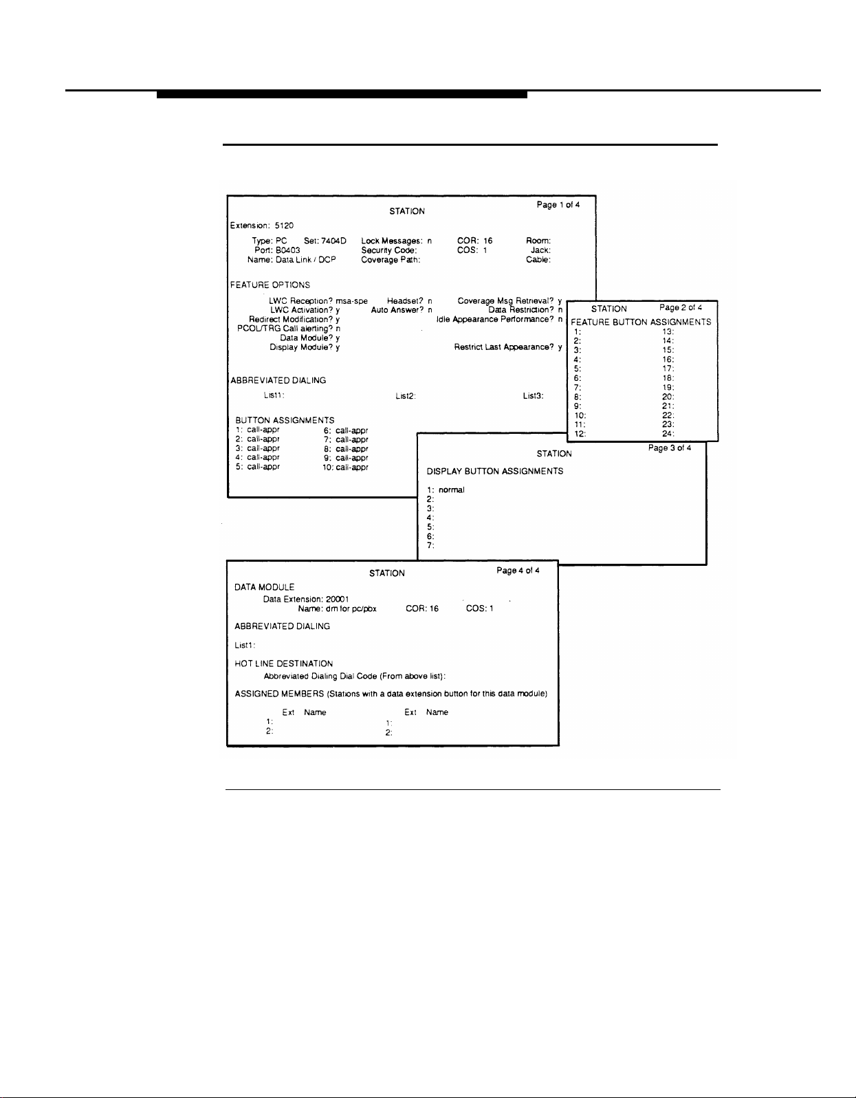
Configuring
DCP
(Integrated Only)
To integrate the switch to AUDIX Voice Power, a digital station must be
configured. See Figure 3-5.
Use the following procedure
(add station
1.
Enter
R1V1
R1V2 yes
R1V3
G1
Call Waiting Indication? as n.
Extensions
or
change
Type:
as
PC.
y
ap-spe
msa-spe
Indication? as n.
and the appropriate station command
station)
to configure the
DCP
extension:
NOTE:
If your switch is a R1V1 software vintage, the station type should be
assigned as a 7405D set.
2.
Enter
Set:
as
7404D.
Enter COR as 16 or whatever COR was assigned to the DCP connection
3.
extension. (See Figure 3-3.)
4.
Set
Restrict Last Appearance? to y.
Set all ten button assignments to call-appr.
5.
Enter normal for Button 1 under DISPLAY BUTTON ASSIGNMENTS
6.
(Page 3) or
7.
Set
Data Module?
FEATURE BUTTON ASSIGNMENTS
to
y.
(Page 2).
This data module is actually a dummy extension that will not be used for
AUDIX Voice Power. When assigning this extension, it is recommended
that you select an obscure extension that will not be needed in the future,
but which is a valid number in the dial plan.
3-10
Page 51
System
75 and DEFINITY G1 Initial Implementation
Figure 3-5.
System 75/DEFINITY G1 Display Station Command Form
for DCP Link
3-11
Page 52

System 75 and DEFINITY G1 Initial Implementation
Administering Hunt Groups
Hunt groups should be created when more than one extension number is
assigned to the same AUDIX Voice Power service. This allows the subscribers to
call a single number, and the group extension to access the service. (See Figures
3-6 and 3-7.)
Non-Integrated Mode
In the non-integrated mode, hunt groups should be used for all services. The Call
Answer hunt group number will be assigned as a coverage point in the coverage
path for AUDIX Voice Power subscribers to provide the AUDIX Voice Power Call
Answer Service.
Integrated Mode
In the
integrated mode, hunt groups can be used for all services except Voice
Mail and Call Answer. Hunt groups are not used for these two services because
the integration process automatically transfers calls to the Voice Mail and Call
Answer analog channels. The DCP Extension should be assigned as a coverage
point in the coverage path for AUDIX Voice Power subscribers to provide the Call
Answer Service.
3-12
Page 53

iSystem 75 and DEFINlTY G1 Initial Implementation
Creating Hunt Groups
To create a hunt group, use the
1.
Assign a group number between 1-100.
2.
Assign a group extension.
switch dial plan.
3.
Enter the extensions of the analog channels that you are assigning as
members of the hunt group on Page 2 of the hunt group form.
(See Figure 3-7.)
NOTE
When you enter the extension, the name is filled in automatically.
Group Number: 1
Group Name: auto attendant
Security Code:
Queue? y
Night Service Destination:
add hunt-group
command and:
This extension must be a valid extension in the
Page 1 of
5
HUNT GROUP
Group Extension: 30000 Group Type:
Coverage Path:
Message Center: none
ucd
COR: 1
ACD? n
Calls Warning Threshold:
Time Warning Threshold:
First Announcement Extension:
Figure 3-6.
Queue Length: 2
Hunt Group Form (Page 1)
Calls Warning Port:
Time Warning Port:
Announcement Delay
(sec):
3-13
Page 54

System
75 and DEFINITY G1 Initial Implementation
Page 2 of 5
HUNT GROUP
Group Number: 1
GROUP MEMBER ASSIGNMENTS
Ext
1: 25000 auto attendant
2: 25002 auto attendant
3:
4:
5:
6:
7:
8:
9:
10:
11:
12:
13:
Name
Figure 3-7. Hunt Group Form (Page 2)
Administering Call Coverage
Group Extension: 30000
Ext Name
14:
15:
16:
17:
18:
19:
20:
21:
22:
23:
24:
25:
26:
Group Type: ucd
Creating
3-14
AUDIX Voice Power can be administered as the first, second, or third point of call
coverage. (See Figure
In the non-integrated mode, the Call
3-8.)
Answer hunt group number should
be used
as the coverage point. In the integrated mode, the DCP extension number should
be used as the coverage point.
Coverage Paths
Use the add coverage path command. Inside and
administered identically. Typically, the number of rings
between 2 and 4.
outside calls should be
assigned should be
Page 55

System 75 and DEFINITY G1 Initial Implementation
Changing Coverage Paths
Use the change coverage path command to make the appropriate changes.
COVERAGE PATH
Coverage Path Number: 6
Next Path Number:
COVERAGE CRITERIA
Station/Group Status
Active?
Busy?
Don’t Answer?
SAC/Go to Cover?
COVERAGE POINTS
Point1: h7
Point2:
Inside Call
n
y
y y
n
y
Figure 3-8. Call Coverage Form
Performing Subscriber Administration
Page 1 of 1
Linkage:
Outside Call
n
y
Number of Rings: 2
n
y
Point3:
Verify the information for each subscriber on the switch who will be a subscriber
on the AUDIX Voice Power using the change station command. Assign each
station’s parameters as follows (see Figure 3-9):
1.
Verify that the
FORM D in the
2.
Enter the coverage path number which contains either the DCP extension
Name:
field exactly matches the name recorded on
Planning Guide. If not, change FORM D.
(for integrated systems) or the Call Answer Hunt Group extension
(for non-integrated systems).
3.
Enter 1 as the COR or whatever COR was assigned to Subscribers.
(Integrated only.) (See Figure 3-1.)
3-15
Page 56

System 75 and DEFINITY G1 Initial Implementation
4. Enter
LWC Reception?
according to the following table:
Release Setting
R1V1
y
R1V2 yes
R1V3
G1
ap-spe
msa-spe
WARNING:
DO NOT ASSIGN AS audix.
5. Assign
6. For single-line analog stations, set the
LWC Activation? as y.
to either
yes
or
led.
STATION
Message Waiting Indicator?
Page 1 of 1
Extension: 4488
Type: 2500
Port: A0906
Name: A. Subscriber
FEATURE OPTIONS
LWC Reception? msa-spe
LWC Activation ? y
Redirect Notification ? y
Off Premise Station? n
Switchhook Flash? y
ABBREVIATED DIALING
List1 :
HOT LINE DESTINATION
Abbreviated Dialing List Number (From above 1, 2, or 3):
Lock Messages: n
Security Code:
Coverage Path: 6
Headset? n
Auto Answer? n
List2:
Dial Code:
COR: 1
COS: 1
Tests? y
Coverage Msg Retrieval? y
Data Restriction? n
Call Waiting Indication? y
Att. Call Waiting Indication? y
Distinctive Audible Alert? y
Message Waiting Indicator? led
List3:
Figure 3-9. Station Form for AUDIX Voice Power Subscriber
Room:
Jack:
Cable:
3-16
Page 57
System 75 and DEFINITY G1 Initial Implementation
Administering
Trunk Names
(Integrated Only)
The purpose of trunk name administration is to enter the names of all the trunk
groups that go into the switch so that a trunk call maybe processed properly.
Use the following steps to administer all trunks that call into AUDIX Voice Power:
1.
Log into the system. as
—
2.
At the User Login menu, move the cursor to
Administration
— The Voice System Administration menu appears.
Configuration Management
Reports
Switch Interfaces
System Monitor
audix.
The User Login menu appears.
Voice System
and press (Enter).
3-17
Page 58

System 75 and DEFINITY G1 Initial Implementation
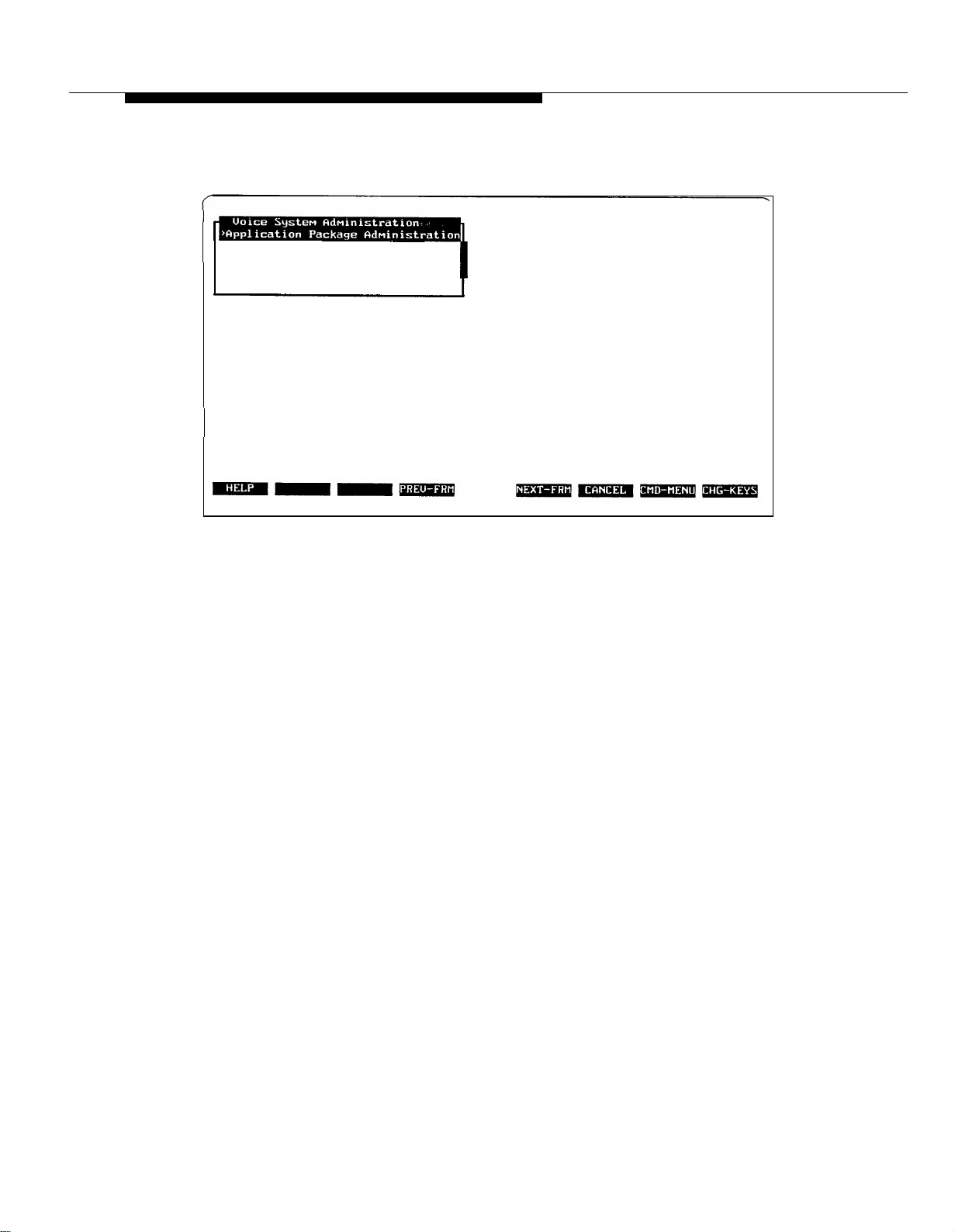
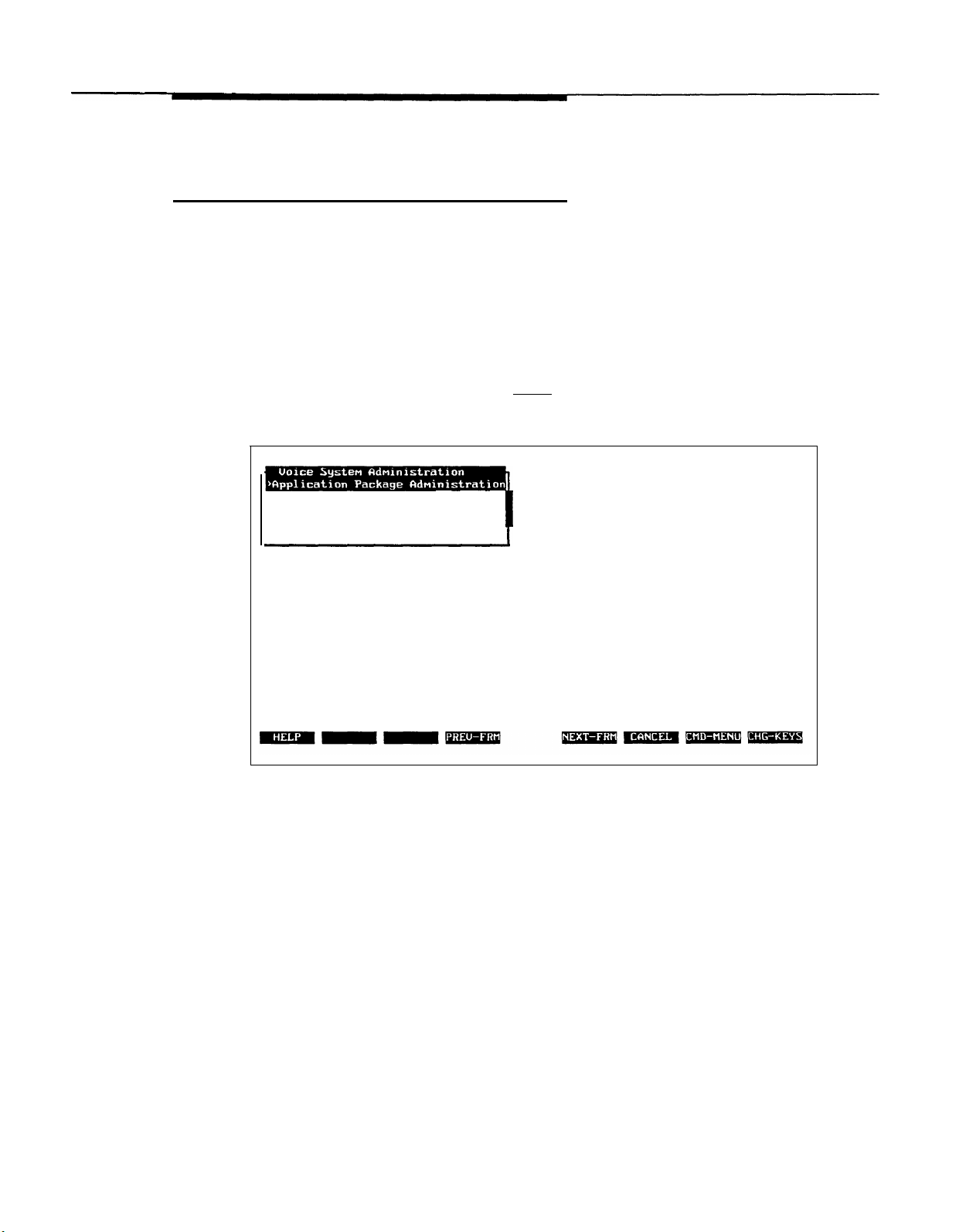
Move the Cursor to Application Package Administration and
3.
press (Enter).
— The Application Package Administration menu appears.
>Application Package Administration
Configuration Management
Reports
Switch Interfaces
System Monitor
AUDIX Voice Power
Select an application & press the Enter key.
4.
Move the cursor to Trunk Name Administration and
press(Enter).
— The Trunk Name Administration window displays the trunk names in
the order in which they were entered into AUDIX Voice Power. The
most recently added trunk name is always at the bottom of the list.
DID
WATS
Press ADD to add a trunk name, REMOVE to remove a trunk name, CANCEL to exit
direct dial line
WATS inbound line
3-18
Page 59

System
75 and DEFINITY G1 Initial Implementation
5. Administer the trunks.
Add a trunk name by using the following steps:
a.
Press [F3] (ADD).
— The Add a Trunk Name form appears.
>Trunk Name
DID
WATS
Trunk Name:
Description:
Enter trunk name
b.
Enter the trunk name and description.
Press [F3] (SAVE).
c.
— The Add a Trunk Name form closes and an Information window
appears.
Description
direct dial line
WATS inbound line
Press any key to continue. . .
d.
Press any key to continue.
3-19
Page 60

System 75 and DEFINlTY G1 Initial Implementation
Remove a trunk name by using the following steps:
Move
a.
b.
—
the cursor to the trunk name to be removed.
Press [F2] (REMOVE).
The Add a Trunk Name form closes and an Information window
appears.
>Trunk Name
DID
WATS
Press any key to continue. . .
c.
Press any key to continue.
Description
direct dial line
WATS inbound line
Handling Ambiguous Extensions
An ambiguous extension must not be used for the DCP or for any of the channels
assigned to AUDIX Voice Power. An ambiguous extension is one that starts with
a digit that could be part of a longer extension under the switch dial plan.
3-20
Handling Display Phones
On display phones, the message waiting lamp maybe shown as a call from the
extension assigned to channel 0. Attempting to return a call to this extension will
be blocked because of the Class of Restriction. If you have display phones, on
System 75/DEFINITY G1 assign the name “Get Voice Mail” to the extension
assigned to channel 0.
Page 61

Index
Documentation conventions, iii
Documents, related, v
A
Accessing, Configuration Management menu, 1-5
Adding trunk names, 3-19
Administration
analog channel, 3-8
call coverage, 3-14
hunt groups, 3-12
message waiting lamp parameters, 2-11
subscribers, 3-15
trunks, 3-17
Ambiguous extensions, 1-4, 3-20
Analog channel administration, 3-8
Assigning, class of restriction, 3-5
Assistance, obtaining, ii, 3-1
Audience, intended, ii
AUDIX Voice Power, checklist, 3-4
C
Call coverage paths, 3-14
Channel
assigning service, 1-5, 2-1
changing service, 2-6
changing state, 1-10
mapping extensions to, 1-14
Checklist, AUDIX Voice Power, 3-4
Class of restriction, assigning, 3-5
Code to Extinguish parameter, 2-11,2-12
Code to Light parameter, 2-11, 2-12
Configuration
hardware, 1-2
software, 1-3
Configuration Management menu, accessing, 1-5
Configuring, DCP extensions, 3-10
Connections, testing, 1-4
E
Extensions
ambiguous, 1-4, 3-20
DCP, 3-10
mapping to channels, 1-14
verifying, 1-13
F
Feature Access Code form, 2-12
FORM A - Channel Assignments, 1-4
FORM B - Switch Interface Administration, 2-7
FORM C - System Parameter Administration, 2-13
FORM D - Subscriber Administration, 3-15
Forms
Call Coverage, 3-15
Channel Assignments, 1-4
Class of Restriction, 3-6
DCP Link Display, 3-11
Display Station, 3-9
Feature Access Code, 2-12
Hunt Group, 3-13,3-14
Subscriber Administration, 3-15
Subscriber Station, 3-16
Switch Interface Administration, 2-7
System Parameter Administration, 2-13
Function keys, iii
H
Hardware configuration, 1-2
Hunt groups, administering, 3-12
D
DCP extensions, 3-10
Display phones, 3-20
I
Initial implementation, 2-1
Integrated mode, administering hunt groups, 3-12
Integrated system, 2-1
IN-1
Page 62

Index
K
Keys, iii
function, iii
Touch-Tone, iii
M
Mapping extensions to channels, 1-14
Message Waiting Lamp, 2-3
display phone, 3-20
parameters, 2-11
N
Non-integrated mode, administering hunt groups, 3-12
Non-integrated system, 2-2
0
S
Signaling Type parameter, 2-7
Software, versions, 3-1
Software configuration, 1-3
Subscriber administration, 3-15
Subscriber Administration form, 3-15
Switch interface parameters, 2-7
entering, 2-8
Switchhook Flash Duration parameter, 2-7
System Parameter Administration form, 2-13
System parameters, 2-11
entering, 2-13
T
Testing connections, 1-4
Touch-Tone keys, representation, iii
Trunk administration, 3-17
Trunk names
adding, 3-19
removing, 3-20
Obtaining assistance, ii, 3-1
P
Parameters
code to extinguish, 2-11, 2-12
code to light, 2-11, 2-12
message waiting lamp, 2-3, 2-11
refresh, 2-11
signaling type, 2-7
switch interface, 2-7
switchhook flash duration, 2-7
system, 2-11
wink disconnect interval, 2-7
R
Refresh parameter, 2-11
Removing trunk names, 3-20
U
Upgrade installation, 3-3
V
Verifying extensions, 1-13
W
Wink Disconnect Interval parameter, 2-7
IN-2
 Loading...