

Atrust T180L, T180LB User Manual

Atrust t180L / t180LB Thin Clients
User’s Manual
Internal Draft 0.04
Copyright © 2014-16 Atrust Computer Corp.

UM-t180L.LB-EN-16050510

Copyright and Trademark Statements
Copyright © 2014-16 Atrust Computer Corp. All rights reserved.
This document contains proprietary information that is protected by copyright. No part of this document may be
photocopied, reproduced, or translated to another language without the prior written consent of Atrust Computer
Corp.
Disclaimer
Atrust Computer Corp. (“Atrust”) makes no representations or warranties with respect to the contents or use of
this document, and specically disclaims any express or implied warranties of merchantability or tness for any
particular purpose. Atrust is not liable for technical or editorial errors or omissions contained herein. The information
in this document is subject to change without notice.
Trademark Statements
Atrust is a trademark of Atrust Computer Corp.
Microsoft, Windows, Windows Server, RemoteFX, and MultiPoint are trademarks or registered trademarks of the
Microsoft group of companies.
i
Citrix, ICA, XenApp, XenDesktop, and VDI-in-a-Box are trademarks of Citrix Systems, Inc. and/or one or more of its
subsidiaries, and may be registered in the United States Patent and Trademark Oce and in other countries.
VMware, VMware View, and VMware Horizon View are trademarks or registered trademarks of the VMware, Inc.
PCoIP is a registered trademark of Teradici Corporation in the United States and/or other countries.
Other product names mentioned herein are used for identication purposes only and may be trademarks and/or
registered trademarks of their respective companies.

ii
About This User’s Manual
This manual provides detailed instructions on how to set up, use, manage, and maintain Atrust t180L/t180LB
thin clients.
Manual Structure and Subjects
Chapter Subject
1 Provides an overview of Atrust t180L/t180LB thin clients.
2 Provides detailed instructions on how to set up Atrust t180L/t180LB thin clients.
3 Provides the basics of how to use Atrust t180L/t180LB thin clients.
4
Appendices
Specications Provides detailed information on key components of Atrust t180L/t180LB thin clients.
Provides instructions on how to congure client settings and customize Atrust t180L/t180LB
thin clients with the Atrust Client Setup console.
Provides supplementary instructions on advanced settings, maintenance, and upgrade for Atrust
t180L/t180LB thin clients.
Notes, Tips, and Warnings
Throughout this manual, the notes, tips, and warnings in the following formats are used to provide important
information, useful advice, and prevent injuries to you, damage to your devices, or loss of data on your system.
NOTE
• A note provides important information for a specic situation.
TIP
• A tip gives a piece of useful advice to perform a task more eciently.
WARNING
• A warning provides crucial information that must be followed to prevent injuries to
you, damage to your devices, or loss of data on your system.
Style Conventions
The following styles are used throughout this manual while referring to operational items on input devices,
hardware panels, or application interfaces.
Item Style Example
keys on the keyboard bold Ctrl + F2, Alt + F9, Alt + Tab
iii
application windows or
entry lists
buttons or tabs on a
window, toolbars, taskbar,
or menu
options on a window,
screen, list, or menu
selecting a series of options bold
rst letter
capitalized
bold OK, Next, Save, Applications tab
bold Add, Domain, Connection Type, High Quality
Conrm Dialog window, RDP Connection list, ICA Connection list,
View Connection list
Applications > Citrix ICA, Applications > Remote Desktop,
Applications > VMware View, Network > Wireless,
Devices > Printer, System > Time Zone

iv
Safety and Regulatory Information
Regulatory Statement
Federal Communications Commission Interference Statement
This equipment has been tested and found to comply with the limits for a Class B digital device, pursuant to Part
15 of the FCC Rules. These limits are designed to provide reasonable protection against harmful interference in a
residential installation. This equipment generates, uses and can radiate radio frequency energy and, if not installed
and used in accordance with the instructions, may cause harmful interference to radio communications. However,
there is no guarantee that interference will not occur in a particular installation. If this equipment does cause
harmful interference to radio or television reception, which can be determined by turning the equipment o and
on, the user is encouraged to try to correct the interference by one of the following measures:
• Reorient or relocate the receiving antenna.
• Increase the separation between the equipment and receiver.
• Connect the equipment into an outlet on a circuit dierent from that to which the receiver is connected.
• Consult the dealer or an experienced radio/TV technician for help.
FCC Caution: Any changes or modications not expressly approved by the party responsible for compliance could
void the user’s authority to operate this equipment. This device complies with Part 15 of the FCC Rules. Operation is
subject to the following two conditions: (1) This device may not cause harmful interference, and (2) this device must
accept any interference received, including interference that may cause undesired operation.
IMPORTANT NOTE:
FCC Radiation Exposure Statement
This equipment complies with FCC radiation exposure limits set forth for an uncontrolled environment. This
equipment should be installed and operated with minimum distance 20 cm between the radiator & your body.
This transmitter must not be co-located or operating in conjunction with any other antenna or transmitter.
Regulatory Information
WEEE (Waste Electrical and Electronic Equipment) Directive
In the European Union, this symbol indicates that this product should not be disposed of with
household waste. It should be deposited at an appropriate facility to enable recovery and recycling. For
Safety Information
proper disposal, please contact your local recycling or hazardous waste center.
WARNING
• Use only power supplies listed in the user instructions.
WARNING
• Risk of explosion if battery is replaced by an incorrect type. Dispose of used
batteries according to the instructions.
v
WARNING
• For safety, do not make mechanical or electrical modications to the equipment.
• Do not remove equipment covers and access any of the components inside the
equipment. Any access inside the equipment without an authorized or certied
technician may cause serious injuries and damage. For any problem, contact your
dealer for assistance.
• You should only make repairs as authorized by the product documentation.
Repairs, replacement, expansion, and upgrades not performed by a certied service
technician may cause injuries to you, damage your system, and void your warranty.

vi

Table of Contents
Copyright and Trademark Statements i
Disclaimer i
Trademark Statements i
About This User’s Manual ii
Manual Structure and Subjects ii
Notes, Tips, and Warnings ii
Style Conventions iii
Safety and Regulatory Information iv
Regulatory Statement iv
Regulatory Information v
Safety Information v
1 Overview 1
1.1 Introduction 3
1.2 Features 3
vii
1.3 Package Contents 4
1.4 Exterior Views 5
1.5 Panel Components 6
1.6 LED Indicators 8
2 Setting Up Your t180L / t180LB 9
2.1 Positioning Your t180L / t180LB 11
2.2 Assembling the AC Adapter 16
2.3 Getting Connected 16
3 Getting Started 17
3.1 Learning the Basics 19
4 Conguring Client Settings 37
4.1 Atrust Client Setup 39
4.1.1 Interface Overview 39
4.1.2 Client Settings at a Glance 40
4.2 Conguring System Settings 41
4.2.1 System Tab Overview 41
4.2.2 Available Settings at a Glance 42
4.2.3 Conguring Time Zone and Time Server 43
4.2.4 Conguring the Access Privileges and Passwords of Atrust Client Setup 44
4.2.5 Conguring Shadow Settings for Remote Assistance 46
4.2.6 Updating Firmware from the Management Computer 48
4.2.7 Enabling or Disabling the Appliance Mode 50
4.2.8 Enabling or Disabling Auto Setup 54
4.2.9 Conguring the Quick Connection Mode 54
4.2.10 Conguring Advanced Quick Connection Settings 56
4.2.11 Enabling or Disabling the Command-line Functions 60
4.2.12 Collecting Event Logs and Capturing Related Screens 61
4.2.13 Uploading Files for Error Reporting 63
4.2.14 Importing Certicates for Remote Computers 64
4.2.15 Enabling or Disabling Auto Registration 68

viii
4.3 Conguring User Interface Settings 69
4.3.1 User Interface Tab Overview 69
4.3.2 Available Settings at a Glance 70
4.3.3 Conguring Display Settings 70
4.3.4 Customizing Desktop and System Language Settings 73
4.3.5 Hiding or Showing Quick Access Shortcuts 75
4.3.6 Using a Custom Wallpaper 76
4.3.7 Adjusting Keyboard Settings 77
4.3.8 Conguring Mouse Settings 79
4.3.9 Conguring Screensaver Settings 80
4.4 Conguring External Device Settings 81
4.4.1 Devices Tab Overview 81
4.4.2 Available Settings at a Glance 82
4.4.3 Conguring Settings for USB Storage Devices 82
4.4.4 Manually Mount and Eject Attached USB Storage Devices 83
4.4.5 Disabling or Enabling Attached Audio Devices 84
4.4.6 Using USB Audio Devices 85
4.4.7 Adding a Local Printer 86
4.4.8 Adding a Network Printer 89
4.5 Conguring Network Settings 90
4.5.1 Network Tab Overview 90
4.5.2 Available Settings at a Glance 91
4.5.3 Conguring Wired Network Settings 92
4.5.4 Enabling or Disabling Wake On LAN 95
4.5.5 Establishing and Stopping a VPN connection 96
4.5.6 Conguring Virtual Private Network Settings 100
4.5.7 Creating the Mapping of IP Addresses to Names of Hosts 101
4.5.8 Conguring the Failover Cluster List 103
4.5.9 Changing the Host Name of Your Thin Client 105
4.5.10 Enabling or Disabling the Wireless Interface 106
4.5.11 Conguring the Trigger Threshold for Roaming 107
4.5.12 Establishing and Stopping a Wireless Connection 108
4.5.13 Conguring Wireless Connection Settings 111
4.5.14 Conguring Proxy Settings for Web-based Access to Services 112
4.6 Conguring Service Access Settings 114
4.6.1 Applications Tab Overview 114
4.6.2 Available Settings at a Glance 115
4.6.3 Conguring Basic RDP Connection Settings 116
4.6.4 Accessing Remote Desktop Services 125
4.6.5 Conguring Advanced RDP Connection Settings 131
4.6.6 Conguring Basic ICA Connection Settings 146
4.6.7 Switching the Citrix Receiver Version 159
4.6.8 Enabling or Disabling Esc to Quit on the Web Logon Screen 160
4.6.9 Conguring Keyboard Layout and Type for Citrix ICA Sessions 161
4.6.10 Accessing Citrix Services 162
4.6.11 Conguring Advanced ICA Connection Settings 169
4.6.12 Conguring Basic VMware View Connection Settings 198
4.6.13 Accessing VMware View or Horizon View Services 200
4.6.14 Conguring Advanced View Connection Settings 202
4.6.15 Conguring SSH Connection Settings 207
4.6.16 Launching SSH and Telnet Sessions 209
Appendices 211
A.1 Resetting Your t180L/t180LB to the Factory Default 213
A.2 Updating Firmware for Your t180L/t180LB 214
A.3 Using SECUREMATRIX Authentication for VMware Connections 216
Specications 223

Overview
1
This chapter provides an overview of your t180L / t180LB thin clients.
1.1 Introduction
Desktop virtualization and simple endpoint devices 3
1.2 Features
Key features of Atrust t180L / t180LB 3
1.3 Package Contents
Check your package contents 4
1.4 Exterior Views
Overview of thin client outside elements 5
1.5 Panel Components
Descriptions of front and rear panel components 6
1.6 LED Indicators
Descriptions of signals for LED indicators 8


Overview
Introduction
1.1 Introduction
Desktop virtualization provides a new perspective to reconsider the design and implementation of an IT
infrastructure. In a desktop virtualization infrastructure, a station is no longer a cumbersome desktop, but simply an
endpoint device for users to access delivery services from the server(s).
With the introduction of the desktop virtualization technologies, you can considerably benet from:
• On-demand access to applications / desktops
• Centralized management of work environments
• Drastically reduced endpoint software / hardware issues
• Simplied system maintenance
• Improved system security
• More scalability with low-cost endpoint devices
1.2 Features
3
The key features of Atrust t180L / t180LB thin clients are:
• Support for dual displays (DVI-I and DVI-D)
• Support for a wide range of desktop virtualization solutions from industry-leading companies:
Microsoft® Remote Desktop
Citrix® XenApp™, XenDesktop®, and VDI-in-a-Box™
VMware® View™ and VMware® Horizon View™
• Support for high-denition technologies:
Microsoft® RemoteFX®
Citrix® HDX™
VMware® View™ PCoIP®
• Simple click-access to various applications / desktops
• Built-in Atrust Client Setup as the local client management console
Overview
4
Package Contents
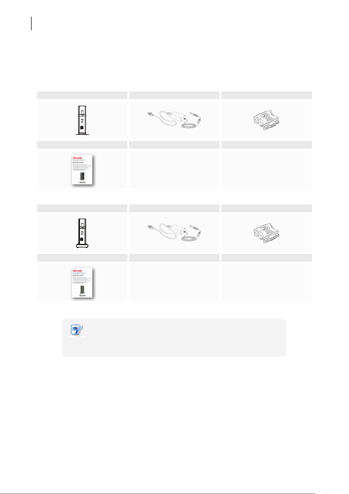
1.3 Package Contents
Please check your package contents. Ensure that all of the items are present in your package. If any items are
missing or damaged, please contact your dealer immediately.
Atrust t180L AC Adapter DVI-I to VGA Adapter
Quick Start Guide
Atrust t180LB AC Adapter DVI-I to VGA Adapter
Quick Start Guide
NOTE
• Your package may not contain a hard copy of the Quick Start Guide. In this
case, a soft copy in PDF format will be provided.
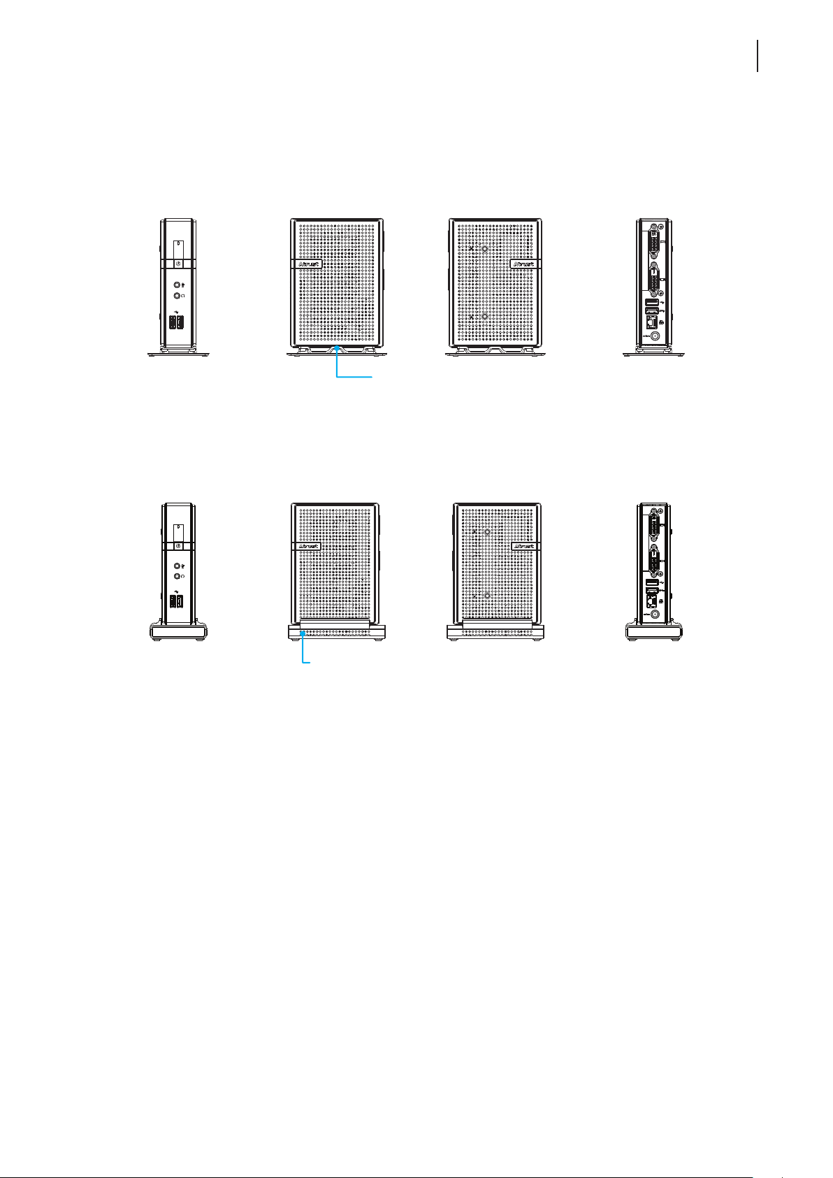
1.4 Exterior Views
Front Right Side Left Side Rear
Standard Stand
Overview
Exterior Views
5
Front Right Side Left Side Rear
Selectable Stand with Wireless Module
Overview
6
Panel Components
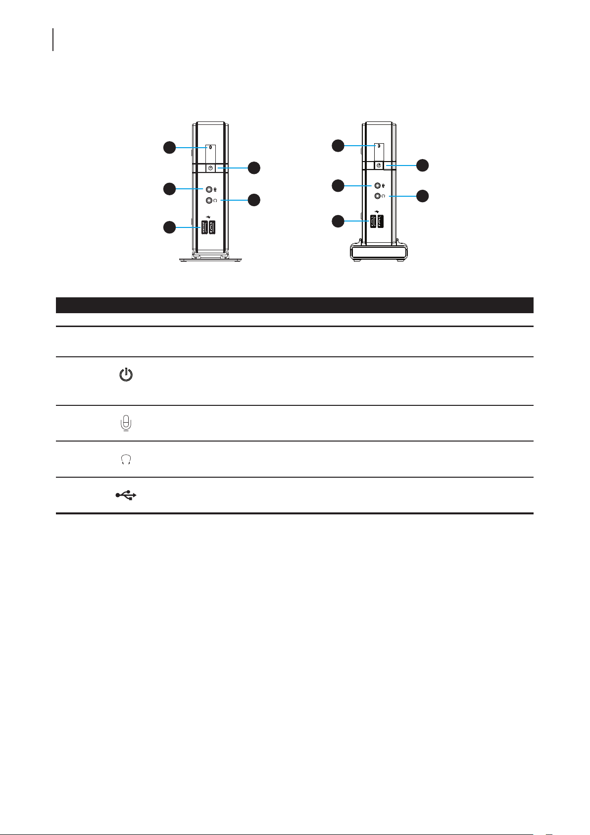
1.5 Panel Components
1
1
2
3
3
4
5
Front Panel Components
No. Sign Name Description
1 Power LED Indicates the status of power.
• Press to turn on the thin client.
2
3
Power button
Microphone port Connects to a microphone.
• Press to exit the System Sleep mode.
See page 20 for Suspend feature.
• Long press to power off the thin client.
5
2
4
4
5
Headphone port Connects to a set of headphones or a speaker system.
USB port
(USB 2.0)
Connects to a USB device.
Overview
Panel Components
7
6
6
7
8
9
10
11
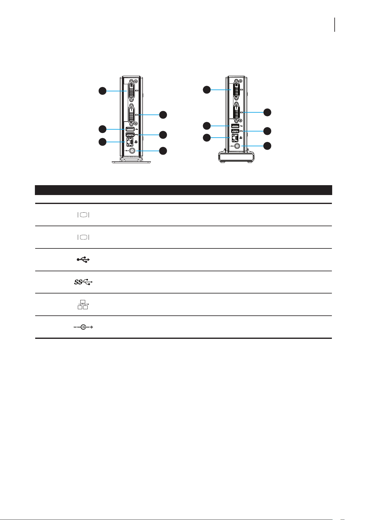
Rear Panel Components
No. Sign Component Name Description
6
7
8
DVI-I port Connects to a monitor.
DVI-D port Connects to a monitor.
USB port
(USB 2.0)
Connects to a USB device.
8
10
7
9
11
10
11
9
USB port
(USB 3.0)
LAN port Connects to a network.
DC IN Connects to an AC adapter.
Connects to a USB device.
Overview
8
LED Indicators
1.6 LED Indicators
Your t180L / t180LB is equipped with a Power LED to indicate the state of power. The meanings of LED signals
are described as follows:
LED Signal Meaning
Off The client is off.
Power LED
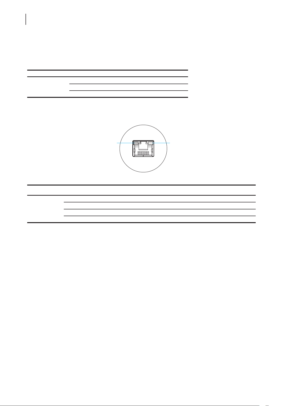
The LAN port of your t180L / t180LB has two LED indicators showing the state of networking. The meanings of
LED signals are described as follows:
Orange The client is in System Sleep mode.
Blue The client is on.
SPEED LED LINK/ACT LED
LED Signal
SPEED LED
(transmission rate)
Off Off The client is not connected to a LAN.
Off Amber blinking The client connects to a 10 Mbps LAN.
Orange Amber blinking The client connects to a 100 Mbps LAN.
Green Amber blinking The client connects to a 1000 Mbps LAN.
LINK/ACT LED
(linking/transmission activity)
Meaning

Setting Up Your t180L / t180LB
This chapter provides detailed instructions on how to set up your
t180L / t180LB thin clients.
2.1 Positioning Your t180L / t180LB
To mount your t180L
Step 1: Remove the Stand from Your t180L
Step 2: Understand Your Stand / VESA Mount Kit for t180L
Step 3: Store Screws inside the Bracket
Step 4: Remove Screws from the Bracket
Step 5: Mount Your t180L
Mounting with Another VESA Bracket (t180LB)
2.2 Assembling the AC Adapter
How to assemble the AC adapter and its detached plug 16
2
11
12
13
13
14
15
2.3 Getting Connected
How to connect peripherals and power for t180L / t180LB 16

Setting Up Your t180L / t180LB
2.1 Positioning Your t180L / t180LB
There are two ways to position your t180L:
• Put it (with its stand) on a desk or a desired place uprightly.
• Mount it on the back of a monitor using a VESA mount kit.
To mount your t180L on the back of a monitor, please follow the steps below:
Step 1: Remove the Stand from Your t180L
Step 2: Understand Your Stand / VESA Mount Kit for t180L
Step 3: Store Away Screws inside the Bracket
Step 4: Remove Screws from the Bracket
Step 5: Mount Your t180L
11
Positioning Your t180L / t180LB
NOTE
• If your t180 uses a non-standard stand with the wireless module, you will need a
dierent VESA bracket to mount it on the back of the monitor. For details, please
refer to topic “Mounting with Another VESA Bracket (t180LB)” on page 15.
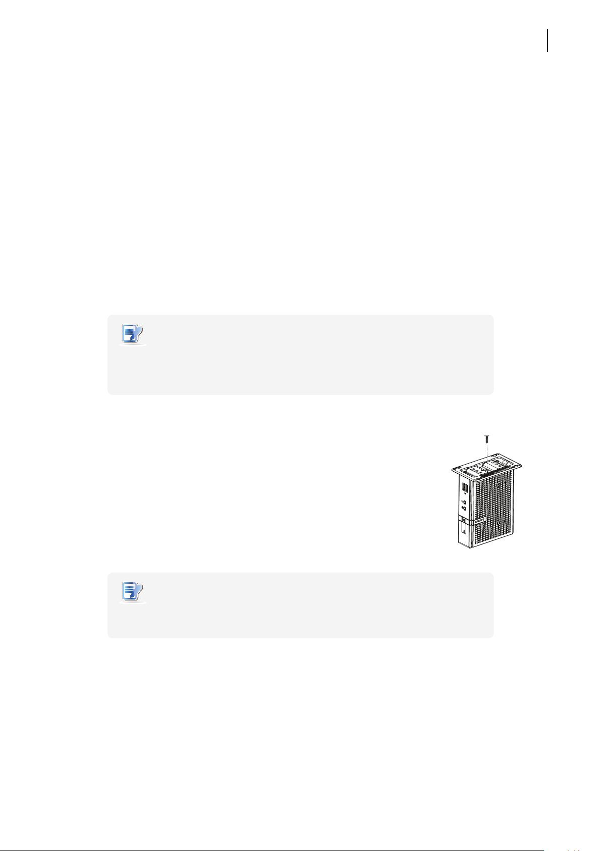
Step 1: Remove the Stand from Your t180L
To remove the stand from your t180L, please do the following:
1. Place your t180L on a at surface with the stand side upward.
2. Remove the screw that xes the stand to your t180L.
3. Store away the removed screw inside the stand. Detailed instructions will be
provided in Step 2 and 3.
NOTE
• It’s highly recommended to store screws away inside the stand when not needed
to prevent them getting lost.
Manufacturer
Model Name
Model / 型號 / 型号 : Atrust t62
Input/輸入 / 输入
台灣製造 / 台湾制造 / Made in Taiwan
冠信电脑股份有限公司
:
精致型电脑
:
JPAA
製造商:冠信電腦股份有限公司 制造商
精簡型電腦 产品名称
:
Atrust Computer Corp.
:
Thin Client 產品名稱
:
+5V 3A
:
Setting Up Your t180L / t180LB
12
Positioning Your t180L / t180LB
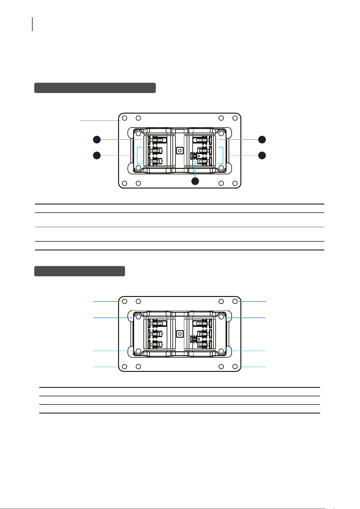
Step 2: Understand Your Stand / VESA Mount Kit for t180L
The stand for your t180L is dual-purpose: it can be used as a stand or as a VESA mount kit. All screws of dierent
types supplied with the stand / VESA mount kit can be stored away inside the main bracket when not needed.
Screws Stored Away inside the Bracket
The following gure shows dierent types of screws stored away inside the main bracket.
Dual-purpose
bracket
1
2
3
Screw Type Number Description
1 2
2 4
3 1 The smallest-size screw used to secure the bracket to your t180L as a stand.
The largest-size screws used to secure the bracket to a monitor as a VESA mount if the
middle-size screws cannot rmly secure the bracket and your t180L to the monitor.
The middle-size screws used to secure the bracket to your t180L and to a monitor
when using the bracket as a VESA mount.
Mount Holes on the Bracket
Refer to the following gure and descriptions for the VESA mount holes on the bracket.
1
1
2
1
2
2
1
Mount Hole Description
1 The VESA mount holes used to secure the bracket to a monitor (only two of them will be used).
2 The VESA mount holes used to secure the bracket to your t180L (only two of them will be used).
2
2
1
Setting Up Your t180L / t180LB
Positioning Your t180L / t180LB
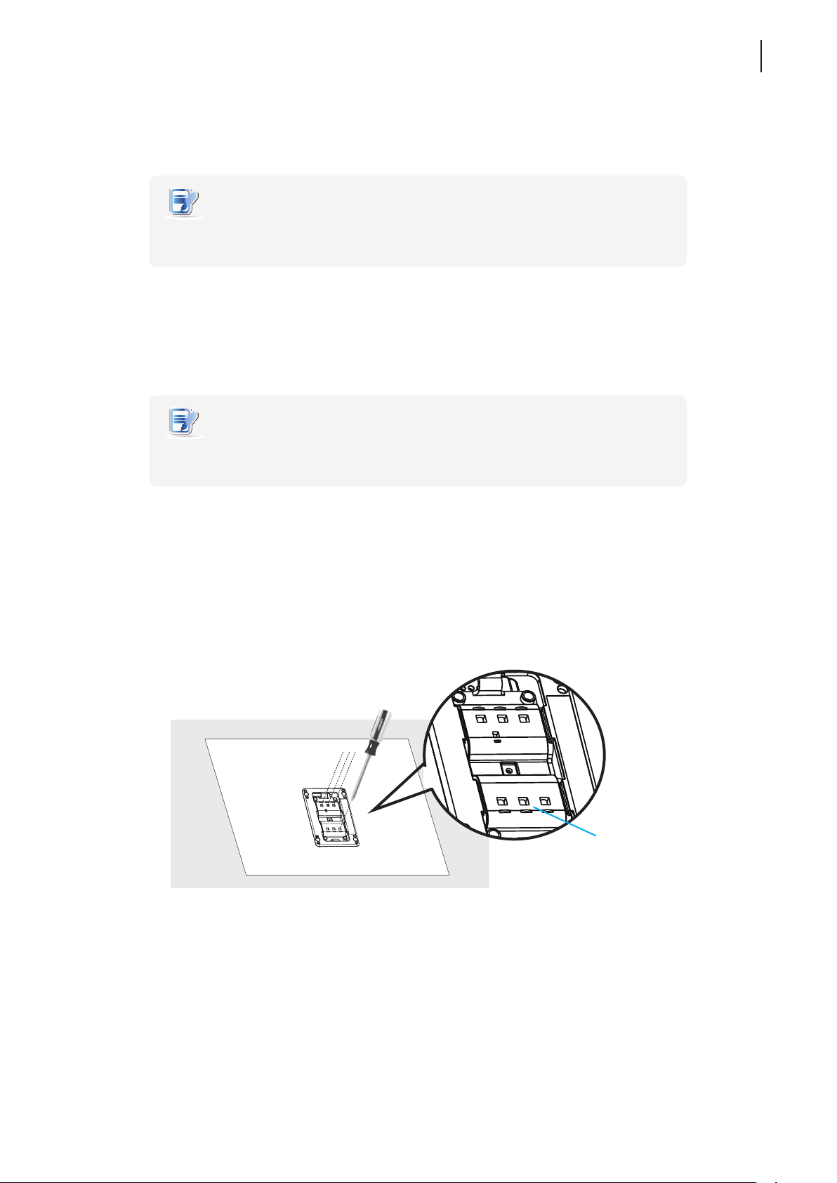
Step 3: Store Screws inside the Bracket
To store screws inside the bracket, please do the following:
NOTE
• It’s highly recommended to store screws inside the bracket when not needed
to prevent them getting lost.
1. Place a sheet of paper or a piece of cloth on a at surface, and then put your bracket on that paper or cloth
with the screw storage side upward.
2. Place the screw upon its storage space, and push the screw into the space with your nger until it clicks
into place. For the smallest-size screw, use the tip of a screwdriver instead to push the screw.
NOTE
• Please refer to the gure and descriptions in “Step 2: Understand Your Stand / VESA
Mount Kit for t180L” for the correct storage space of each screw.
13
Step 4: Remove Screws from the Bracket
To remove screws stored inside the bracket, please do the following:
1. Place a sheet of paper or a piece of cloth on a at surface, and then put your bracket on that paper or cloth
with the screw storage side downward.
2. Insert the tip of a screwdriver into the square holes to remove the desired screws from the bracket.
Square Hole
Setting Up Your t180L / t180LB
2
1
2
2
14
Positioning Your t180L / t180LB
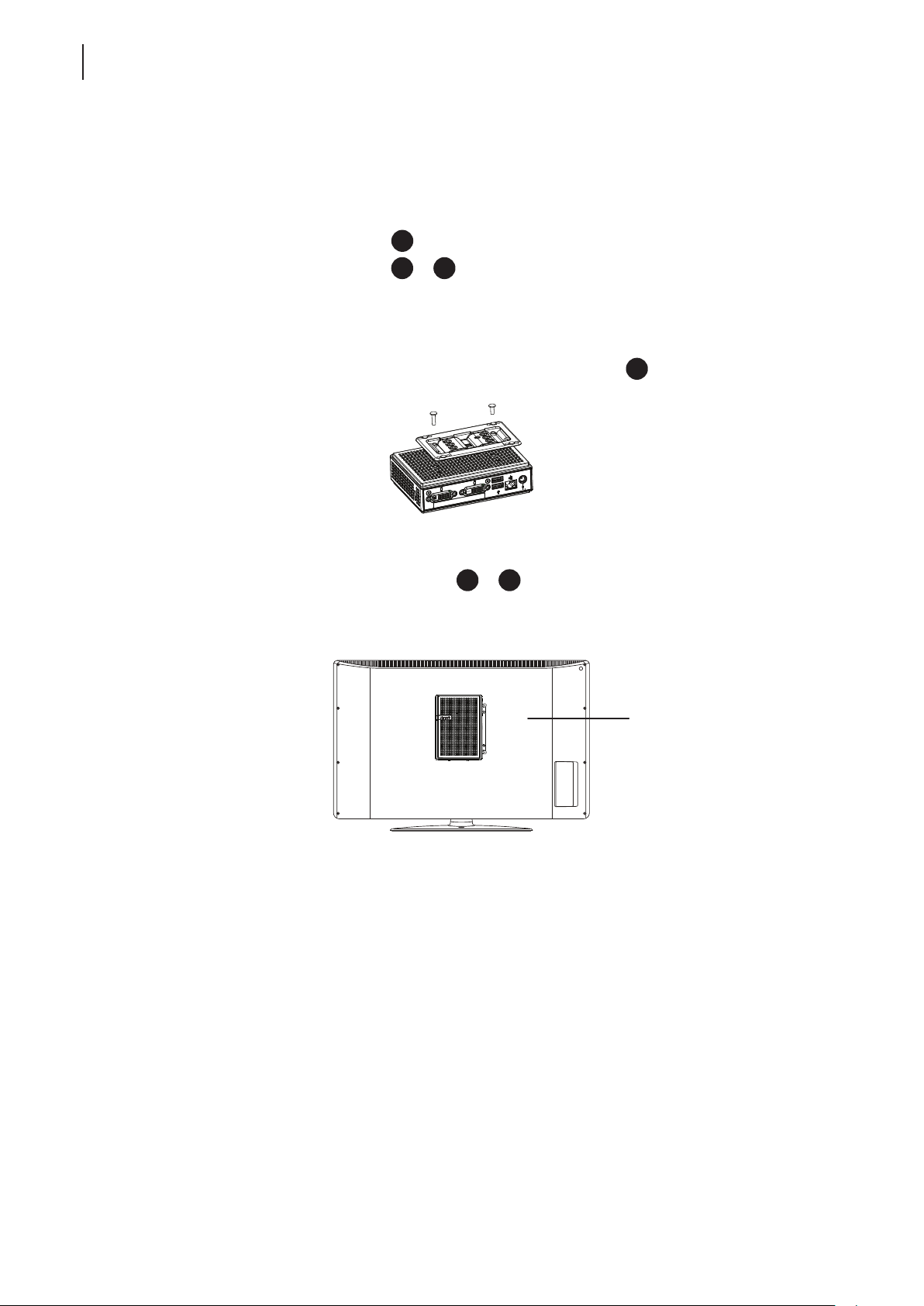
Step 5: Mount Your t180L
To mount your t180L on the back of a monitor, please do the following:
1. Refer to Step 2 and Step 4 to prepare required screws for mounting your t180L.
• You will need two (2) screws of type
• You will need two (2) screws of type
2. Place your t180L on a at surface with the VESA mount hole side upward.
3. Refer to Step 2 to choose two of the four VESA mount holes on the bracket to align with two mount holes
on your t180L such that the bracket projects out and is closer to the rear panel than the front one as shown
below, and then secure the bracket to your t180L with two (2) screws of type
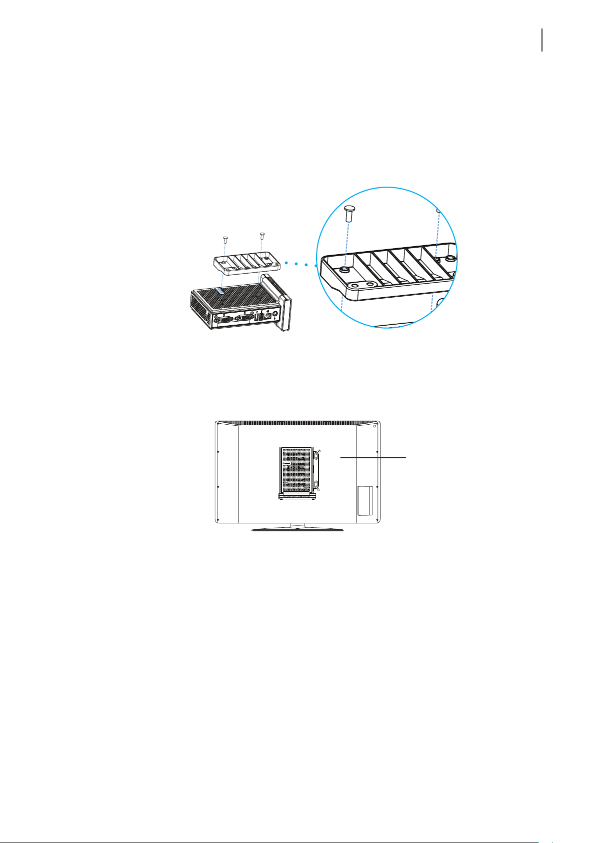
4. Align the mount holes on the bracket with the mount holes on the back of the monitor, and then secure the
bracket to the monitor with two (2) screws of type
of the monitor and the rear panel of your t180L is facing rightward as shown below.
to secure the bracket to your t180L.
or 2 to secure the bracket to the monitor.
.
or 1. Ensure that your t180L is located in the center
Have t180L’s rear panel
facing rightward.
Setting Up Your t180L / t180LB
Positioning Your t180L / t180LB
Mounting with Another VESA Bracket (t180LB)
In case that your t180 uses a non-standard stand with the wireless module (t180LB), a dierent VESA bracket will be
provided for you to mount your t180LB on the back of a monitor.
To mount your t180LB, follow the steps below:
1. Align two mount holes on the VESA bracket with two mount holes on your t180LB, and then secure the
bracket to your t180LB with two (2) screws as shown below.
15
2. Align the mount holes on the VESA bracket with the mount holes on the monitor, and then secure the
bracket and t180LB to the monitor with two (2) screws as shown. Ensure that your t180LB is located in the
center of the monitor and the rear panel of your t180LB is facing rightward as shown below.
Have t180LB’s rear panel
facing rightward.
Setting Up Your t180L / t180LB
16
Assembling the AC Adapter
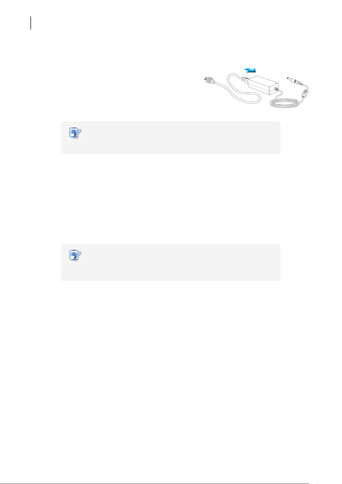
2.2 Assembling the AC Adapter
To assemble the AC adapter for your t180L / t180LB, please do the following:
1. Unpack your thin client package and take out the AC adapter
and its detached AC power cord.
2. Press the female end of the power cord into the male connector
of the AC adapter.
NOTE
• The plug of the supplied power cord may vary with your area.
2.3 Getting Connected
To make connections for your t180L / t180LB, please do the following:
1. Connect your t180L / t180LB to your local network with an Ethernet cable.
2. Connect a keyboard and mouse to your t180L / t180LB with USB ports.
3. Connect and turn on the monitor(s).
4. Connect your t180L / t180LB to a power outlet using the AC adapter included in the package.
NOTE
• For detailed instructions on how to assemble the supplied AC adapter, please refer
to section “2.2 Assembling the AC Adapter” on page 16.
5. Connect other peripherals for your t180L / t180LB if needed.

Getting Started
3
This chapter provides the basics of how to use your t180L/t180LB.
3.1 Learning the Basics
Topic 1: Powering On Your t180L/t180LB
Topic 2: Conguring the Time Zone
Topic 3: Returning to the Quick Connection Screen
Topic 4: Accessing Desktops or Applications
20
21
22
23

3.1 Learning the Basics
The following topics will guide you through the basics of using your t180L/t180LB:
Topic 1: Powering On Your t180L/t180LB
Topic 2: Conguring the Time Zone
Topic 3: Returning to the Quick Connection Screen (if needed)
Topic 4: Accessing Desktops or Applications
• Microsoft Remote Desktop Services (RDP sessions)
• Citrix Services (ICA sessions)
• VMware View or Horizon View Services (View sessions)
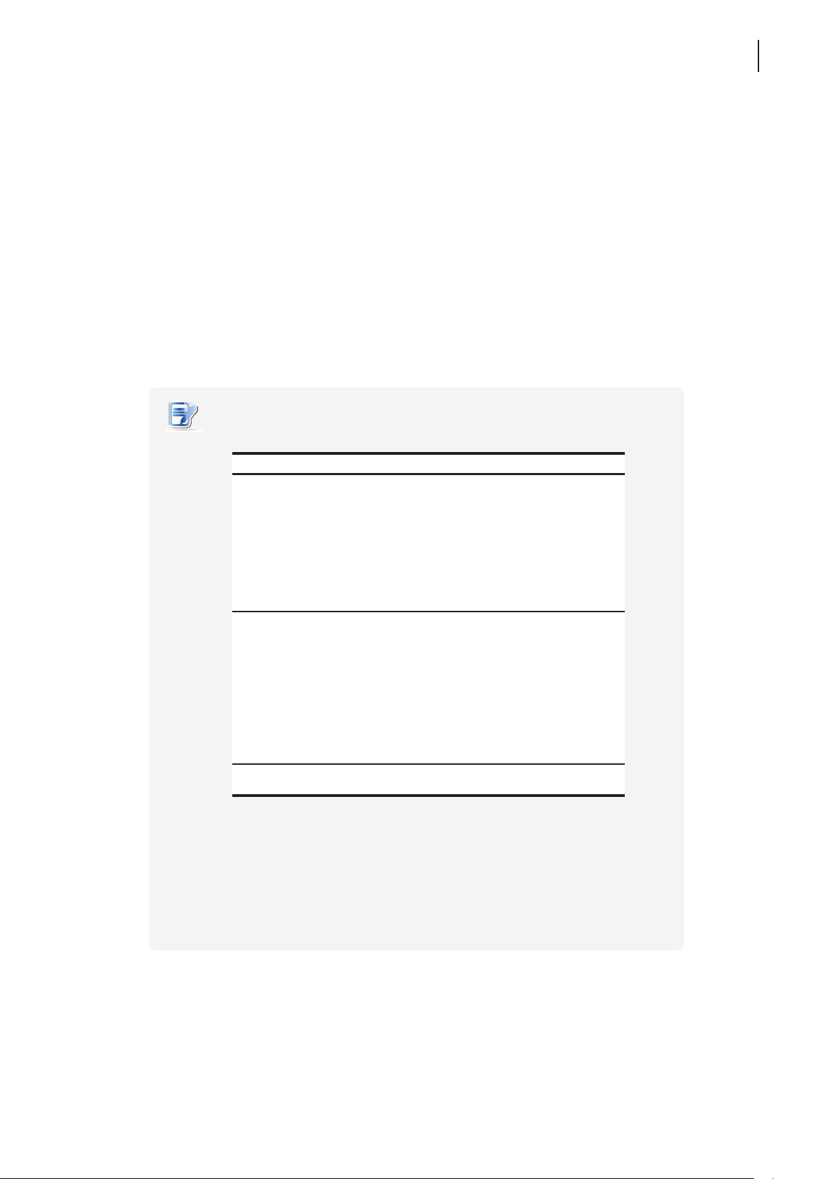
NOTE
• Three client modes are available for your t180L/t180LB:
Getting Started
Learning the Basics
19
No. Mode Description
The client will start up directly with the desired
RDP / ICA / View session and perform the
congured action after exiting the session.
1 Appliance
2 Autostart
3 Quick Connection
Available actions include:
• Re-launching a new session
• Restarting the thin client
• Turning off the thin client
The client will start up directly with the desired
RDP / ICA / View session and perform the
congured action after exiting the session.
Available actions include:
• Returning to the local desktop
• Re-launching a new session
• Restarting the thin client
• Turning off the thin client
The default. The client will enter Atrust Quick
Connection screen after system startup.
• In Quick Connection mode, you can access Microsoft Remote Desktop / Citrix /
VMware View or Horizon View services quickly without much client conguration
required. The main purpose of this chapter is to guide you through the use of your
t180L/t180LB under the Quick Connection mode.
• To understand other modes, congure advanced settings, and customize your
t180L/t180LB, please refer to chapter 4 “Conguring Client Settings” on page 37.
Getting Started
20
Learning the Basics
Topic 1: Powering On Your t180L/t180LB
To start using your t180L/t180LB, please do the following:
1. Ensure that your monitor is connected and turned on.
NOTE
• Please note that you need to connect and turn on your monitor before powering
up the thin client. Otherwise, the client may fail to set an appropriate resolution
for the connected monitor.
2. Press the Power button to turn on the client. Wait a moment for Atrust Quick Connection screen to appear.
3. (a) Go to Topic 2 to set the time zone for the rst time use.
(b) Go to Topic 4 if the time zone had been set.
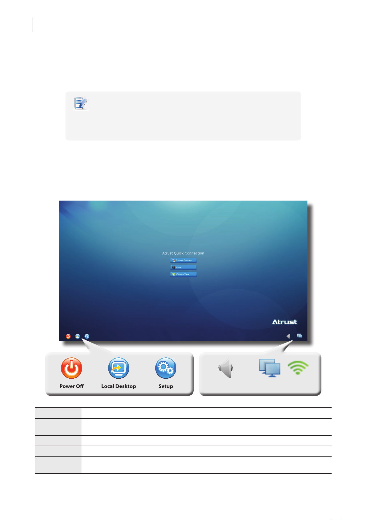
Atrust Quick Connection Screen
Power Off Click the icon to suspend, shut down, or restart the system.
Local Desktop
Setup Click the icon to launch Atrust Client Setup.
Mixer Click the icon to congure audio settings.
Network
Click the icon to enter the local Linux desktop.
To return to this screen from the local Linux desktop, see Topic 3.
Indicates the network type (wired or wireless) and status.
Click the icon to congure network settings.
NetworkMixer
 Loading...