


Atrust t60 / t62 Thin Clients
USER’S MANUAL
Version 1.06
Copyright © 2012-14 Atrust Computer Corp.
UM-t60.t62-EN-14071611

i
Copyright and Trademark Statements
Copyright © 2012-14 Atrust Computer Corp. All rights reserved.
This document contains proprietary information that is protected by copyright. No part of this document may be photocopied, reproduced, or translated to another language without the prior written consent of Atrust Computer Corp.
Disclaimer
Atrust Computer Corp. (“Atrust”) makes no representations or warranties with respect to the contents or use of this document, and specifically disclaims any express or implied warranties of merchantability or fitness for any
particular purpose. Atrust is not liable for technical or editorial errors or omissions contained herein. The information in this document is subject to change without notice.
Trademark Statements
Atrust is a trademark of Atrust Computer Corp.
Microsoft, Windows, Windows Server, RemoteFX, and MultiPoint are trademarks or registered trademarks of the Microsoft group of companies.
Citrix, ICA, XenApp, XenDesktop, and VDI-in-a-Box are trademarks of Citrix Systems, Inc. and/or one or more of its subsidiaries, and may be registered in the United States Patent and Trademark Office and in other countries.
VMware, VMware View, and VMware Horizon View are trademarks or registered trademarks of the VMware, Inc.
PCoIP is a registered trademark of Teradici Corporation in the United States and/or other countries.
Other product names mentioned herein are used for identification purposes only and may be trademarks and/or registered trademarks of their respective companies.
ii
About This User’s Manual
This manual provides detailed instructions on how to set up, use, manage, and maintain Atrust t60/t62 thin clients.
Manual Structure and Subjects
Chapter |
Subject |
|
|
1Provides an overview of Atrust t60/t62 thin clients.
2Provides detailed instructions on how to set up Atrust t60/t62 thin clients.
3Provides the basics of how to use Atrust t60/t62 thin clients.
4Provides instructions on how to configure client settings and customize Atrust t60/t62 thin clients with the Atrust Client Setup console.
Appendices |
Provides supplementary instructions on the maintenance and upgrade of |
|
Atrust t60/t62 thin clients. |
||
|
||
|
|
|
Specifications |
Provides detailed information on key components of Atrust t60/t62 thin clients. |
Notes, Tips, and Warnings
Throughout this manual, the notes, tips, and warnings in the following formats are used to provide important information, useful advice, and prevent injuries to you, damage to your devices, or loss of data on your system.
NOTE
• A note provides important information for a specific situation.
TIP
• A tip gives a piece of useful advice to perform a task more efficiently.
WARNING
• A warning provides crucial information that must be followed to prevent injuries to you, damage to your devices, or loss of data on your system.

iii
Style Conventions
The following styles are used throughout this manual while referring to operational items on input devices, hardware panels, or application interfaces.
Item |
Style |
Example |
|
|
|
|
|
keys on the keyboard |
bold |
Ctrl + F2, Alt + F9, Alt + Tab |
|
|
|
|
|
application windows or |
first letter |
Confirm Dialog window, RDP Connection list, ICA Connection list, |
|
entry lists |
capitalized |
View Connection list |
|
|
|
|
|
buttons or tabs on a |
|
|
|
window, toolbars, taskbar, |
bold |
OK, Next, Save, Applications tab |
|
or menu |
|
|
|
|
|
|
|
options on a window, |
bold |
Add, Domain, Connection Type, High Quality |
|
screen, list, or menu |
|||
|
|
||
|
|
|
|
|
|
Applications > Citrix ICA, Applications > Remote Desktop, |
|
selecting a series of options |
bold |
Applications > VMware View, Network > Wireless, |
|
|
|
Devices > Printer, System > Time Zone |
|
|
|
|

iv
Safety and Regulatory Information
Regulatory Statement
Federal Communications Commission Interference Statement
This equipment has been tested and found to comply with the limits for a Class B digital device, pursuant to Part 15 of the FCC Rules. These limits are designed to provide reasonable protection against harmful interference in a residential installation. This equipment generates, uses and can radiate radio frequency energy and, if not installed and used in accordance with the instructions, may cause harmful interference to radio communications. However, there is no guarantee that interference will not occur in a particular installation. If this equipment does cause harmful interference to radio or television reception, which can be determined by turning the equipment off and on, the user is encouraged to try to correct the interference by one of the following measures:
•Reorient or relocate the receiving antenna.
•Increase the separation between the equipment and receiver.
•Connect the equipment into an outlet on a circuit different from that to which the receiver is connected.
•Consult the dealer or an experienced radio/TV technician for help.
FCC Caution: Any changes or modifications not expressly approved by the party responsible for compliance could void the user’s authority to operate this equipment. This device complies with Part 15 of the FCC Rules. Operation is subject to the following two conditions: (1) This device may not cause harmful interference, and (2) this device must accept any interference received, including interference that may cause undesired operation.
IMPORTANT NOTE:
FCC Radiation Exposure Statement
This equipment complies with FCC radiation exposure limits set forth for an uncontrolled environment. This equipment should be installed and operated with minimum distance 20 cm between the radiator & your body.
This transmitter must not be co-located or operating in conjunction with any other antenna or transmitter.
v
Regulatory Information
WEEE (Waste Electrical and Electronic Equipment) Directive
In the European Union, this symbol indicates that this product should not be disposed of with household waste. It should be deposited at an appropriate facility to enable recovery and recycling. For proper disposal, please contact your local recycling or hazardous waste center.
Safety Information
WARNING
• Use only power supplies listed in the user instructions.
WARNING
• Don’t use a keyboard and mouse that in total require more than 200 mA of rated current during operation.
WARNING
• For safety, do not make mechanical or electrical modifications to the equipment.
•Do not remove equipment covers and access any of the components inside the equipment. Any access inside the equipment without an authorized or certified technician may cause serious injuries and damage. For any problem, contact your dealer for assistance.
•You should only make repairs as authorized by the product documentation. Repairs, replacement, expansion, and upgrades not performed by a certified service technician may cause injuries to you, damage your system, and void your warranty.

vi
Certification Information
Atrust t60/t62 thin clients that earn the ENERGY STAR prevent greenhouse gas emissions by meeting strict energy efficiency guidelines set by the U.S. Environmental Protection Agency and the U.S. Department of Energy.
NOTE
• Display Sleep Mode. Within 10 minutes of user inactivity, the display will enter the Display Sleep mode with a blank screen and reduced power consumption by the factory default settings. The display returns to the Display Normal mode upon sensing a request from a user such as moving the mouse or pressing a key.
•To adjust settings for the Display Sleep mode, please refer to section “4.3.7 Configuring Screensaver Settings” on page 73.
•System Sleep Mode. Atrust t60/t62 doesn’t support the System/Client Sleep mode.
NOTE
• The default power management settings have been selected for compliance with ENERGY STAR that are recommended by the ENERGY STAR program for optimal energy savings.

vii
Table of Contents
Copyright and Trademark Statements |
i |
|||
Disclaimer |
i |
|
|
|
Trademark Statements |
i |
|
|
|
About This User’s Manual |
ii |
|
||
Manual Structure and Subjects |
ii |
|
||
Notes, Tips, and Warnings |
|
ii |
|
|
Style Conventions |
iii |
|
|
|
Safety and Regulatory Information iv |
|
|||
Regulatory Statement |
iv |
|
|
|
Regulatory Information |
v |
|
|
|
Safety Information |
v |
|
|
|
Certification Information |
|
vi |
|
|
1 Overview 1
1.1Introduction 3
|
1.2 |
Features |
3 |
|
|
|
|
|
|
|
|
1.3 |
Package Contents |
3 |
|
|
|
|
|
||
|
1.4 |
Exterior Views |
|
4 |
|
|
|
|
|
|
|
1.5 |
Panel Components |
5 |
|
|
|
|
|
||
|
1.6 |
LED Indicators |
|
9 |
|
|
|
|
|
|
2 |
Setting Up Your t60/t62 |
11 |
|
|
|
|
||||
|
2.1 |
Positioning Your t60 |
13 |
|
|
|
|
|
||
|
2.2 |
Positioning Your t62 |
15 |
|
|
|
|
|
||
|
2.3 |
Assembling the AC Adapter |
18 |
|
|
|
|
|||
|
2.4 |
Getting Connected |
19 |
|
|
|
|
|
||
3 |
Getting Started |
21 |
|
|
|
|
|
|
||
|
3.1 |
Learning the Basics |
23 |
|
|
|
|
|
||
4 |
Configuring Client Settings |
37 |
|
|
|
|
||||
|
4.1 |
Atrust Client Setup |
39 |
|
|
|
|
|
||
|
|
4.1.1 |
Interface Overview |
|
39 |
|
|
|
|
|
|
|
4.1.2 |
Client Settings at a Glance |
40 |
|
|
|
|
||
|
4.2 |
Configuring System Settings |
|
41 |
|
|
|
|||
|
|
4.2.1 |
System Tab Overview |
41 |
|
|
|
|
||
|
|
4.2.2 |
Available Settings at a Glance |
42 |
|
|
|
|||
|
|
4.2.3 |
Configuring Time Zone and Time Server |
43 |
|
|
||||
|
|
4.2.4 |
Configuring the Access Privileges and Passwords of Atrust Client Setup |
44 |
||||||
|
|
4.2.5 |
Configuring Shadow Settings for Remote Assistance |
46 |
|
|||||
|
|
4.2.6 |
Updating Firmware from the Management Computer |
48 |
|
|||||
|
|
4.2.7 |
Enabling or Disabling the Appliance Mode |
50 |
|
|
||||
|
|
4.2.8 |
Enabling or Disabling the Quick Connection Mode |
54 |
|
|||||
|
|
4.2.9 |
Enabling or Disabling the Command-line Functions |
56 |
|
|||||
viii |
|
|
|
|
|
|
|
|
|
|
|
|
|
|
|
|
|
||
|
|
|
|
|
|
|
|
|
|
|
|
|
4.2.10 |
Collecting Event Logs and Capturing Related Screens |
57 |
|
|||
|
|
|
4.2.11 |
Importing Certificates for Remote Computers |
59 |
|
|
||
|
4.3 |
Configuring User Interface Settings |
63 |
|
|
|
|||
|
|
|
4.3.1 |
User Interface Tab Overview |
|
63 |
|
|
|
|
|
|
4.3.2 |
Available Settings at a Glance |
64 |
|
|
|
|
|
|
|
4.3.3 |
Configuring Display Settings |
|
64 |
|
|
|
|
|
|
4.3.4 |
Customizing Desktop and System Language Settings |
68 |
|
|||
|
|
|
4.3.5 |
Hiding or Showing Quick Access Shortcuts |
70 |
|
|
||
|
|
|
4.3.6 |
Adjusting Keyboard Settings |
|
71 |
|
|
|
|
|
|
4.3.7 |
Configuring Screensaver Settings |
73 |
|
|
|
|
|
4.4 |
Configuring External Device Settings |
|
74 |
|
|
|||
|
|
|
4.4.1 |
Devices Tab Overview |
74 |
|
|
|
|
|
|
|
4.4.2 |
Available Settings at a Glance |
75 |
|
|
|
|
|
|
|
4.4.3 |
Configuring Settings for USB Storage Devices |
75 |
|
|
||
|
|
|
4.4.4 |
Manually Mount and Unmount Attached USB Storage Devices |
76 |
||||
|
|
|
4.4.5 |
Disabling or Enabling Attached Audio Devices |
77 |
|
|
||
|
|
|
4.4.6 |
Adding a Local Printer |
78 |
|
|
|
|
|
|
|
4.4.7 |
Adding a Network Printer |
81 |
|
|
|
|
|
4.5 |
Configuring Network Settings |
82 |
|
|
|
|||
|
|
|
4.5.1 |
Network Tab Overview |
82 |
|
|
|
|
|
|
|
4.5.2 |
Available Settings at a Glance |
83 |
|
|
|
|
|
|
|
4.5.3 |
Configuring Wired Network Settings |
84 |
|
|
|
|
|
|
|
4.5.4 |
Establishing and Stopping a VPN connection |
87 |
|
|
||
|
|
|
4.5.5 |
Configuring Virtual Private Network Settings |
91 |
|
|
||
|
|
|
4.5.6 |
Creating the Mapping of IP Addresses to Names of Host Servers |
92 |
||||
|
|
|
4.5.7 |
Changing the Host Name of Your Thin Client |
94 |
|
|
||
|
|
|
4.5.8 |
Establishing and Stopping a Wireless Connection |
95 |
|
|||
|
|
|
4.5.9 |
Configuring Wireless Network Settings |
|
98 |
|
|
|
|
|
|
4.5.10 |
Configuring Proxy Settings for Web-based Access to Services |
99 |
||||
|
4.6 |
Configuring Service Access Settings |
|
101 |
|
|
|||
|
|
|
4.6.1 |
Applications Tab Overview |
101 |
|
|
|
|
|
|
|
4.6.2 |
Available Settings at a Glance |
102 |
|
|
|
|
|
|
|
4.6.3 |
Configuring Basic RDP Connection Settings |
103 |
|
|
||
|
|
|
4.6.4 |
Accessing Remote Desktop Services |
112 |
|
|
|
|
|
|
|
4.6.5 |
Configuring Advanced RDP Connection Settings |
118 |
|
|||
|
|
|
4.6.6 |
Configuring Basic ICA Connection Settings |
132 |
|
|
||
|
|
|
4.6.7 |
Accessing Citrix Services |
141 |
|
|
|
|
|
|
|
4.6.8 |
Configuring Advanced ICA Connection Settings |
|
145 |
|
||
|
|
|
4.6.9 |
Configuring Basic VMware View Connection Settings |
159 |
|
|||
|
|
|
4.6.10 |
Accessing VMware View or Horizon View Services |
161 |
|
|||
|
|
|
4.6.11 |
Configuring Advanced View Connection Settings |
163 |
|
|||
|
|
|
4.6.12 |
Configuring SSH Connection Settings |
|
166 |
|
|
|
|
|
|
4.6.13 |
Launching SSH and Telnet Sessions |
168 |
|
|
|
|
|
|
Appendices |
169 |
|
|
|
|
|
|
|
|
A.1 |
Resetting Your t60/t62 to the Factory Default |
171 |
|
||||
|
|
A.2 |
Updating Firmware for Your t60/t62 with a USB Flash Drive 172 |
||||||
Specifications 175
1
Overview
This chapter provides an overview of your t60/t62 thin clients.
1.1 |
Introduction |
|
|
Desktop virtualization and simple endpoint devices |
3 |
1.2 |
Features |
|
|
Key features of Atrust t60/t62 |
3 |
1.3 |
Package Contents |
|
|
Check your package contents |
3 |
1.4 |
Exterior Views |
|
|
Overview of thin client outside elements |
4 |
1.5 |
Panel Components |
|
|
Descriptions of front and rear panel components |
5 |
1.6 |
LED Indicators |
|
|
Descriptions of signals for LED indicators |
9 |
Overview 3
Introduction
1.1Introduction
Desktop virtualization provides a new perspective to reconsider the design and implementation of an IT infrastructure. In a desktop virtualization infrastructure, a station is no longer a cumbersome desktop, but simply an endpoint device for users to access delivery services from the server(s).
With the introduction of the desktop virtualization technologies, you can considerably benefit from:
•On-demand applications/desktops
•Centralized management of work environments
•Drastically reduced endpoint software/hardware issues
•Simplified system maintenance and Improved system security
•More scalability with low-cost endpoint devices
1.2Features
The key features of Atrust t60/t62 thin clients are:
•Support for a wide range of desktop virtualization solutions from industry-leading companies:
ŹŹMicrosoft® Remote Desktop
ŹŹCitrix® XenApp™, XenDesktop®, and VDI-in-a-Box™
ŹŹVMware® View™ and Horizon View™
•Support for high-definition technologies:
ŹŹMicrosoft® RemoteFX®
ŹŹCitrix® HDX™
ŹŹVMware® View™ PCoIP®
•Simple click-access to various applications/desktops
•Built-in Atrust Client Setup as the local client management console
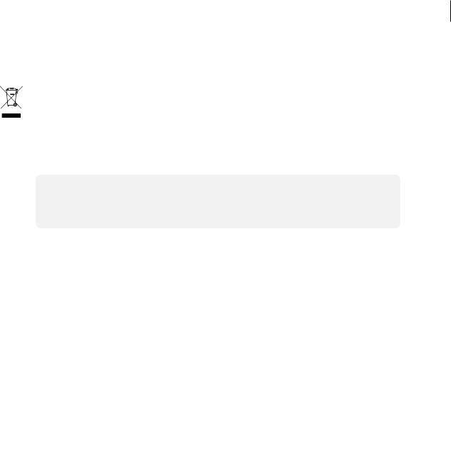
1.3Package Contents
Please check your package contents. Ensure that all of the items are present in your package. If any items are missing or damaged, please contact your dealer immediately.
Atrust t60
Atrust t60 |
AC adapter |
Quick Start Guide |
||
|
|
|
|
|
|
|
|
|
|
VESA mount kit (Optional)
NOTE: Your package may not contain a Guide. In this case, a soft copy
hard copy of the Quick Start in PDF format will be provided.
4 Overview
Exterior Views
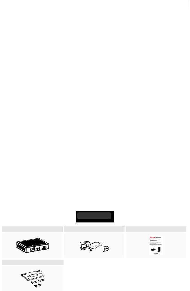
Atrust t62
Atrust t62 |
AC adapter |
DVI-I to VGA adapter |
||||||
|
|
|
|
|
|
|
|
|
|
|
|
|
|
|
|
|
|
|
|
|
|
|
|
|
|
|
|
|
|
|
|
|
|
|
|
|
|
|
|
|
|
|
|
|
Quick Start Guide
NOTE: Your package may not contain a Guide. In this case, a soft copy
hard copy of the Quick Start in PDF format will be provided.
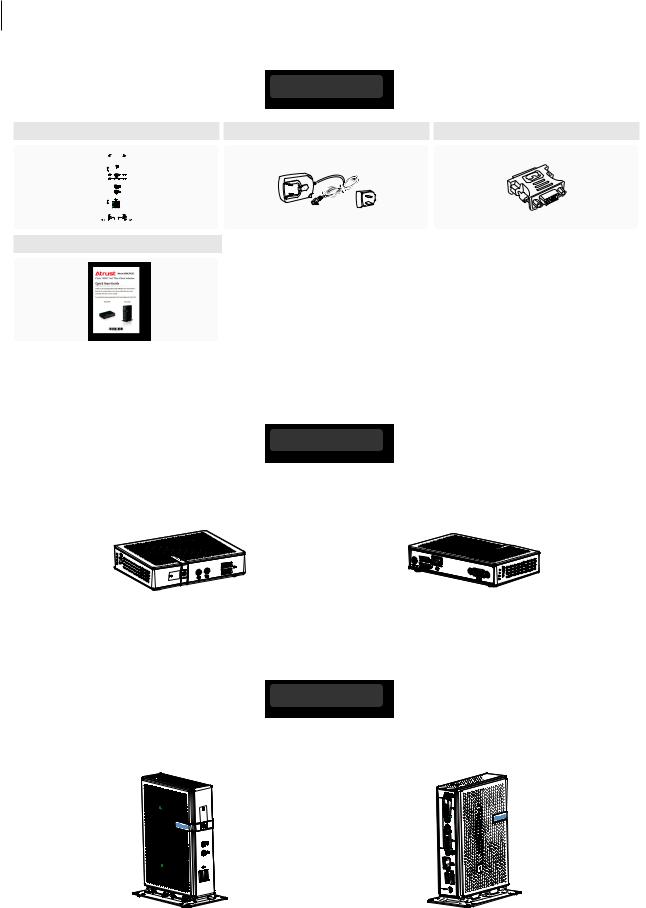
1.4Exterior Views
Atrust t60
Left Front View |
Right Rear View |
Front Panel |
Rear Panel |
Kensington |
|
lock slot |
|||
|
Atrust t62
Left Front View |
Right Rear View |
Front Panel |
Rear Panel |
Overview 5
Panel Components
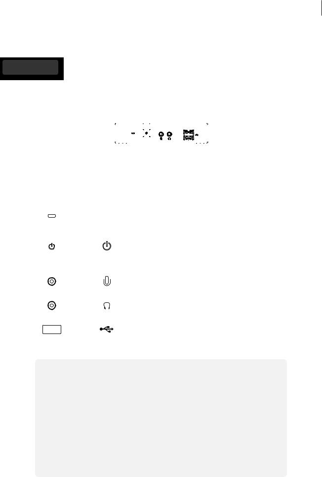
1.5Panel Components
Atrust t60
1 |
4 |
5 |
|
|
|
|
|
|
|
|
|
|
|
|
|
|
|
|
|
|
|
|
|
|
|
|
|
|
|
|
|
|
|
|
|
|
|
|
|
|
|
|
|
|
|
|
|
|
|
|
|
|
|
|
|
|
|
|
|
|
|
|
|
|
|
|
|
|
|
|
|
|
|
|
|
|
|
|
|
|
|
|
|
|
|
|
|
|
|
|
|
|
|
|
|
|
|
|
|
|
|
|
|
|
|
|
|
|
|
|
|
|
|
|
|
|
|
|
|
|
|
|
|
|
|
|
|
|
|
|
|
|
|
|
|
|
|
|
|
|
|
|
|
|
|
|
|
|
|
|
|
|
|
|
|
|
|
|
|
|
|
|
|
|
|
|
|
|
|
|
|
|
|
|
|
|
|
|
|
|
|
|
|
|
|
|
2 |
3 |
|
|
|
|
|
|||||||
|
|
|
|
|
|
|
|
|
|
|
|
|
|
|
|
|
|
|
|
|
|
Front Panel |
|
|
|
|
|
|
|
|
|
|
|
|
|
|
|||||||
|
|
|
|
|
|
|
|
|
|
|
|
|
|
|
|
|
|
|
|
|
|
No. |
Component |
Sign |
Name |
|
|
|
|
Description |
|||||||||||||
|
|
|
|
|
|
|
|
|
|
|
|
|
|
|
|
|
|
|
|
|
|
1 |
|
|
|
|
|
|
|
|
|
|
|
|
|
Power LED |
Indicates the status of power. |
||||||
|
|
|
|
|
|
|
|
|
|
|
|
|
|
|
|
|
|
|
|
|
|
|
|
|
|
|
|
|
|
|
|
|
|
|
|
|
|
|
|
• Press to power on the thin client. |
|||
2 |
|
|
|
|
|
|
|
|
|
|
|
|
Power button |
|
• Long press to force power off the thin client. |
||||||
|
|
|
|
|
|
|
|
|
|
|
|
||||||||||
|
|
|
|
|
|
|
|
|
|
|
|
|
• In Power-off state, connect a monitor to the |
||||||||
|
|
|
|
|
|
|
|
|
|
|
|
|
|
|
|
|
|
||||
|
|
|
|
|
|
|
|
|
|
|
|
|
|
|
|
|
|
client, and then long press 6 to 8 seconds to |
|||
|
|
|
|
|
|
|
|
|
|
|
|
|
|
|
|
|
|
enter Atrust Thin Client Menu. |
|||
|
|
|
|
|
|
|
|
|
|
|
|
|
|
|
|
|
|
|
|
|
|
3 |
|
|
|
|
|
|
|
|
|
|
|
|
Microphone port Connects to a microphone. |
||||||||
|
|
|
|
|
|
|
|
|
|||||||||||||
|
|
|
|
|
|
|
|
|
|
|
|
|
|
|
|
|
|
|
|
|
|
|
|
|
|
|
|
|
|
|
|
|
|
|
|
|
|
|
|
|
|
|
|
4 |
|
|
|
|
|
|
|
|
|
|
|
|
Headphone port |
Connects to a set of headphones or |
|||||||
|
|
|
|
|
|
|
|
|
|
|
|
|
|
|
|
|
a speaker system. |
||||
|
|
|
|
|
|
|
|
|
|
|
|
|
|
|
|
|
|
|
|
|
|
5 |
|
|
|
|
|
|
|
|
|
|
|
|
|
USB port |
Connects to a USB device. |
||||||
|
|
|
|
|
|
|
|
|
|
|
|
|
|||||||||
|
|
|
|
|
|
|
|
|
|
|
|
|
|
|
|
|
|
|
|
|
|
NOTE
• Six options are available on Atrust Thin Client Menu (see the table below). For more information, please refer to “Appendices” on page 169.
Menu Option |
Description |
|
|
Normal Mode |
Boots up your t60/t62 as the normal startup procedure. |
|
|
Safe Mode |
Clears and resets the current screen resolution setting. |
|
|
Reset Mode |
Resets your t60/t62 to the factory default. |
|
|
Firmware update |
Updates firmware for your t60/t62. |
|
|
Reboot |
Reboots your t60/t62. |
|
|
Shutdown |
Shuts down your t60/t62. |
|
|
6 Overview
Panel Components
Atrust t60
7 9
6 |
10 |
8
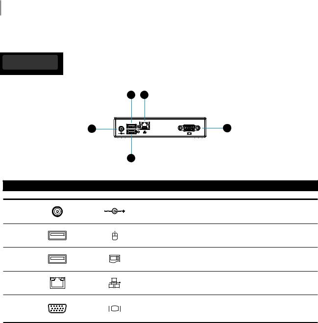
Rear Panel
No. |
Panel Component |
Sign |
Component Name |
Description |
6 |
|
|
DC IN |
Connects to an AC adapter. |
7 |
|
|
USB port |
Connects to a mouse. |
8 |
|
|
USB port |
Connects to a keyboard. |
9 |
|
|
LAN port |
Connects to a network. |
10 |
|
|
VGA port |
Connects to a monitor. |
Overview 7
Panel Components
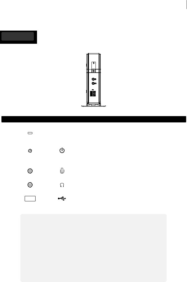
Atrust t62
1
2
3
4
5
Front Panel
No. |
Component |
Sign |
Name |
Description |
||||||||
|
|
|
|
|
|
|
|
|
|
|
|
|
1 |
|
|
|
|
|
|
|
|
|
|
Power LED |
Indicates the status of power. |
|
|
|
|
|
|
|
|
|
|
|
|
|
|
|
|
|
|
|
|
|
|
|
|
|
• Press to power on the thin client. |
2 |
|
|
|
|
|
|
|
|
|
|
Power button |
• Long press to force power off the thin client. |
|
|
|
|
|
|
|
|
|
|
|||
|
|
|
|
|
|
|
|
|
|
• In Power-off state, connect a monitor to the |
||
|
|
|
|
|
|
|
|
|
|
|
|
|
|
|
|
|
|
|
|
|
|
|
|
|
client, and then long press 6 to 8 seconds to |
|
|
|
|
|
|
|
|
|
|
|
|
enter Atrust Thin Client Menu. |
|
|
|
|
|
|
|
|
|
|
|
|
|
3 |
|
|
|
|
|
|
|
|
|
|
Microphone port Connects to a microphone. |
|
|
|
|
|
|
|
|
|
|
|
|||
|
|
|
|
|
|
|
|
|
|
|
|
|
|
|
|
|
|
|
|
|
|
|
|
|
|
4 |
|
|
|
|
|
|
|
|
|
|
Headphone port |
Connects to a set of headphones or |
|
|
|
|
|
|
|
|
|
|
|
|
a speaker system. |
|
|
|
|
|
|
|
|
|
|
|
|
|
5 |
|
|
|
|
|
|
|
|
|
|
USB port |
Connects to a USB device. |
|
|
|
|
|
|
|
|
|
|
|||
|
|
|
|
|
|
|
|
|
|
|
|
|
NOTE
• Six options are available on Atrust Thin Client Menu (see the table below). For more information, please refer to “Appendices” on page 169.
Menu Option |
Description |
|
|
Normal Mode |
Boots up your t60/t62 as the normal startup procedure. |
|
|
Safe Mode |
Clears and resets the current screen resolution setting. |
|
|
Reset Mode |
Resets your t60/t62 to the factory default. |
|
|
Firmware update |
Updates firmware for your t60/t62. |
|
|
Reboot |
Reboots your t60/t62. |
|
|
Shutdown |
Shuts down your t60/t62. |
|
|
8 Overview
Panel Components
Atrust t62
6
7
8
9
10
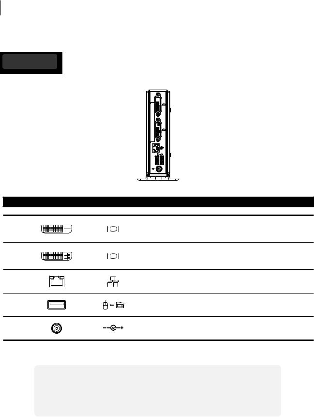
Rear Panel
No. |
Panel Component |
Sign |
Component Name |
Description |
|
|
|
|
Connects to a high quality digital display |
6 |
|
|
DVI-D port |
device such as a LCD monitor or |
|
|
|
|
a digital projector. |
|
|
|
|
Connects to a high quality digital display |
7 |
|
|
DVI-I port |
device such as a LCD monitor or |
|
|
|
|
a digital projector. |
8 |
|
|
LAN port |
Connects to a network. |
9 |
|
|
USB port |
Connects to a keyboard or mouse. |
10 |
|
|
DC IN |
Connects to an AC adapter. |
NOTE
• Your t62 comes with a DVI-I to VGA adapter. If only the VGA monitor is available, use the supplied DVI-I to VGA adapter to connect your VGA monitor to t62’s DVI-I port. For detailed instructions, please see section “2.4 Getting Connected” on page 19.

Overview 9
LED Indicators
1.6LED Indicators
Your t60/t62 is equipped with a Power LED to indicate the state of power. The meanings of LED signals are described as follows:
LED |
Signal |
Meaning |
|
|
|
|
|
Power LED |
Off |
The client is off. |
|
|
|
||
Blue |
The client is on. |
||
|
|||
|
|
|
The LAN port of your t60/t62 has two LED indicators showing the state of networking. The meanings of LED signals are described as follows:
|
Left LED |
Right LED |
Meaning |
|
|
(transmission rate) |
(transmission activity) |
||
|
|
|||
|
|
|
|
|
|
Off |
Off |
The client is not connected to a LAN. |
|
|
|
|
|
|
LED Signal |
Off |
Amber blinking |
The client connects to a 10 Mbps LAN. |
|
|
|
|
||
Orange |
Amber blinking |
The client connects to a 100 Mbps LAN. |
||
|
||||
|
|
|
|
|
|
Green |
Amber blinking |
The client connects to a 1000 Mbps LAN. |

10 Overview
2
Setting Up Your t60/t62
This chapter provides detailed instructions on how to set up your t60/t62 thin clients.
2.1 Positioning Your t60 |
|
To mount your t60 |
|
Step 1: Understand Your VESA Mount Kit for t60 |
13 |
Step 2: Mount Your t60 |
14 |
2.2 Positioning Your t62 |
|
To mount your t62 |
|
Step 1: Remove the Stand from Your t62 |
15 |
Step 2: Understand Your Stand / VESA Mount Kit for t62 |
16 |
Step 3: Store Screws inside the Bracket |
17 |
Step 4: Remove Screws from the Bracket |
17 |
Step 5: Mount Your t62 |
18 |
2.3 |
Assembling the AC Adapter |
|
|
How to assemble the AC adapter and its detached plug |
18 |
2.4 |
Getting Connected |
|
|
How to connect peripherals and power for t60/t62 |
19 |

Setting Up Your t60/t62 13
Positioning Your t60
2.1Positioning Your t60
There are two ways to position your t60:
•Put it on a desk or a desired place horizontally.
•Mount it on the back of a monitor using a VESA mount kit.
NOTE
• The VESA mount kit is an optional accessory for your t60. Your package may not contain a VESA mount kit. Contact your dealer if needed.
To mount your t60 on the back of a monitor, please follow the steps below:
Step 1: Understand Your VESA Mount Kit for t60
Step 2: Mount Your t60
Step 1: Understand Your VESA Mount Kit for t60
Your t60’s VESA mount kit consists of a bracket and six screws.
Mount bracket
Six screws with two types
Mount Bracket for t60
Refer to the following figure and descriptions for the VESA mount holes on the mount bracket for t60.
1 |
1 |
2 |
2 |
3 |
3 |
Mount Hole Description
1The VESA mount holes used to secure the bracket to your t60.
2The VESA mount holes (with the distance of 100 mm) used to secure the bracket to a monitor.
3The VESA mount holes (with the distance of 75 mm) used to secure the bracket to a monitor.
14 Setting Up Your t60/t62
Positioning Your t60
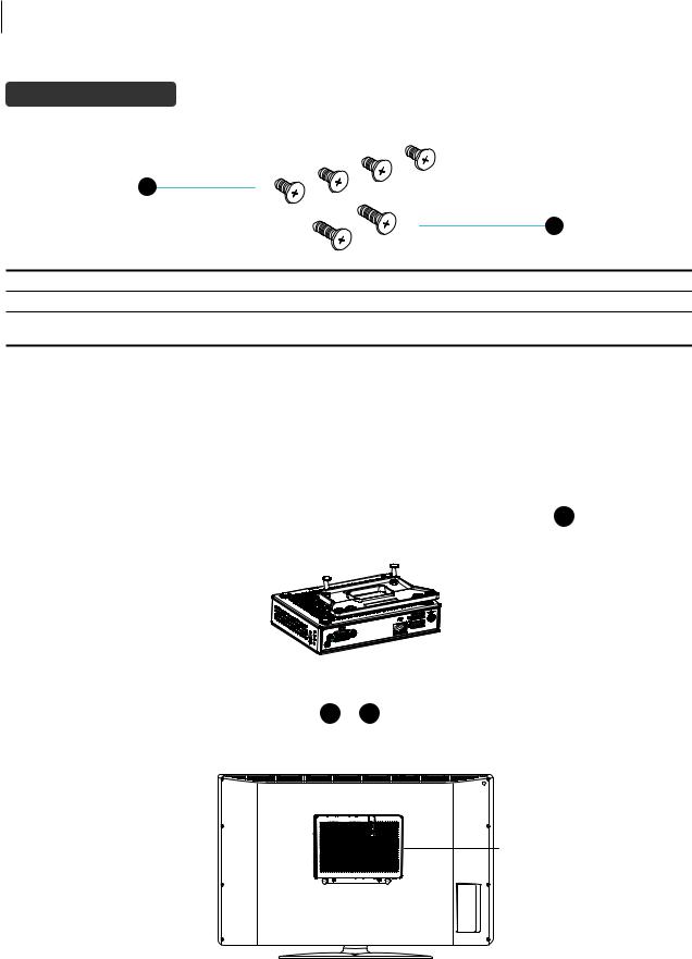
Mount Screws for t60
1
|
|
2 |
|
Screw Type |
Number |
Description |
|
1 |
4 |
The screws used to secure the bracket to your t60 and to a monitor. |
|
2 |
2 |
The longer screws used to secure the bracket to a monitor if the screws of type 1 |
|
cannot firmly secure the bracket and your t60 to the monitor. |
|||
|
|
Step 2: Mount Your t60
To mount your t60 on the back of the monitor, please do the following:
1.Place your t60 on a flat surface with the VESA mount hole side upward.
2.With the bracket side marked with Atrust facing downward, align two mount holes on the bracket with two
mount holes on your t60 such that the bracket projects out and is closer to the rear panel than the front one as shown below, and then secure the bracket to your t60 with two (2) screws of type 1 .
3. Align the mount holes on the bracket with the mount holes on the back of the monitor, and then secure the
bracket to the monitor with two (2) screws of 1 or 2 . Ensure that the rear panel of your t60 is facing downward as shown below.
Have t60’s rear panel facing downward.

Setting Up Your t60/t62 15
Positioning Your t62
2.2Positioning Your t62
There are two ways to position your t62:
•Put it (with its stand) on a desk or a desired place uprightly.
•Mount it on the back of a monitor using a VESA mount kit.
To mount your t62 on the back of a monitor, please follow the steps below:
Step 1: Remove the Stand from Your t62
Step 2: Understand Your Stand / VESA Mount Kit for t62
Step 3: Store Away Screws inside the Bracket
Step 4: Remove Screws from the Bracket
Step 5: Mount Your t62
Step 1: Remove the Stand from Your t62
To remove the stand from your t62, please do the following:
1. Place your t62 on a flat surface with the stand side upward. 2. Remove the screw that fixes the stand to your t62.
3. Store away the removed screw inside the stand. Detailed instructions will be provided in Step 2 and 3.
NOTE
• It’s highly recommended to store screws away inside the stand when not needed to prevent them getting lost.

16 Setting Up Your t60/t62
Positioning Your t62
Step 2: Understand Your Stand / VESA Mount Kit for t62
The stand for your t62 is dual-purpose: it can be used as a stand or as a VESA mount kit. All screws of different types supplied with the stand / VESA mount kit can be stored away inside the main bracket when not needed.
Screws Stored Away inside the Bracket
The following figure shows different types of screws stored away inside the main bracket.
Dual-purpose
bracket
1 |
1 |
2 |
2 |
3 |
Screw Type |
Number |
Description |
|
|
|
|
|
1 |
2 |
The largest-size screws used to secure the bracket to a monitor as a VESA mount if |
|
the middle-size screws cannot firmly secure the bracket and your t62 to the monitor. |
|||
|
|
||
|
|
|
|
2 |
4 |
The middle-size screws used to secure the bracket to your t62 and to a monitor when |
|
using the bracket as a VESA mount. |
|||
|
|
||
|
|
|
|
3 |
1 |
The smallest-size screw used to secure the bracket to your t62 as a stand. |
|
|
|
|
Mount Holes on the Bracket
Refer to the following figure and descriptions for the VESA mount holes on the bracket.
1 |
1 |
2 |
2 |
2 |
2 |
1 |
1 |
Mount Hole Description
1The VESA mount holes used to secure the bracket to a monitor (only two of them will be used).
2The VESA mount holes used to secure the bracket to your t62 (only two of them will be used).

Setting Up Your t60/t62 17
Positioning Your t62
Step 3: Store Screws inside the Bracket
To store screws inside the bracket, please do the following:
NOTE
• It’s highly recommended to store screws inside the bracket when not needed to prevent them getting lost.
1.Place a sheet of paper or a piece of cloth on a flat surface, and then put your bracket on that paper or cloth with the screw storage side upward.
2.Place the screw upon its storage space, and push the screw into the space with your finger until it clicks into place. For the smallest-size screw, use the tip of a screwdriver instead to push the screw.
NOTE
• Please refer to the figure and descriptions in “Step 2: Understand Your Stand / VESA Mount Kit for t62” for the correct storage space of each screw.
Step 4: Remove Screws from the Bracket
To remove screws stored inside the bracket, please do the following:
1.Place a sheet of paper or a piece of cloth on a flat surface, and then put your bracket on that paper or cloth with the screw storage side downward.
2.Insert the tip of a screwdriver into the square holes to remove the desired screws from the bracket.

 Square Hole
18 Setting Up Your t60/t62
Assembling the AC Adapter
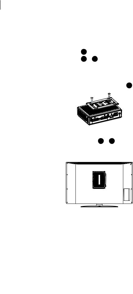
Step 5: Mount Your t62
To mount your t62 on the back of a monitor, please do the following:
1. Refer to Step 2 and Step 4 to prepare required screws for mounting your t62.
• |
You will need two (2) screws of type |
2 |
to secure the bracket to your t62. |
• |
You will need two (2) screws of type |
1 |
or 2 to secure the bracket to the monitor. |
2.Place your t62 on a flat surface with the VESA mount hole side upward.
3.Refer to Step 2 to choose two of the four VESA mount holes on the bracket to align with two mount holes on your t62 such that the bracket projects out and is closer to the rear panel than the front one as shown below, and then secure the bracket to your t62 with two (2) screws of type 2 .
4. Align the mount holes on the bracket with the mount holes on the back of the monitor, and then secure the
bracket to the monitor with two (2) screws of type 2 or 1 . Ensure that your t62 is located in the center of the monitor and the rear panel of your t62 is facing rightward as shown below.
Have t62’s rear panel facing rightward.
2.3Assembling the AC Adapter
To assemble the AC adapter for your t60/t62, please do the following:
1.Unpack your thin client package and take out the AC adapter and its detached plug.
2.Slide the plug into the AC adapter until it clicks into place.
NOTE
• The supplied plug may vary, depending on different areas.

Setting Up Your t60/t62 19
Getting Connected
2.4Getting Connected
To make connections for your t60/t62, please do the following:
1.Connect your t60/t62 to your local network with an Ethernet cable.
2.Connect a keyboard and mouse to your t60/t62.
3.Connect and turn on the monitor(s).
NOTE
• For your t62, if only the VGA monitor is available, use the supplied DVI-I to VGA adapter to connect your t62 and monitor.
DVI-I port (t62 only)
DVI-I to VGA |
VGA cable |
|
|
adapter |
|
•Please note that you need to connect and turn on your monitor(s) before powering up your thin client. Otherwise, the client may fail to set
an appropriate resolution for the monitor(s).
4.Connect your t60/t62 to a power outlet using the AC adapter included in the package.
NOTE
• For detailed instructions on how to assemble the supplied AC adapter, please refer to section “2.3 Assembling the AC Adapter” on page 18.
5. Connect other peripherals for your t60/t62 if needed.

20 Setting Up Your t60/t62
 Loading...