

Page 1

Atrust m320
for Windows® MultiPoint® Server 2012
User’s Manual
Internal Draft 0.01
© 2013-14 Atrust Computer Corp.
Page 2

UM-m320-WMS12-EN-14012810
Page 3

Copyright and Trademark Statements
© 2013-14 Atrust Computer Corp. All rights reserved.
This document contains proprietary information that is protected by copyright. No part of this document may be
photocopied, reproduced, or translated to another language without the prior written consent of Atrust Computer
Corp.
Limitation of Liability
While reasonable eorts have been made to ensure the accuracy of this manual, the manufacturer and distributor
assume no liability resulting from errors or omissions in this manual , or from the use of the information contained
herein.
Trademark statements
Microsoft, Windows, and MultiPoint are trademarks of the Microsoft group of companies.
Other product names mentioned herein are used for identication purposes only and may be trademarks and/or
registered trademarks of their respective companies.
i
Page 4
ii
About This User’s Manual
This manual provides information on how to set up and use Atrust m320 zero clients (multifunction station hubs) as
LAN-based stations for Windows® MultiPoint® Server 2012.
Manual Structure and Subjects
Chapter Subject
1 Provides an overview of Atrust m320 zero clients for Windows
2 Gives detailed instructions on how to set up your m320.
3 Provides information on getting your m320 ready for use.
4 Provides information on how to manage your m320.
Specications Lists and provides detailed information on key components of your m320.
®
MultiPoint® Server 2012.
Notes, Tips, and Warnings
Throughout this manual, the notes, tips, and warnings in the following formats are used to provide important
information, useful advice, and prevent injuries to you, damage to your devices, or loss of data on your system.
NOTE
• A note provides important information for a specic situation.
TIP
• A tip gives a piece of useful advice to perform a task more eciently.
WARNING
• A warning provides crucial information that must be followed to prevent injuries to
you, damage to your devices, or loss of data on your system.
Style Conventions
The following styles are used throughout this manual while referring to operational items on input devices,
hardware panels, or application interfaces.
Item Style Example
keys on the keyboard bold Ctrl+Alt+Delete, N, B, S
system modes rst letter capitalized Console mode, Station mode
application windows or menus rst letter capitalized Initial Setup window, General Task menu
buttons or tabs on a window, toolbars,
taskbar, or menu
options on a window, screen, list, or menu bold LAN Station Driver and Utility, Use DHCP
bold OK, Finish, Start, LAN Stations tab
Page 5

Safety and Regulatory Information
Regulatory Statement
Federal Communications Commission Interference Statement
This equipment has been tested and found to comply with the limits for a Class B digital device, pursuant to Part
15 of the FCC Rules. These limits are designed to provide reasonable protection against harmful interference in a
residential installation. This equipment generates, uses and can radiate radio frequency energy and, if not installed
and used in accordance with the instructions, may cause harmful interference to radio communications. However,
there is no guarantee that interference will not occur in a particular installation. If this equipment does cause
harmful interference to radio or television reception, which can be determined by turning the equipment o and
on, the user is encouraged to try to correct the interference by one of the following measures:
• Reorient or relocate the receiving antenna.
• Increase the separation between the equipment and receiver.
• Connect the equipment into an outlet on a circuit dierent from that to which the receiver is connected.
• Consult the dealer or an experienced radio/TV technician for help.
iii
FCC Caution: Any changes or modications not expressly approved by the party responsible for compliance could
void the user’s authority to operate this equipment. This device complies with Part 15 of the FCC Rules. Operation is
subject to the following two conditions: (1) This device may not cause harmful interference, and (2) this device must
accept any interference received, including interference that may cause undesired operation.
IMPORTANT NOTE:
FCC Radiation Exposure Statement
This equipment complies with FCC radiation exposure limits set forth for an uncontrolled environment. This
equipment should be installed and operated with minimum distance 20 cm between the radiator & your body.
This transmitter must not be co-located or operating in conjunction with any other antenna or transmitter.
Page 6
iv
Regulatory Information
WEEE (Waste Electrical and Electronic Equipment) Directive
In the European Union, this symbol indicates that this product should not be disposed of with
household waste. It should be deposited at an appropriate facility to enable recovery and recycling.
Safety Information
For proper disposal, please contact your local recycling or hazardous waste center.
WARNING
• Use only power supplies listed in the user instructions.
WARNING
• Don’t use a keyboard and mouse that in total require more than 200 mA of rated
current during operation.
WARNING
• For safety, do not make mechanical or electrical modications to the equipment.
• Do not remove equipment covers and access any of the components inside the
equipment. Any access inside the equipment without an authorized or certied
technician may cause serious injuries and damage. For any problem, contact your
dealer for assistance.
• You should only make repairs as authorized by the product documentation.
Repairs, replacement, expansion, and upgrades not performed by a certied service
technician may cause injuries to you, damage your system, and void your warranty.
Page 7

Table of Contents
Copyright and Trademark Statements i
Limitation of Liability i
Trademark statements i
About This User’s Manual ii
Manual Structure and Subjects ii
Notes, Tips, and Warnings ii
Style Conventions ii
Safety and Regulatory Information iii
Regulatory Statement iii
Regulatory Information iv
Safety Information iv
1 Overview 1
1.1 Introduction 3
1.2 Features 3
v
1.3 Package Contents 4
1.4 Exterior Views 4
1.5 Panel Components 5
1.6 LED Indicators 7
2 Setting Up Your m320 9
2.1 Positioning Your m320 11
2.2 Getting Connected 13
3 Getting Your m320 Ready for Use 17
3.1 Getting Stations Ready for Use 19
3.2 Installing Drivers and the Utility 19
3.3 Initial Setup 20
3.4 Updating Drivers and the Utility 24
4 Managing Your LAN Stations 27
4.1 LAN Stations tab Overview 29
4.2 Available Tasks at a Glance 30
4.3 Taking Over a Failed Host 31
4.4 Serving Orphaned LAN Stations 32
4.5 Scanning Free LAN Stations 33
4.6 Renaming a LAN Station 33
4.7 Adjusting Network Settings for a LAN Station 34
4.8 Changing the Password for a LAN Station 36
Page 8

vi
4.9 Identifying a LAN Station with its Power LED 36
4.10 Assigning a LAN Station to a Local Host Server 37
4.11 Clearing the Host Server Assignment for a LAN Station 37
Specications 39
Page 9

Overview
1
This chapter provides an overview of Atrust m320 zero clients
for Windows® MultiPoint® Server 2012.
1.1 Introduction
®
Windows
Atrust shared resource solution
1.2 Features
the features of Atrust system solution 3
1.3 Package Contents
check your package contents 4
1.4 Exterior Views
overview of device outside elements 4
MultiPoint Server 2012 and
3
1.5 Panel Components
detailed descriptions of front and rear panel
components
1.6 LED Indicators
descriptions of signals for LED indicators 7
5
Page 10

Page 11

Overview
Introduction
1.1 Introduction
Windows® MultiPoint® Server 2012 is a new shared resource technology. This Windows-based operating system
enables a host server to power multiple and independent stations, allowing users to share the computing power
of one single server. With the same budget, this shared resource mode provides more people with access to
computing than the traditional single-user mode.
Based on Windows® MultiPoint® Server 2012, Atrust oers an integrated system solution incorporating both the
server and station sides. Your Atrust m320 zero clients (multifunction station hubs) are used to deploy stations and
support the LAN-based connection method to the host server.
1.2 Features
Atrust solution enables educators to:
• Drastically reduce the total cost of ownership
• Allocate more money to other resources for learning
3
• Provide a familiar and independent Windows experience
• Multiply computing access for students
• Easily set up, manage, and maintain the whole system
This shared resource solution is also perfectly suited for small businesses who are looking for:
• Cost-eective and exible IT solution that can easily expand when business grows
• Manageable IT solution without a lot of manpower
• Secure, reliable and stable solution
• Stable-enhanced system with ECC (Error Checking and Correcting) memory support
• Familiar Microsoft Windows operating environment
• Windows-compatible solution for business and productivity software
Key features at a glance:
• Broad support for diverse connection methods – USB-based (m300 / m302), LAN-based (m320), and
RDP-based (t-series thin clients) stations
• Manage multiple MultiPoint® Sever systems on a single computer
• Arrange stations for a specic purpose, like public access to library service, using the auto-logon feature
• Add a new station by sharing an existing station monitor with the split screen feature
• Monitor and control station usage with the session monitoring, web limiting,
and application launching/closing features
• Share any session across all stations by the session broadcast feature
• Orchestrate activities and draw attention in class with the help of the station blocking
and message display features
Page 12
Overview
4
Package Contents
1.3 Package Contents
Please check your package contents. Ensure that all of the items are present in your package(s). If any items are
missing or damaged, please contact your dealer immediately.
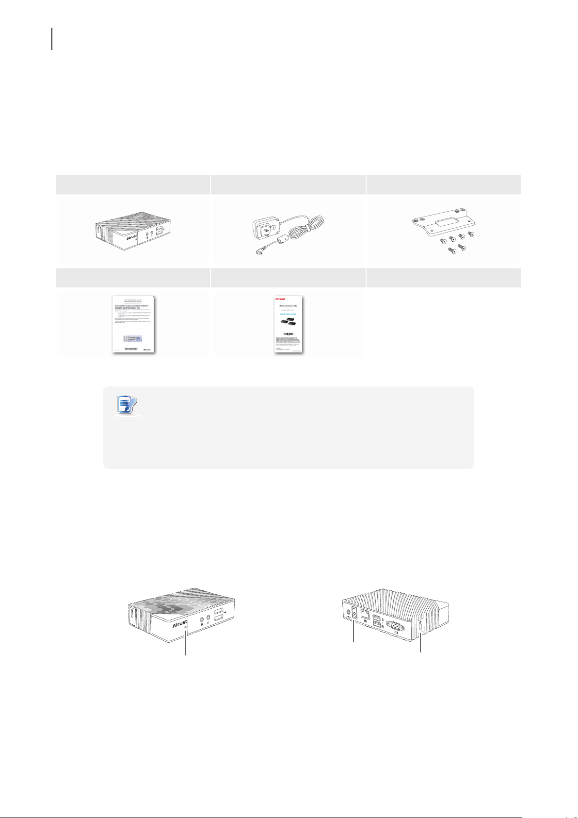
Your client package comes with the following items. The number of clients and accessories may vary, depending on
your package deal.
Atrust m320 AC adapter VESA mount kit (optional)
CAL with the COA label Quick Setup Guide
NOTE
• Your deal may not contain an OEM Windows MultiPoint Server 2012 CAL. To obtain
a license, please refer to Microsoft web pages at:
http://www.microsoft.com/windows/multipoint/buy.aspx or
http://www.microsoft.com/windows/multipoint/default.aspx.
1.4 Exterior Views
Left Front View
Front Panel
Right Rear View
Rear Panel
Kensington
Security Slot
Page 13
Panel Components
1.5 Panel Components
Atrust m320
2
4
1
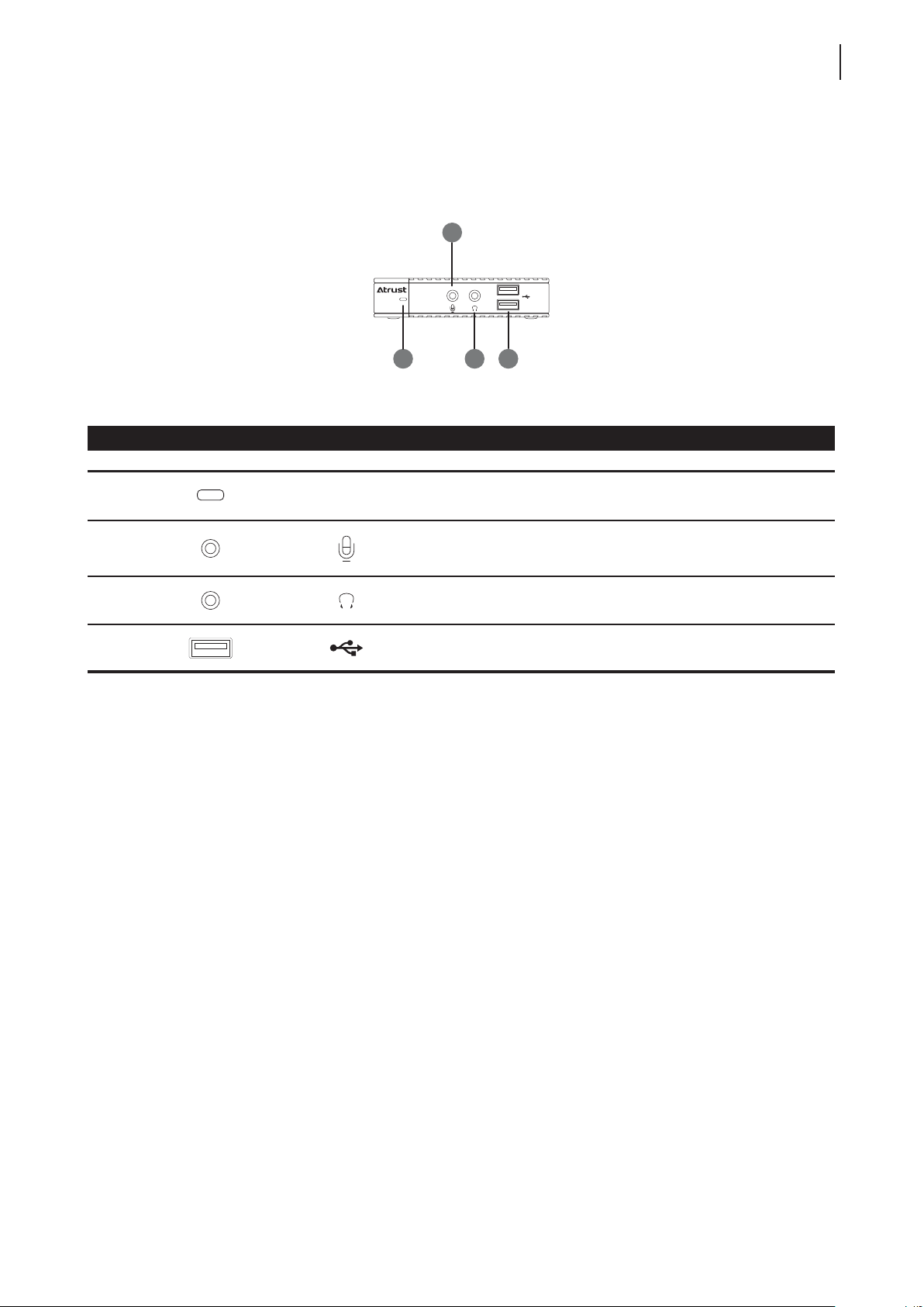
Front Panel Components
No. Component Sign Name Description
3
Overview
5
1
2
3
4
Power LED Indicates the status of power.
Microphone port Connects to a microphone.
Headphone port
USB port Connects to a USB device.
Connects to a set of headphones or a
speaker system.
Page 14
Overview
6
Panel Components
Atrust m320
5
6
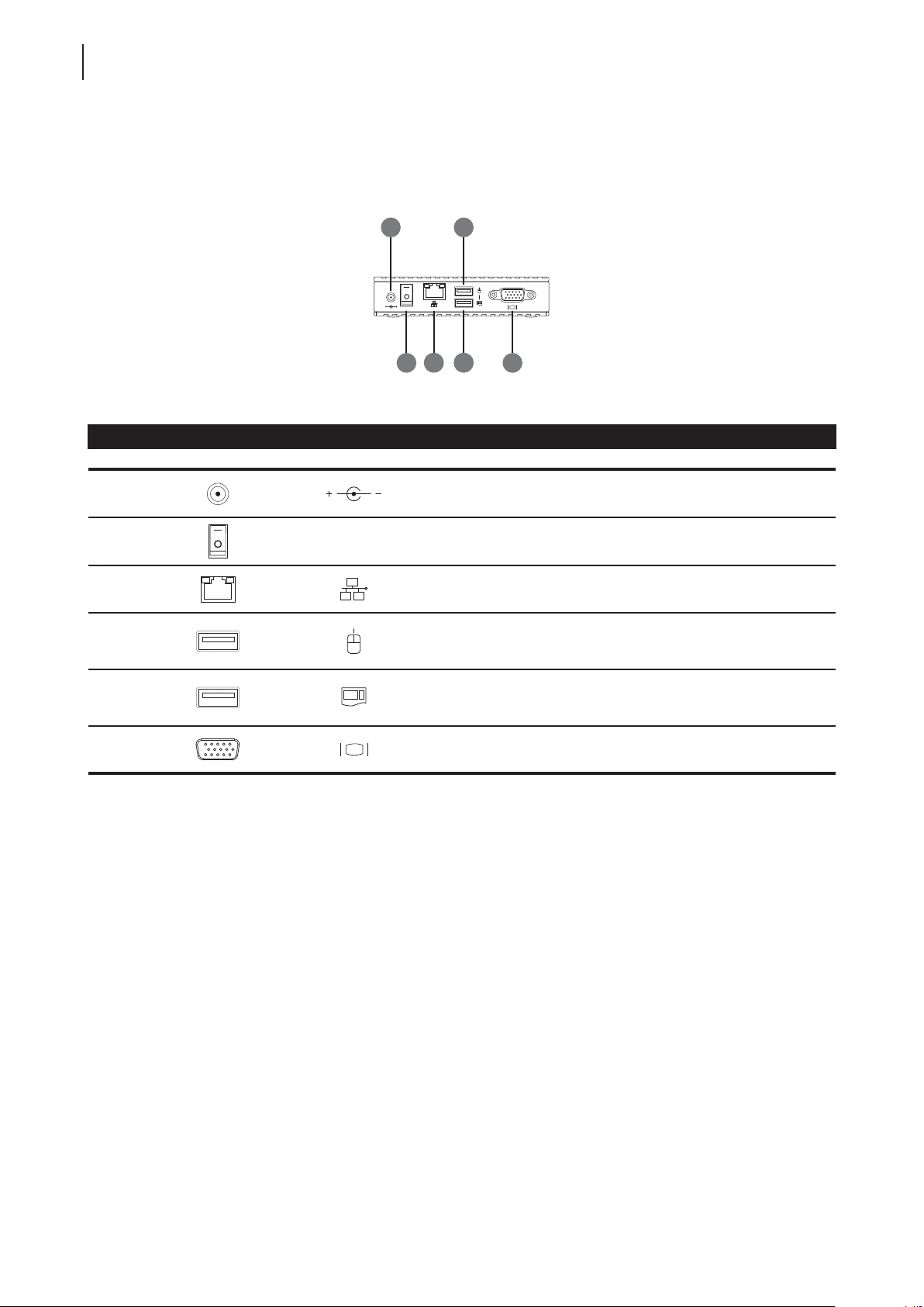
Rear Panel Components
No. Panel Component Sign Component Name Description
5
6
7
8
8
9
7
Power switch Press to turn on / off the client.
10
DC IN Connects to an AC adaptor.
LAN port
USB port Connects to a mouse.
Connects to a host server through a
Gigabit switch.
1
9 USB port Connects to a keyboard.
10 VGA port Connects to a monitor.
1
Don’t use a keyboard and mouse that in total require more than 200 mA of rated current during operation.
1
Page 15

Overview
LED Indicators
1.6 LED Indicators
Your m320 is equipped with a Power LED to indicate the state of power. The meanings of LED signals are
described as follows:
LED Signal Meaning
Off The client is off.
Power LED
Blue The client is on.
Blue blinking The Identify station with LED function is active.
NOTE
• For instructions on how to identify stations with their Power LED, please refer to
section “4.9 Identifying a LAN Station with its Power LED” on page 36.
7
The LAN port of your m320 has two LED indicators show the state of networking. The meanings of LED signals are
described as follows:
LED Signal
Left LED
(transmission rate)
Off Off The client is not connected to a LAN.
Off Amber blinking The client connects to a 10 Mbps LAN.
Orange Amber blinking The client connects to a 100 Mbps LAN.
Green Amber blinking The client connects to a 1000 Mbps LAN.
Right LED
(transmission activity)
Meaning
Page 16

8
Overview
Page 17

Setting Up Your m320
2
This chapter gives detailed instructions on how to set up your m320
zero client.
2.1 Positioning Your m320
How to position your clients 11
2.2 Getting Connected
Connection with the host - Method 1
Connection with the host - Method 2
Connections with peripherals and the power
13
14
15
Page 18

Page 19
2.1 Positioning Your m320
There are two ways to position your m320:
• Put it on a desk or a desired place horizontally.
• Mount it on the back of a monitor using a VESA mount kit.
NOTE
• The VESA mount kit is an optional accessary for your m320. Your deal may not
contain a VESA mount kit. Contact your dealer if needed.
To mount your m320 on the back of a monitor, please follow the steps below:
Step 1: Understand Your VESA Mount Kit for m320
Setting Up Your m320
Positioning Your m320
11
Step 2: Mount Your m320
Step 1: Understand Your VESA Mount Kit for m320
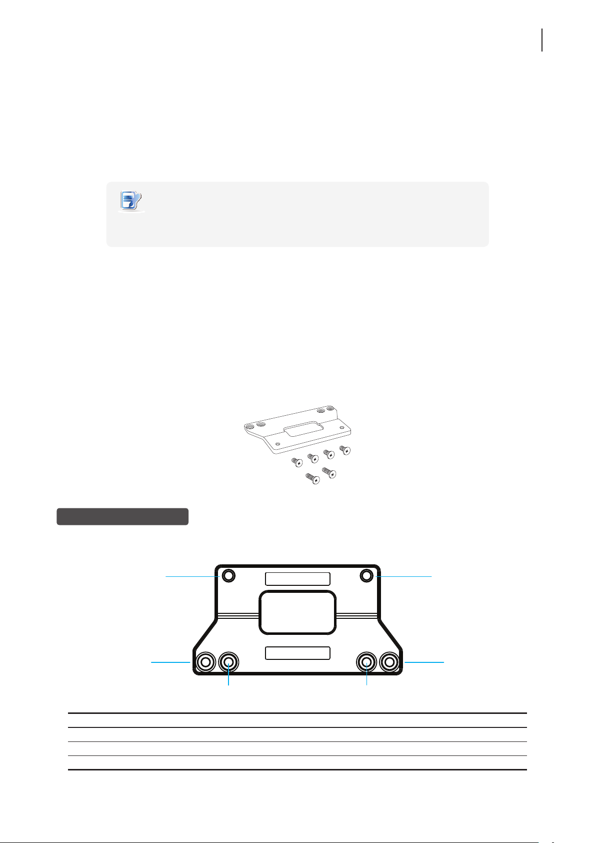
Your m320’s VESA mount kit consists of a bracket and six screws.
Mount bracket
Six screws with
two types
Mount Bracket for m320
Refer to the following gure and descriptions for the VESA mount holes on the mount bracket for m320.
1
1
2
3
Mount Hole Description
1 The VESA mount holes used to secure the bracket to your m320.
2 The VESA mount holes (with the distance of 100 mm) used to secure the bracket to a monitor.
3 The VESA mount holes (with the distance of 75 mm) used to secure the bracket to a monitor.
3
2
Page 20
Setting Up Your m320
1
12
Positioning Your m320
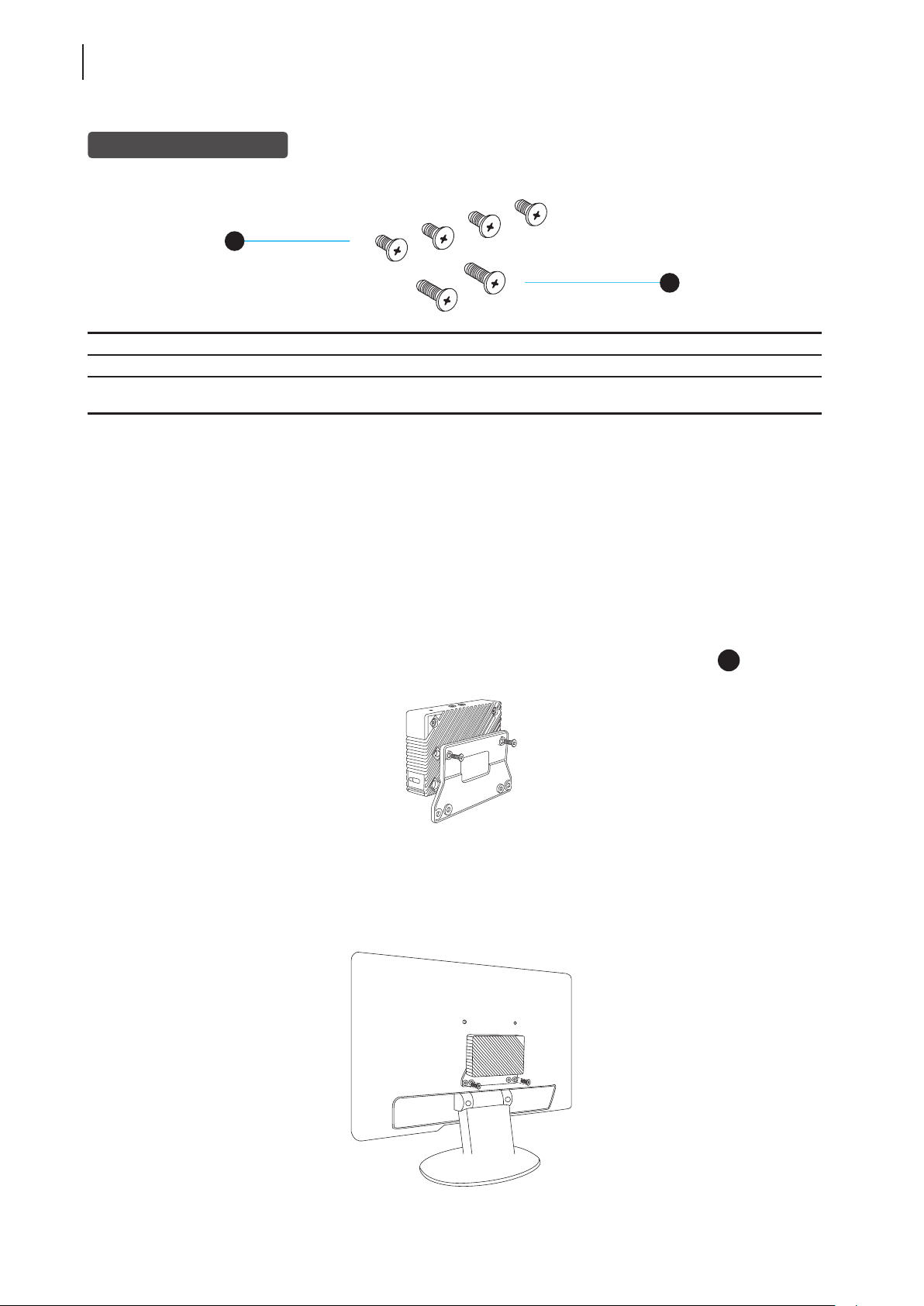
Mount Screws for m320
1
Screw Type Number Description
1 4 The screws used to secure the bracket to your m320 and to a monitor.
2 2
Step 2: Mount Your m320
2
The longer screws used to secure the bracket to a monitor if the screws of type 1
cannot rmly secure the bracket and your m320 to the monitor.
To mount your m320 on the back of the monitor, please do the following:
1. Place your m320 on a at surface with the VESA mount hole side upward.
2. With the rear panel of the client facing downward, secure the VESA mount bracket to the client with two (2)
screws supplied.
3. With the bracket side marked with Atrust facing downward, align two mount holes on the bracket with two
mount holes on your m320 such that the bracket projects out and is closer to the rear panel than the front
one as shown below, and then secure the bracket to your m320 with two (2) screws of type
.
4. Align the bracket holes with the VESA holes on the back of the monitor. Ensure that the rear panel of the
client is facing downward.
5. Secure the VESA mount bracket to the monitor with two (2) screws supplied.
Page 21
Setting Up Your m320
Getting Connected
2.2 Getting Connected
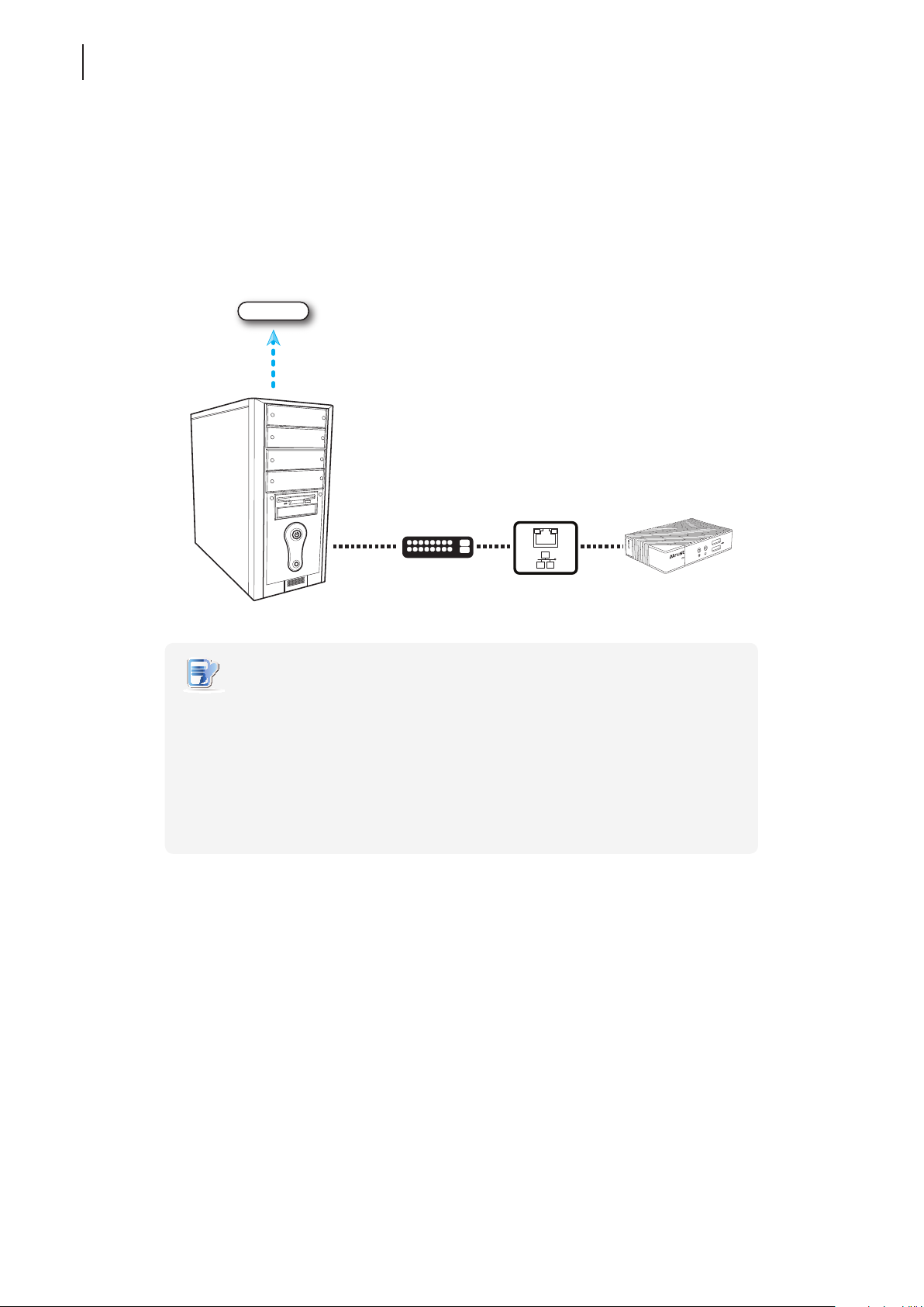
Please follow instructions below to make physical connections for your m320 with the host server, power, and
other peripherals:
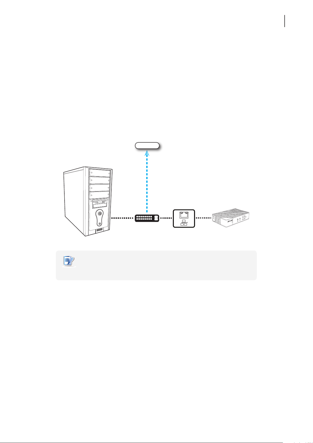
Connection with the Host — Method 1
To make physical Ethernet connection between the host (running Windows® MultiPoint® Server 2012) and your
m320 using method 1, please do the following:
1. Connect both the host and your m320 to the same Gigabit Ethernet switch.
2. Connect the host to a local area network or the Internet through the same Gigabit Ethernet switch.
Local Area Network / Internet
13
Gigabit Switch
NOTE
• It’s recommended to use a Gigabit switch to connect your host and stations.
Page 22
Setting Up Your m320
14
Getting Connected
Connection with the Host — Method 2
To make physical Ethernet connection between the host (running Windows® MultiPoint® Server 2012) and your
m320 using method 2, please do the following:
1. Connect both the host and your m320 to the same Gigabit Ethernet switch.
2. Connect the host to a local area network or the Internet through the host’s second LAN port.
Local Area Network / Internet
Gigabit Switch
NOTE
• If your host computer is equipped with more than one LAN port, you could make
connections using the method 2. No matter which method you use, your m320
will perform network environment detection and choose appropriate network
conguration automatically.
• In case that you need to adjust the network conguration for your m320, please
refer to section “4.7 Adjusting Network Settings for a LAN Station” on page 34.
• It’s recommended to use a Gigabit switch to connect your host server and clients.
Page 23

Setting Up Your m320
Getting Connected
Connections with Peripherals and the Power
To connect peripherals and the power for your m320, please follow the instructions below:
• Display. Connect a monitor to your m320, and turn on the monitor.
• Keyboard and Mouse. Use the USB-based keyboard and mouse.
NOTE
• Please connect the keyboard and mouse to their dedicated USB ports.
• Don’t use a keyboard and mouse that in total require more than 200 mA of rated
current during operation.
• AC Adapter. Use the supplied AC adapter to connect your m320 to a power outlet.
• Audio Input and Output. Connect a microphone, a set of headphones, or a speaker system to your m320.
• Other Peripherals. Connect other USB-based devices to your m320 if needed.
15
Page 24

Setting Up Your m320
16
Page 25

Getting Your m320 Ready for Use
This chapter provides information on how to get your m320 ready for use.
3.1 Getting Stations Ready for Use
how to get m320-based LAN stations ready for use 19
3.2 Installing Drivers and the Utility
how to install the video driver, LAN station driver, and
MultiPoint Manager Add-in for m320-based LAN stations
3.3 Initial Setup
how to create the bonding between the host server and LAN stations 20
3.4 Updating Drivers and the Utility
how to update the video driver, LAN station driver, and
MultiPoint Manager Add-in for m320-based LAN stations
3
19
24
Page 26

Page 27
Getting Your m320 Ready for Use
Getting Stations Ready for Use
3.1 Getting Stations Ready for Use
To get your m320-based LAN stations ready for use, you need to install the video driver, LAN station driver, and
MultiPoint Manager Add-in on your host server where Windows MultiPoint Server 2012 is installed:
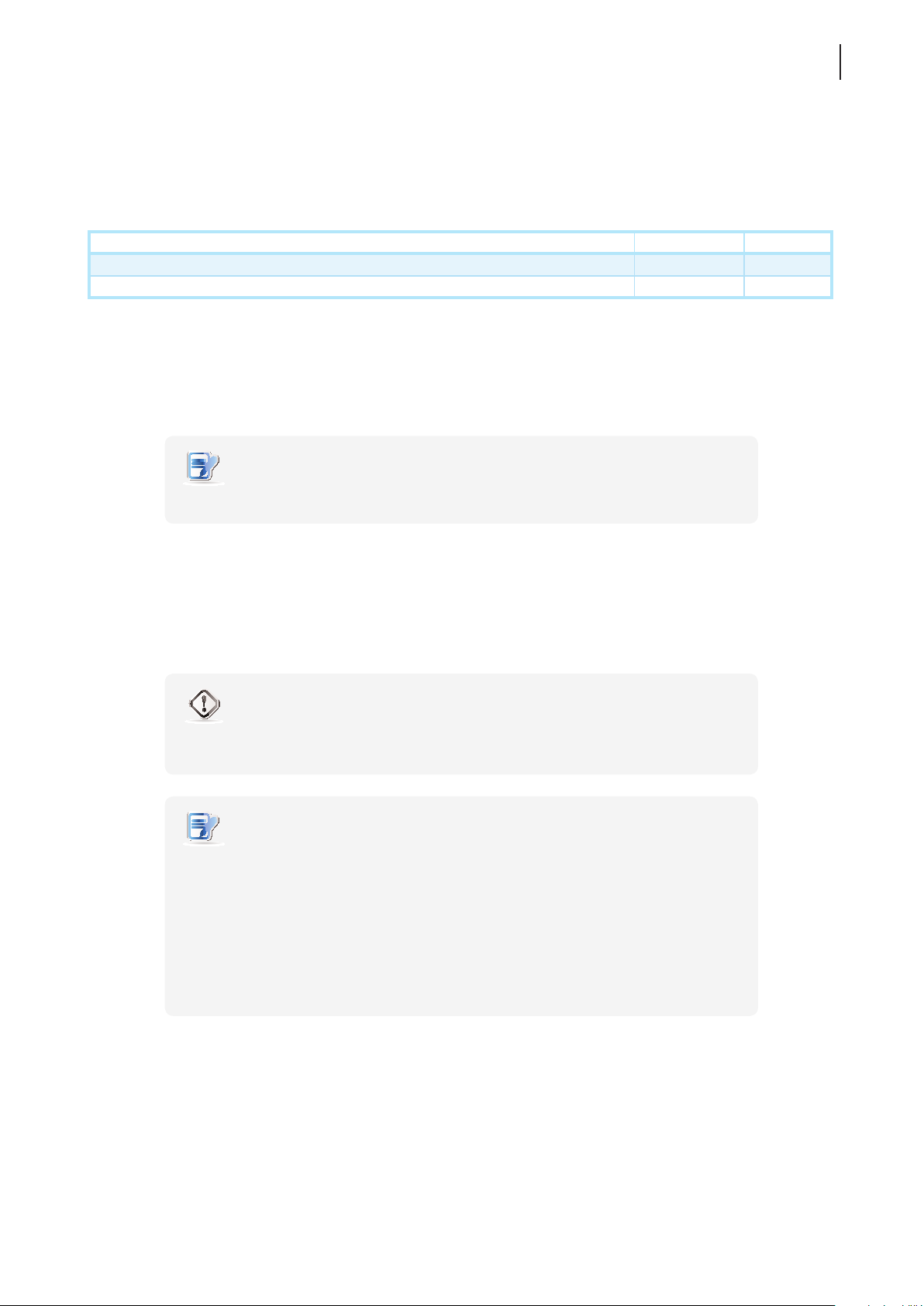
Task Section Page
Installing the video driver, LAN station driver, and MultiPoint Manager Add-in 3.2 19
Initial setup - creating the bonding between the server and LAN stations 3.3 20
3.2 Installing Drivers and the Utility
To install the video driver, LAN station driver, and MultiPoint Manager Add-in on the host server for your m320-based
LAN stations, please do the following:
NOTE
• You will need an administrative account to perform the following tasks.
19
1. Switch your MultiPoint Server system to the Console mode.
2. Disconnect all station hubs if any.
3. Locate Station_Video_Setup_SM_<version>.exe and Station_LAN_Setup_<version>.exe on your
host server and install both in sequence.
WARNING
• Ensure that the WDDM (Windows Display Driver Model) compatible driver is
installed for your host server graphics card before installing the video driver.
NOTE
• You should have got installation programs for drivers and the utility through the
Internet (FTP, email, or website) or a physical CD / DVD. Contact your dealer if
required installation programs are not available.
• If you’ve installed the video driver for your m300 / m302-based USB stations,
you don’t need to install it again.
• To update the video driver, LAN station driver, and MultiPoint Manager Add-in for
your m320-based LAN stations, please refer to section “3.4 Updating Drivers and the
Utility” on page 24.
4. After the installation is completed, switch your MultiPoint Server system to the Station mode.
5. Reconnect all station hubs.
Page 28
Getting Your m320 Ready for Use
20
Initial Setup
3.3 Initial Setup
The bonding between the host server and your m320-based LAN station is created through the Ethernet interface.
Except for this physical connection, to create the bonding between both, you need to assign your LAN station to its
host server. Once the bonding is established, your LAN station is ready for use. Follow the steps below to complete
this initial setup:
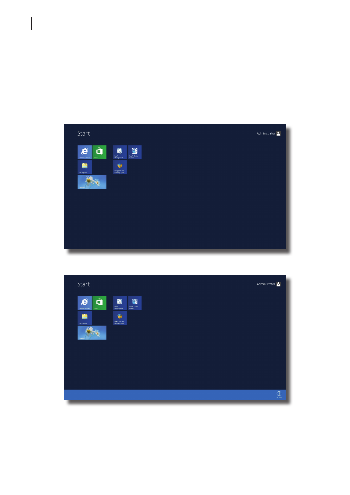
1. On the desired host server, log in with an administrative account.
2. The Start screen appears.
3. Right-click on the Start screen. A blue bar appears on the bottom of the screen.
Page 29
Getting Your m320 Ready for Use
Initial Setup
21
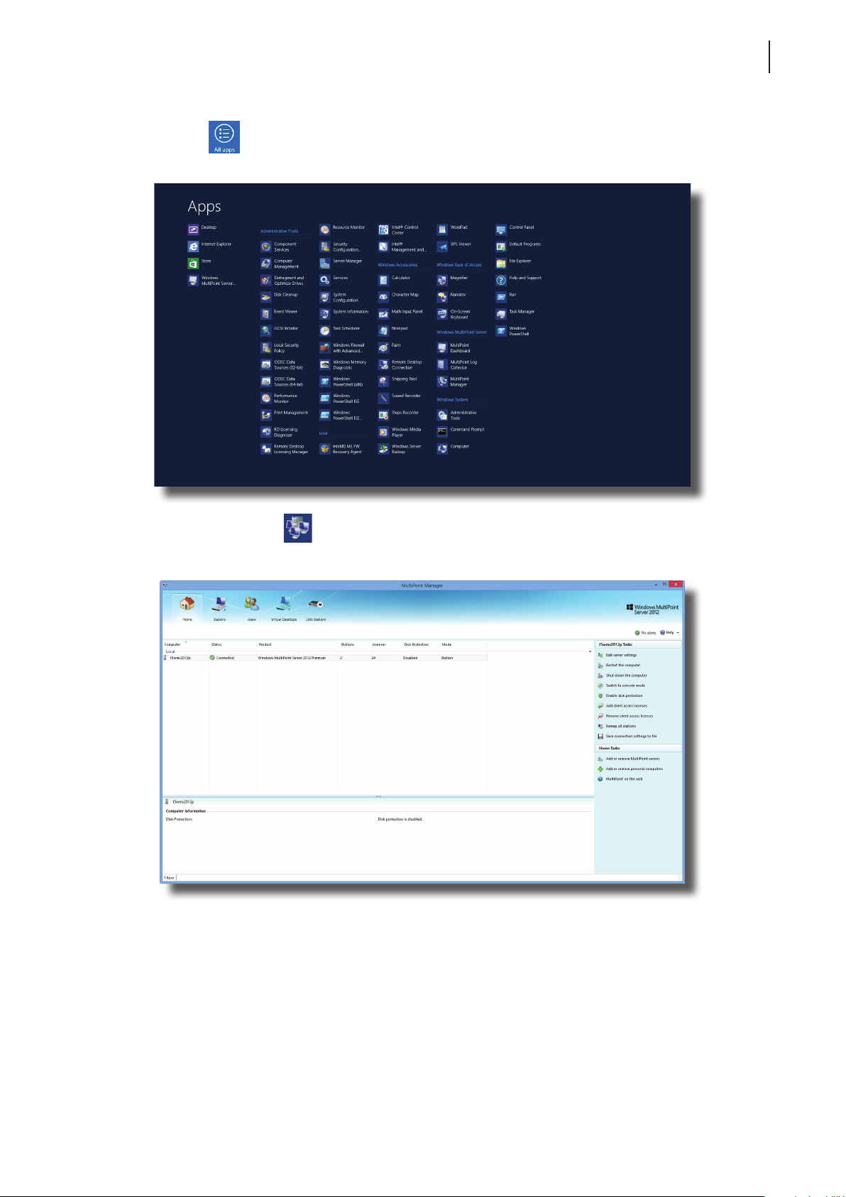
4. Click All apps
in the right-bottom corner to enter the screen with a list of all applications on your
host server.
5. Click MultiPoint Manager on the Apps list.
6. The MultiPoint Manager window appears.
7. Ensure that your system is in the Station rather than Console mode (click Switch to station mode on the
MultiPoint Manager window to switch to the Station mode if needed).
Page 30
Getting Your m320 Ready for Use
22
Initial Setup
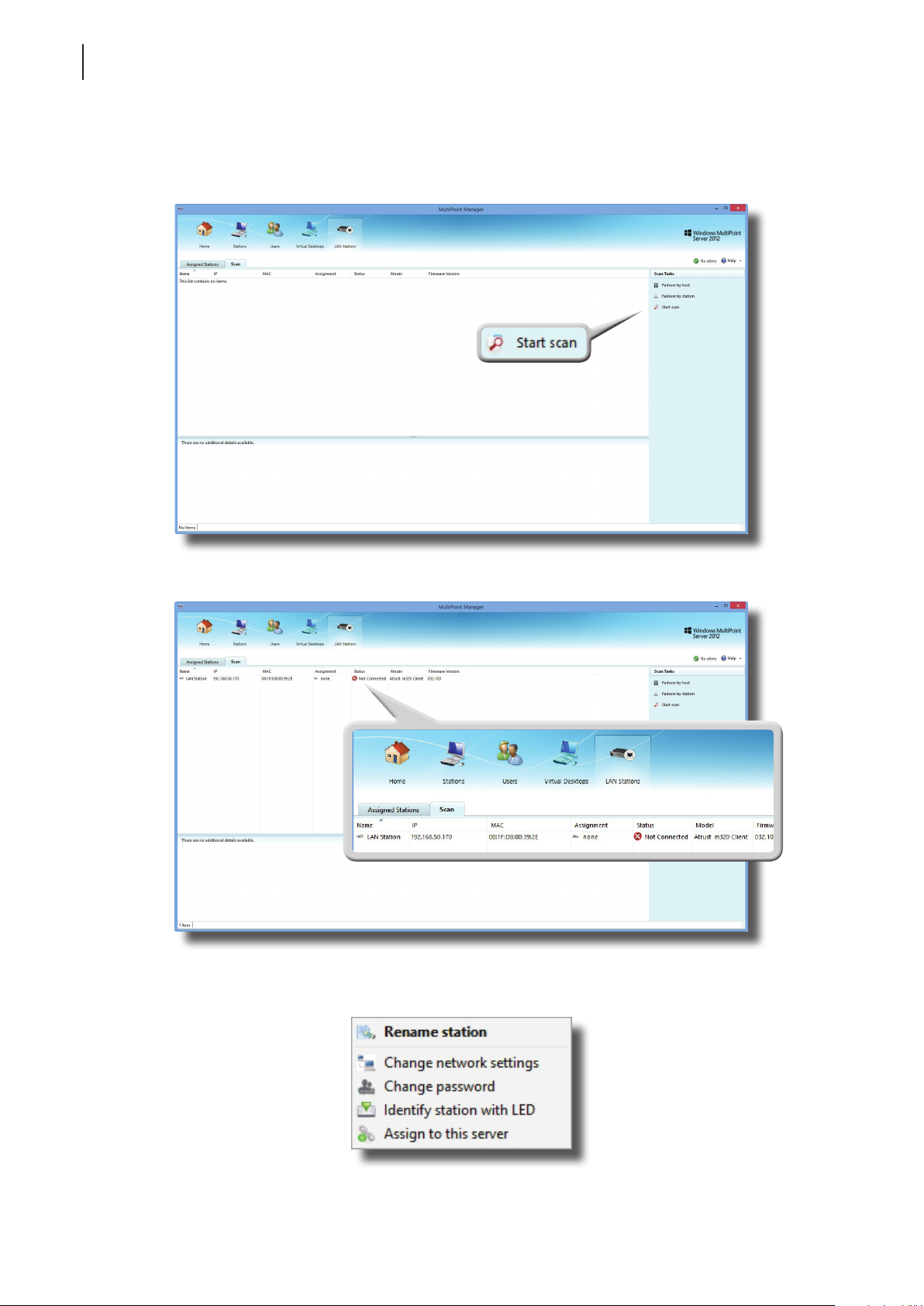
8. On LAN Stations tab, click Scan sub-tab, and then click Start scan.
LAN Stations Tab
9. All discovered LAN stations will be listed on the sub-tab.
10. Right-click on the desired LAN station to launch the popup menu, and then click Assign to this server.
Page 31
Getting Your m320 Ready for Use
NOTE
• For details on management features available for your m320, please refer to the
next chapter “Managing Your LAN Stations” on page 27.
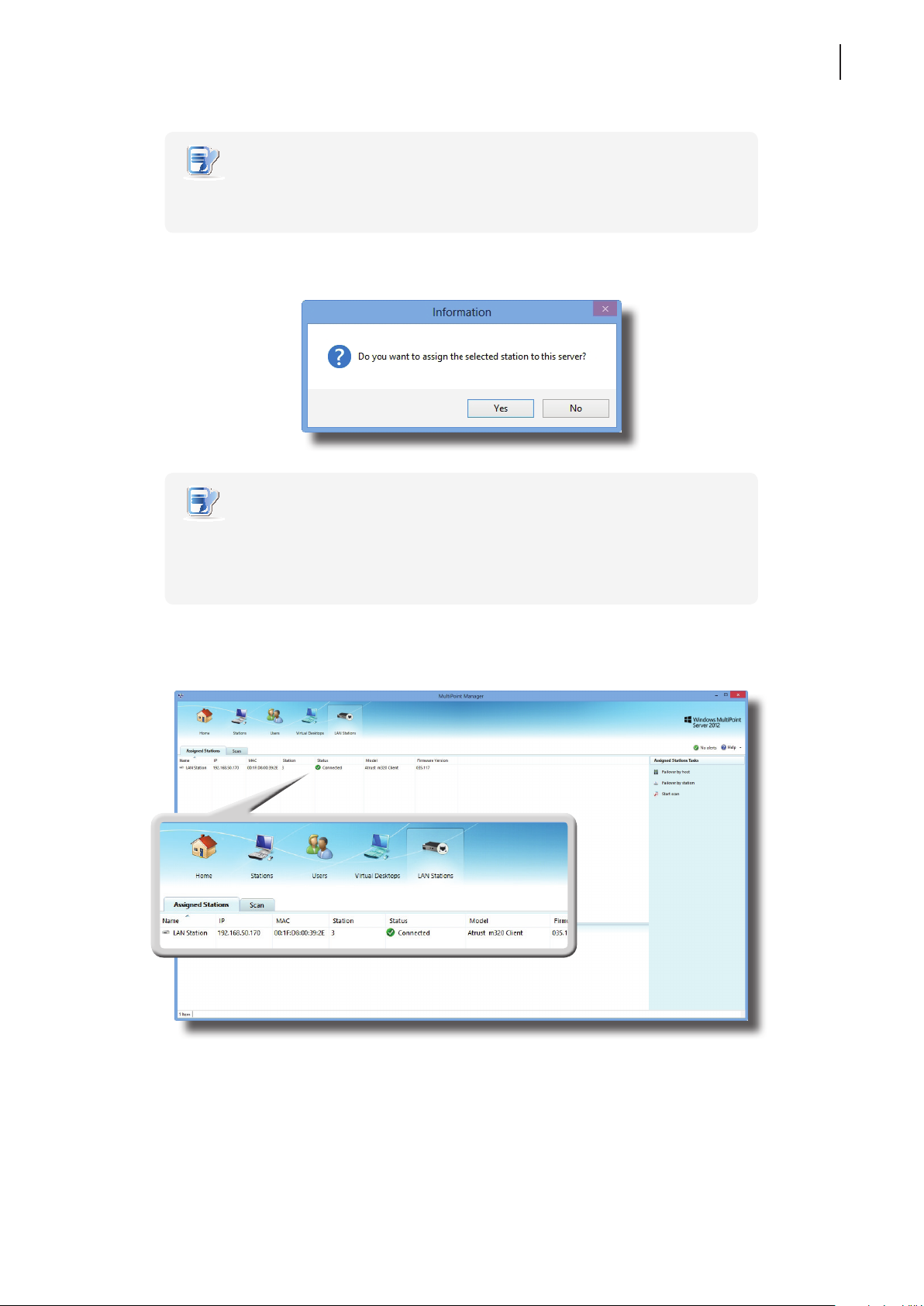
11. A window appears prompting for conrmation. Click Yes to conrm.
NOTE
• To assign multiple LAN stations to the host server, perform steps 10 through 11
for each station.
• If prompted, the default administrative password for LAN stations is admin.
23
Initial Setup
12. After completion, your LAN station is assigned to the desired host server and is moved from Scan to
Assigned Stations sub-tab.
Page 32
Getting Your m320 Ready for Use
24
Updating Drivers and the Utility
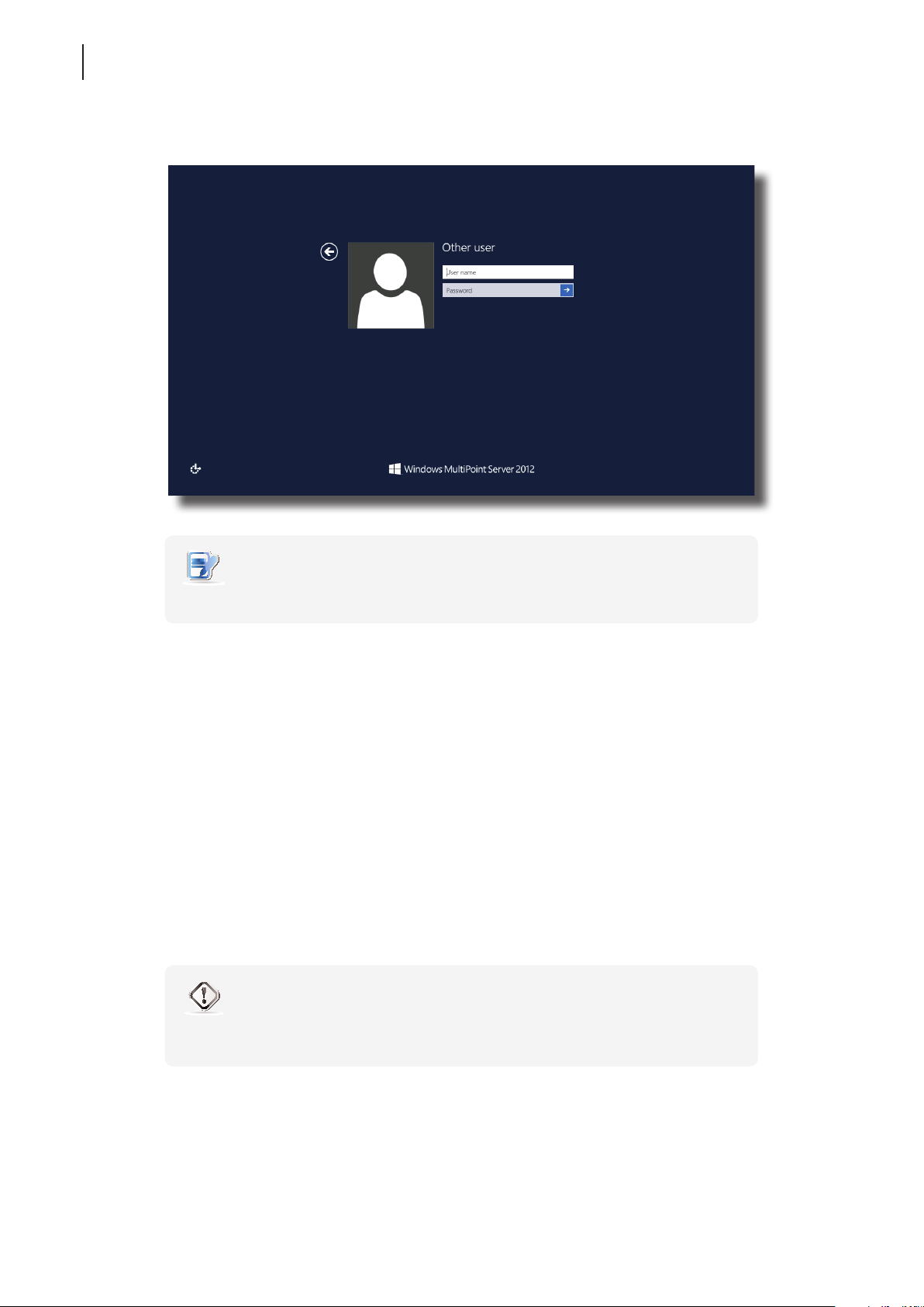
13. The Logon screen appears on the station.
NOTE
• You may need to wait a few seconds for this Logon screen to appear.
14. The bonding between your LAN station and its host server is established, and the m320-based LAN station is
now ready for use.
3.4 Updating Drivers and the Utility
Updating the Video Driver for your m320
To update the video driver for your m320-based LAN stations, please do the following:
1. On the primary station, log in to your MultiPoint Server system with an administrative account, and then
launch MultiPoint Manager.
2. On MultiPoint Manager, switch your system to the Console mode by clicking Switch to console mode.
3. A window appears prompting for conrmation. Ensure that you and other system users have saved their
work before clicking OK.
WARNING
• Switching the system mode will end all user sessions. Ensure all users have saved
their work to prevent data loss.
4. Switch o all your m320-based LAN stations.
5. Unplug all your m300 / m302-based USB stations if any.
Page 33
Getting Your m320 Ready for Use
Updating Drivers and the Utility
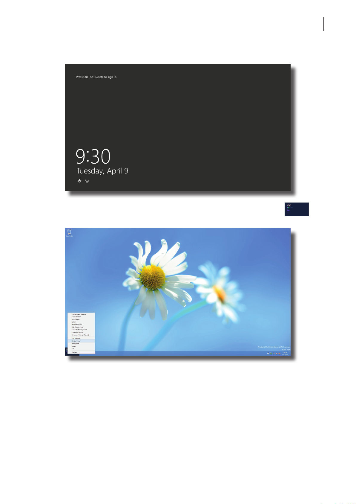
6. On the primary station, press Ctrl+Alt+Delete, and then log in with the same administrative account.
25
7. On the desktop, move mouse to the left-bottom corner, and then right-click on the appeared .
A popup menu appears.
8. Click to select Programs and Features on this popup menu.
9. On the Programs and Features window, click to select SMSC WMS FBR Graphics Software, and then
click Uninstall.
10. A window appears prompting for conrmation. Click Yes to conrm.
11. Restart your system to complete the uninstallation, and then switch to the Console mode again.
12. Install the new video driver, and then restart your system as required.
13. After the installation is completed, switch on or replug all your stations.
Page 34

Getting Your m320 Ready for Use
26
Updating Drivers and the Utility
Updating the LAN Station Driver and MultiPoint Manager Add-in
To update the LAN station driver and MultiPoint Manager Add-in for your m320-based LAN stations, please
do the following:
1. On the primary station, log in to your MultiPoint Server system with an administrative account, and then
launch MultiPoint Manager.
1. On LAN Stations tab, click Assigned Stations, and release all LAN stations from the host server by clicking
each station and Clear assignment. Click Yes to conrm when prompted.
2. On MultiPoint Manager, switch your system to the Console mode by clicking Switch to console mode.
3. A window appears prompting for conrmation. Ensure that you and other system users have saved their
work before clicking OK.
WARNING
• Switching the system mode will end all user sessions. Ensure all users have saved
their work to prevent data loss.
4. Switch o all your m320-based LAN stations.
5. On the primary station, press Ctrl+Alt+Delete, and then log in with the same administrative account.
6. On the desktop, move mouse to the left-bottom corner, and then right-click on the appeared [Start].
A popup menu appears.
7. Click to select Programs and Features on this popup menu.
8. On the Programs and Features window, click to select LAN Station Driver and Utility, and then
click Uninstall.
9. A window appears prompting for conrmation. Click Yes to continue.
10. A new window appears prompting for system restart. Restart your system as required to continue.
11. On the primary station, log in to your system with the same administrative account, and then click Desktop
on the Start screen.
12. The wizard starts uninstalling LAN Station Driver and Utility.
13. After completion, click Finish to exit the wizard, and then restart your system as required.
14. Switch to the Console mode again, and then install the new LAN station driver and utility.
15. After completion, click Finish to exit the wizard, and then restart your system as required.
16. Switch on all your m320-based LAN stations.
17. Re-assign each LAN station to the host server and allow rmware update when prompted.
Page 35

Managing Your LAN Stations
This chapter provides information on how to manage your m320-based LAN
stations with the MultiPoint Manager Add-in for LAN stations.
4.1 LAN Stations tab Overview
Overview of LAN Stations tab for managing LAN stations 29
4.2 Available Tasks at a Glance
Quick look at available tasks on LAN Stations tab 30
4.3 Taking Over a Failed Host
How to take over a failed host 31
4.4 Serving Orphaned LAN Stations
How to serve orphaned LAN stations 32
4
4.5 Scanning Free LAN Stations
How to nd free LAN stations over your local network 33
4.6 Renaming a LAN Station
How to rename a LAN station 33
4.7 Adjusting Network Settings for a LAN Station
How to adjust network settings for a LAN station 34
4.9 Identifying a LAN Station with its Power LED
How to identify a LAN station with its Power LED 36
4.10 Assigning a LAN Station to a Local Host Server
How to assign a LAN station to its host server 37
4.11 Clearing the Host Server Assignment for a LAN Station
How to release a LAN station from its host server 37
Page 36

Page 37
Managing Your LAN Stations
LAN Stations tab Overview
4.1 LAN Stations tab Overview
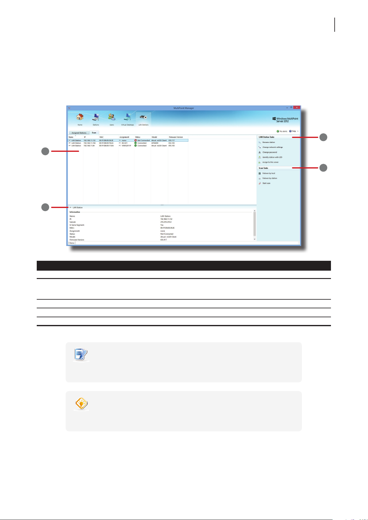
LAN Stations tab enables you to manage LAN based stations (Atrust m320 based). To access the content of LAN
Stations tab, click the tab on MultiPoint Manager.
Stations Tab Overview
1
29
3
4
2
Interface Elements
No. Name Description
1 Main Tab Content area
2 Additional Information area Displays the additional information for a selected LAN station.
3 Specic Task menu Displays the available tasks for a selected LAN station.
4 General Task menu Displays the available tasks for all LAN stations.
NOTE
• The available options on a Specic Task menu may vary, depending on the selected
item.
Displays information on LAN based stations over your local network.
Two sub-tabs are available: Assigned Stations and Scan. The former is for
managed stations; the latter is for free and manageable stations.
TIP
• You can right click on an item to open a context/popup/shortcut menu for quick
access to available tasks for the item.
Page 38
Managing Your LAN Stations
30
Available Tasks at a Glance
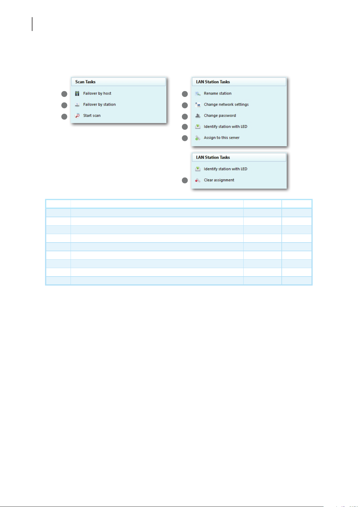
4.2 Available Tasks at a Glance
1
2
3
4
5
6
7
8
9
No. Available Task Section Page
1 select to take over a failed host 4.3 31
2 select to serve orphaned LAN stations 4.4 32
3 scan to nd free and manageable LAN stations 4.5 33
4 rename a free and manageable LAN station 4.6 33
5 assign an IP address for a LAN station 4.7 34
6 change the password for a LAN station 4.8 36
7 identify a LAN station with its Power LED 4.9 36
8 assign a LAN station to the local host server 4.10 37
9 clear the host server assignment for a LAN station 4.11 37
Page 39
Managing Your LAN Stations
Taking Over a Failed Host
4.3 Taking Over a Failed Host
You can designate a computer running Windows MultiPoint Server 2012 as a redundant host for another one. Once
the supported host fails, this redundant host will take over all its LAN stations.
NOTE
• Only LAN stations (m320-based) can be taken over by the redundant host;
USB stations (m300 / m302-based) cannot.
• You must install the drivers and utility of LAN stations for a redundant host.
For detailed instructions, please refer to section “3.2 Installing Drivers and the Utility”
on page 19.
• Once the supported host recovers, it will automatically take over all LAN stations
assigned to it. Users will be disconnected from their sessions if any on the
redundant host.
To designate a redundant host for another one, please do the following:
31
1. Log in to the planned redundant host with an administrative account, launch MultiPoint Manager, and then
click LAN Stations tab.
NOTE
• Ensure that the drivers and utility for LAN stations are installed on this redundant
host. Otherwise, LAN Stations tab won’t appear on MultiPoint Manager.
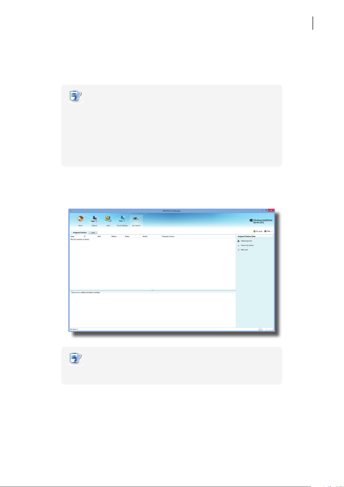
2. On LAN Stations tab, click Failover by host.
Page 40
Managing Your LAN Stations
32
Serving Orphaned LAN Stations
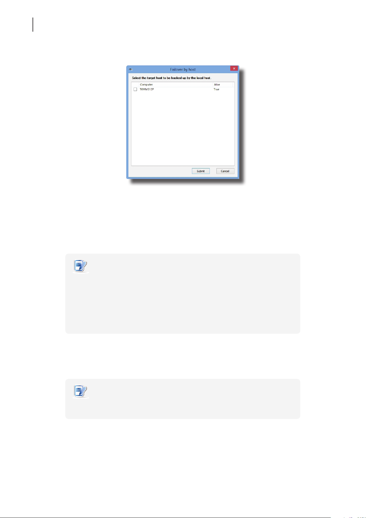
3. A window appears with a Target Host list.
4. Click to select the target host for this redundant host, and then click Submit to apply.
4.4 Serving Orphaned LAN Stations
You can designate a computer running Windows MultiPoint Server 2012 as a redundant host for m320-based
LAN stations. Once their host fails, this redundant host will take over all orphaned stations.
NOTE
• Only LAN stations (m320-based) can be taken over by the redundant host;
USB stations (m300 / m302-based) cannot.
• You must install the drivers and utility of LAN stations for a redundant host.
For detailed instructions, please refer to section “3.2 Installing Drivers and the Utility”
on page 19.
• Once their host recovers, LAN stations will be taken over again automatically.
Users will be disconnected from their sessions if any on the redundant host.
To designate a redundant host for LAN stations, please do the following:
1. Log in to the planned redundant host with an administrative account, launch MultiPoint Manager, and then
click LAN Stations tab.
NOTE
• Ensure that the drivers and utility for LAN stations are installed on this redundant
host. Otherwise, LAN Stations tab won’t appear on MultiPoint Manager.
2. On LAN Stations tab, click Failover by station.
Page 41
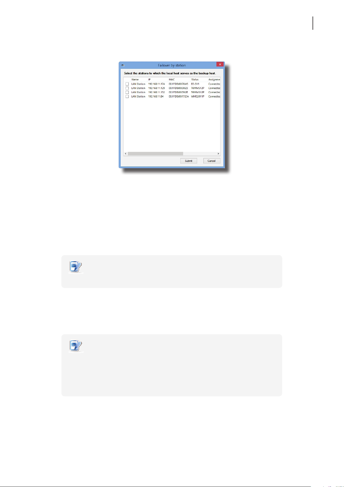
3. A window appears with a LAN Station list.
4. Click to select the desired LAN stations, and then click Submit to apply.
Managing Your LAN Stations
Scanning Free LAN Stations
33
4.5 Scanning Free LAN Stations
To nd free LAN stations over your local network, please do the following:
1. On LAN Stations tab, click Scan sub-tab, and then click Start scan.
2. All discovered LAN stations will be listed on the sub-tab.
NOTE
• Only manageable LAN stations (Atrust m320 based) will be listed.
4.6 Renaming a LAN Station
To rename a LAN station, please do the following:
NOTE
• You are not allowed to rename a managed LAN station (assigned to a MultiPoint®
Server system). Only a free LAN station can be renamed.
• To rename a managed LAN station, you need to release the station from its host
server rst. For instructions on how to release a LAN station, refer to section “4.11
Clearing the Host Server Assignment for a LAN Station” on page 37.
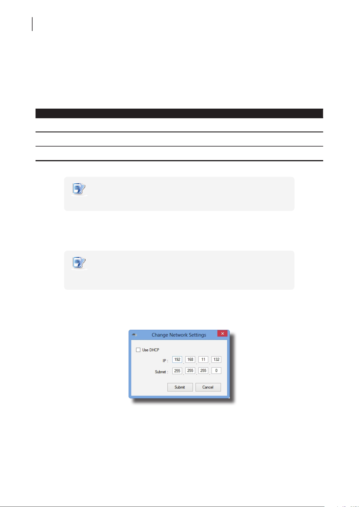
1. On LAN Stations tab, click Scan sub-tab, and then click to select the desired free LAN station.
2. Click Rename station. The Rename window then appears.
3. Type a new name, and then click Submit to apply.
Page 42
Managing Your LAN Stations
34
Adjusting Network Settings for a LAN Station
4.7 Adjusting Network Settings for a LAN Station
For your LAN station to be managed by a host server and ready for use, an IP address assigned to the station is
required. Normally, your Atrust m320 will perform network environment detection and choose an appropriate
IP address automatically. In case that you need to adjust the network conguration for your m320, refer to the
table below as guidelines on manual adjustment. Depending on dierent physical connections (see “2.2 Getting
Connected” on page 13), you need to select dierent methods to assign the IP address.
Two Methods for Assigning an IP Address to a LAN Station
Physical Connection
Method for LAN station
Method 1
Method 2
NOTE
• Only the network settings of a free LAN station can be adjusted.
connect m320 to your local network through
the same Gigabit switch as the host server
connect m320 to your local network
indirectly through the host server
Description IP Assignment Method
automatically assign an IP address by
the DHCP server over your local network
manually assign an IP address
Assigning an IP address automatically by the DHCP server
To assign an IP address automatically by the DHCP server for a LAN station, please do the following:
NOTE
• Ensure that your LAN station uses the method 1. See the description and related
section referred to at the beginning of this section.
1. On LAN Stations tab, click Scan sub-tab, and then click to select the desired free LAN station.
2. Click Change network settings. The Change Network Settings window appears.
3. Click to check Use DHCP, and then click Submit to apply.
Page 43
Managing Your LAN Stations
Adjusting Network Settings for a LAN Station
Assigning an IP Address Manually
To assign an IP address manually for a station, please do the following:
NOTE
• Ensure that your LAN station uses the method 2. See the description and related
section referred to at the beginning of this section.
1. On LAN Stations tab, click Scan sub-tab, and then click to select the desired free LAN station.
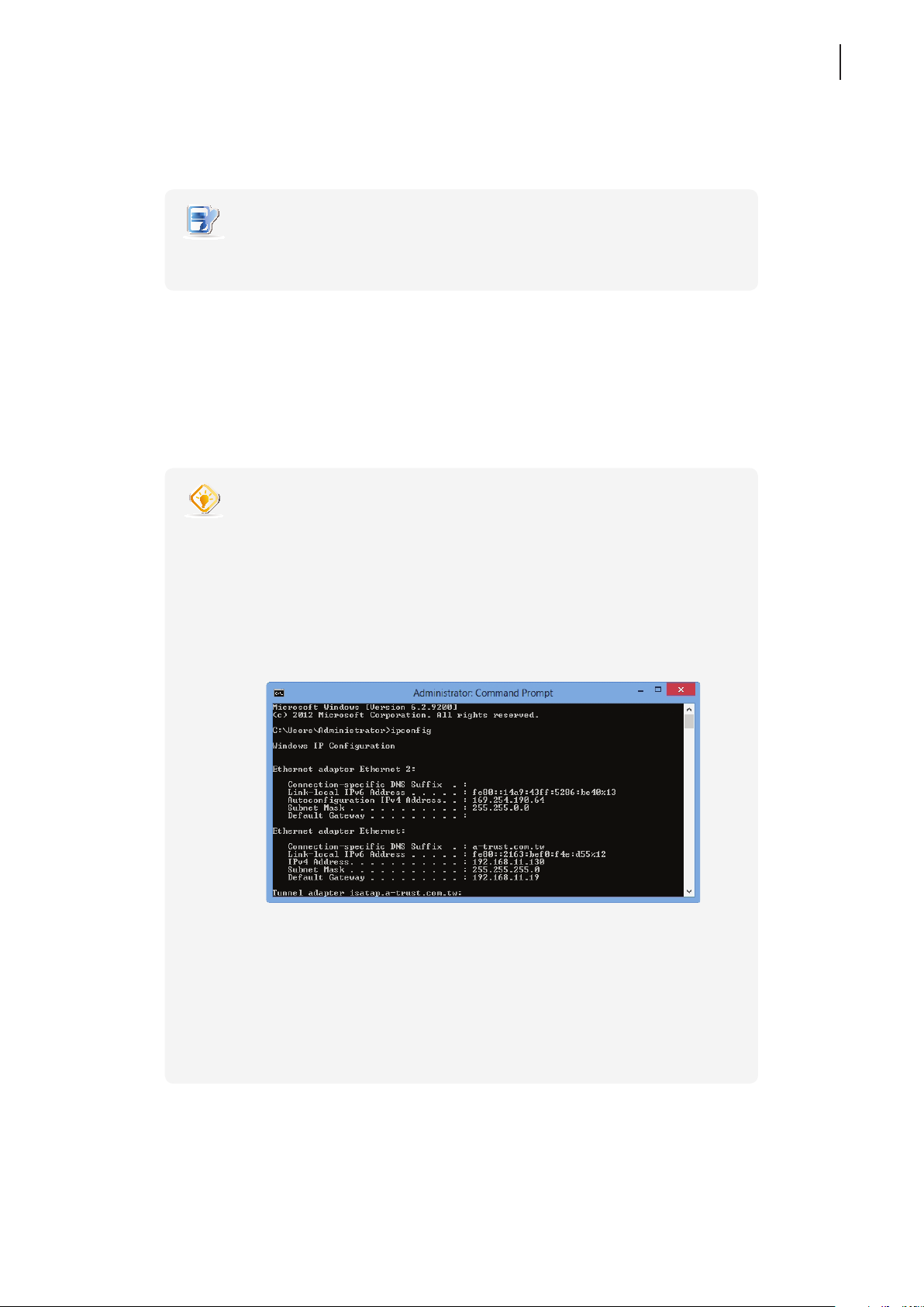
2. Click Change network settings. The Change Network Settings window appears.
3. Click to uncheck Use DHCP, and then type an appropriate IP address and subnet mask for the selected
LAN station.
4. Click Submit to apply.
TIP
• To nd out an appropriate IP address for a LAN station, please do the following:
1. On the host server side (the primary station), right-click on the Start screen.
A blue bar appears on the bottom of the screen.
2. Click All apps in the right-bottom corner to enter the screen with a list of all
applications on your host server, and then click Command Prompt.
3. The Command Prompt window appears.
4. Type ipcong, and then press Enter. The information about IP conguration is
shown in the window.
35
5. Under Ethernet adapter Ethernet or Ethernet adapter Ethernet 2, you can
nd the IP address w.x.y.z (Autoconguration IPv4 Address; e.g. 169.254.190.64,
in above case) and subnet mask information for the host server’s LAN port
which is used to connect a Gigabit switch and your LAN station (the other LAN
port is connected to your local network).
6. You could then assign your LAN stations an IP address in sequence,
for example, w.x.y.z+1, w.x.y.z+2, w.x.y.z+3, etc.
Page 44
Managing Your LAN Stations
36
Changing the Password for a LAN Station
4.8 Changing the Password for a LAN Station
To change the password for a LAN station, please do the following:
1. On LAN Stations tab, click Scan sub-tab, and then click the desired free LAN station.
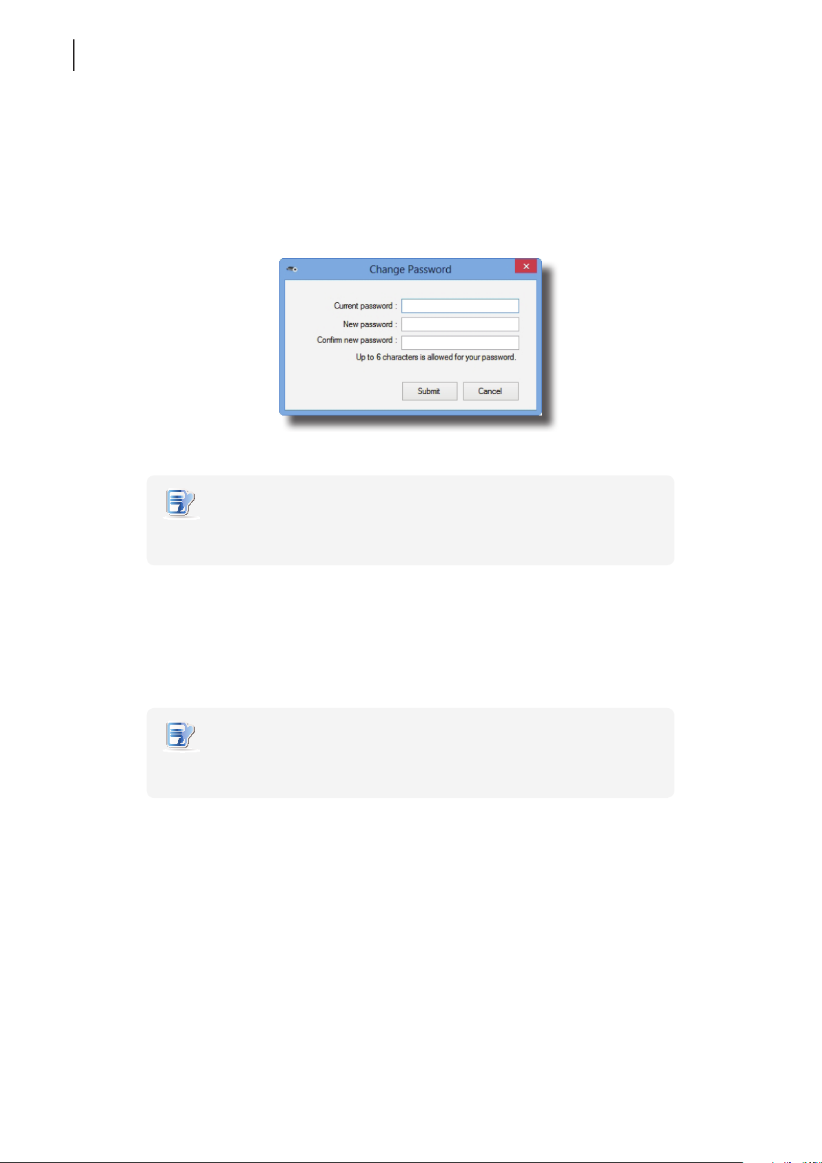
2. Click Change password. The Change Password window appears prompting you to type your current and
new passwords. The default is admin.
3. Type passwords and click Submit to apply.
NOTE
• You will need this password if you want to re-assign a LAN station which was
assigned to another host server but is not connected to that server now.
4.9 Identifying a LAN Station with its Power LED
To identify a LAN station with its Power LED, please do the following:
1. On LAN Stations tab, click Scan/Assigned Stations sub-tab, and then click to select the desired LAN station.
NOTE
• If your LAN station is managed by the server, you can nd it on Assigned Stations
sub-tab. Otherwise, you can nd your free LAN station on Scan sub-tab.
2. Click Identify station with LED. The power LED on the selected station is now ashing to help you identify
the station. The ashing will continue for 3 minutes.
Page 45
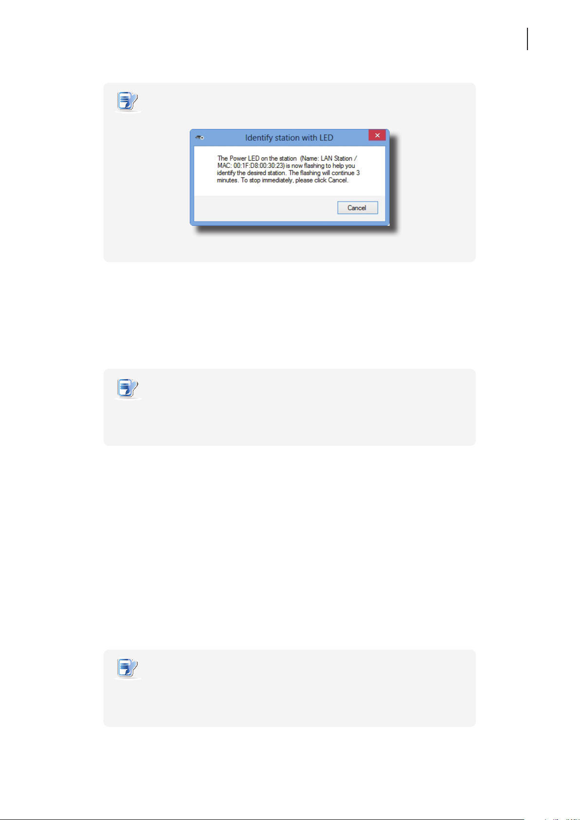
NOTE
• To stop ashing immediately, please click Cancel on the opened window:
3. Identify the desired station with its ashing Power LED.
Managing Your LAN Stations
Assigning a LAN Station to a Local Host Server
37
4.10 Assigning a LAN Station to a Local Host Server
To assign your LAN station to a local host server, please do the following:
NOTE
• You must log in to the desired host server with an administrative account to assign
your LAN station to that server; you are not allowed to assign a LAN station to a
remotely managed server.
1. On LAN Stations tab, click Scan sub-tab, and then click the desired free LAN station.
2. Click Assign to this server.
3. When it’s done, your station is assigned to the server and is moved from Scan to Assigned Stations sub-tab.
4. The station is now managed by this host server and is ready for use.
4.11 Clearing the Host Server Assignment for a LAN Station
To clear the host server assignment for a LAN station, please do the following:
1. On LAN Stations tab, click Assigned Stations sub-tab, and then click the desired LAN station.
2. Click Clear assignment.
NOTE
• If you clear the host server assignment for a LAN station which is originally managed
by another host server, you may be prompted to provide the password. The default
password is admin if you didn’t change the default.
Page 46

Managing Your LAN Stations
38
Clearing the Host Server Assignment for a LAN Station
3. A window appears prompting you for conrmation. Click OK to continue.
4. When it’s done, your station is released from the server and moved from Assigned Stations to Scan sub-tab.
5. The station is now free and manageable by another host server.
Page 47

Specications
Specications
Atrust m320 zero client
Connection type
License
Compatible server OS
Resolutions
I/O interfaces
Security
Power
Mount
Dimensions
Weight
Environment
1 Your deal may not contain this OEM Windows MultiPoint Server 2012 CAL. To obtain a license, please refer to Microsoft web pages at http://www.microsoft.com/windows/multipoint/buy.aspx
or http://www.microsoft.com/windows/multipoint/default.aspx.
Gigabit Ethernet (RJ-45)
Windows® MultiPoint® Server 2012 Client Access License (CAL)
Windows® MultiPoint® Server 2012
Up to 1920 x 1080
Front Panel:
2 x USB (A type, for extra USB devices)
1 x headphone
1 x microphone
1 x Kensington lock slot
INPUT: 100-240Vac, 50-60Hz, 300mA
OUTPUT: +5Vdc, 2A MAX
VESA mount kit, (W) 114 x (H) 6 x (D) 60 mm (optional)
(W) 120 x (H) 28 x (D) 80 mm
128 g (approx.), excluding AC adaptor
Operating Temperature: 0° C ~ 35° C
Opearting Humidity (Rh): 10% ~ 90% (non-condensing)
Non-operating Humidity (Rh): 5% ~ 95%
Rear Panel:
1 x RJ-45 (Gigabit Ethernet, for connecting to host)
2 x USB (A type, only for keyboard/mouse)
1 x VGA
1 x DC IN
1
39
Page 48

40
Page 49

UM-m320-WMS12-EN-14012810
Page 50

 Loading...