

Page 1

The Atmel-ICE Debugger
Programmers and Debuggers
Atmel-ICE
USER GUIDE
Atmel-ICE is a powerful development tool for debugging and programming
ARM® Cortex®-M based Atmel® SAM and Atmel AVR® microcontrollers with
On-Chip Debug capability.
It supports:
• Programming and on-chip debugging of all Atmel AVR 32-bit
microcontrollers on both JTAG and aWire interfaces
• Programming and on-chip debugging of all Atmel AVR XMEGA® family
devices on both JTAG and PDI 2-wire interfaces
• Programming (JTAG, SPI, UPDI) and debugging of all Atmel AVR 8-bit
microcontrollers with OCD support on either JTAG, debugWIRE or
UPDI interfaces
• Programming and debugging of all Atmel SAM ARM Cortex-M based
microcontrollers on both SWD and JTAG interfaces
• Programming (TPI) of all Atmel tinyAVR® 8-bit microcontrollers with
support for this interface
Consult the supported devices list in the Atmel Studio User Guide for a full
list of devices and interfaces supported by this firmware release.
Atmel-42330C-Atmel-ICE_User Guide-10/2016
Page 2

Table of Contents
The Atmel-ICE Debugger................................................................................................ 1
1. Introduction................................................................................................................5
1.1. Introduction to the Atmel-ICE....................................................................................................... 5
1.2. Atmel-ICE Features......................................................................................................................5
1.3. System Requirements.................................................................................................................. 6
2. Getting Started with the Atmel-ICE............................................................................7
2.1. Full Kit Contents........................................................................................................................... 7
2.2. Basic Kit Contents........................................................................................................................ 7
2.3. PCBA Kit Contents....................................................................................................................... 8
2.4. Spare Parts Kits............................................................................................................................8
2.5. Kit Overview................................................................................................................................. 9
2.6. Assembling the Atmel-ICE..........................................................................................................10
2.7. Opening the Atmel-ICE...............................................................................................................11
2.8. Powering the Atmel-ICE............................................................................................................. 13
2.9. Connecting to the Host Computer.............................................................................................. 13
2.10. USB Driver Installation............................................................................................................... 13
2.10.1. Windows...................................................................................................................... 13
3. Connecting the Atmel-ICE....................................................................................... 15
3.1. Connecting to AVR and SAM Target Devices.............................................................................15
3.2. Connecting to a JTAG Target..................................................................................................... 16
3.3. Connecting to an aWire Target...................................................................................................17
3.4. Connecting to a PDI Target........................................................................................................ 18
3.5. Connecting to a UPDI Target......................................................................................................18
3.6. Connecting to a debugWIRE Target...........................................................................................19
3.7. Connecting to an SPI Target...................................................................................................... 20
3.8. Connecting to a TPI Target.........................................................................................................21
3.9. Connecting to an SWD Target....................................................................................................22
3.10. Connecting to Data Gateway Interface...................................................................................... 23
4. On-chip Debugging..................................................................................................24
4.1. Introduction.................................................................................................................................24
4.2. SAM Devices with JTAG/SWD...................................................................................................24
4.2.1. ARM CoreSight Components...................................................................................... 24
4.2.2. JTAG Physical Interface...............................................................................................25
4.2.3. Connecting to a JTAG Target.......................................................................................27
4.2.4. SWD Physical Interface............................................................................................... 28
4.2.5. Connecting to an SWD Target..................................................................................... 28
4.2.6. Special Considerations................................................................................................ 29
4.3. AVR UC3 Devices with JTAG/aWire...........................................................................................29
4.3.1. Atmel AVR UC3 On-chip Debug System.....................................................................30
4.3.2. JTAG Physical Interface...............................................................................................30
4.3.3. Connecting to a JTAG Target.......................................................................................32
Atmel Atmel-ICE [USER GUIDE]
Atmel-42330C-Atmel-ICE_User Guide-10/2016
2
Page 3

4.3.4. aWire Physical Interface.............................................................................................. 33
4.3.5. Connecting to an aWire Target.................................................................................... 34
4.3.6. Special Considerations................................................................................................ 35
4.3.7. EVTI / EVTO Usage.....................................................................................................35
4.4. tinyAVR, megaAVR, and XMEGA Devices.................................................................................35
4.4.1. JTAG Physical Interface...............................................................................................36
4.4.2. Connecting to a JTAG Target.......................................................................................36
4.4.3. SPI Physical Interface..................................................................................................38
4.4.4. Connecting to an SPI Target........................................................................................38
4.4.5. PDI...............................................................................................................................39
4.4.6. Connecting to a PDI Target..........................................................................................39
4.4.7. UPDI Physical Interface...............................................................................................40
4.4.8. Connecting to a UPDI Target.......................................................................................41
4.4.9. TPI Physical Interface..................................................................................................42
4.4.10. Connecting to a TPI Target..........................................................................................42
4.4.11. Advanced Debugging (AVR JTAG /debugWIRE devices)........................................... 43
4.4.12. megaAVR Special Considerations...............................................................................44
4.4.13. AVR XMEGA Special Considerations..........................................................................45
4.4.14. debugWIRE Special Considerations............................................................................46
4.4.15. debugWIRE Software Breakpoints.............................................................................. 47
4.4.16. Understanding debugWIRE and the DWEN Fuse....................................................... 47
4.4.17. TinyX-OCD (UPDI) Special Considerations.................................................................48
5. Hardware Description.............................................................................................. 50
5.1. LEDs...........................................................................................................................................50
5.2. Rear Panel..................................................................................................................................50
5.3. Bottom Panel..............................................................................................................................51
5.4. Architecture Description............................................................................................................. 51
5.4.1. Atmel-ICE Main Board................................................................................................. 51
5.4.2. Atmel-ICE Target Connectors...................................................................................... 52
5.4.3. Atmel-ICE Target Connectors Part Numbers...............................................................52
6. Software Integration.................................................................................................53
6.1. Atmel Studio............................................................................................................................... 53
6.1.1. Software Integration in Atmel Studio........................................................................... 53
6.1.2. Programming Options..................................................................................................53
6.1.3. Debug Options.............................................................................................................53
6.2. Command Line Utility................................................................................................................. 54
7. Advanced Debugging Techniques........................................................................... 55
7.1. Atmel AVR UC3 Targets............................................................................................................. 55
7.1.1. EVTI / EVTO Usage.....................................................................................................55
7.2. debugWIRE Targets................................................................................................................... 55
7.2.1. debugWIRE Software Breakpoints.............................................................................. 55
8. Release History and Known issues......................................................................... 57
8.1. Firmware Release History.......................................................................................................... 57
8.2. Known Issues Concerning the Atmel-ICE.................................................................................. 57
8.2.1. General........................................................................................................................ 57
Atmel Atmel-ICE [USER GUIDE]
Atmel-42330C-Atmel-ICE_User Guide-10/2016
3
Page 4

8.2.2. Atmel AVR XMEGA OCD Specific Issues....................................................................57
8.2.3. Atmel AVR - Device Specific Issues............................................................................ 58
9. Product Compliance................................................................................................ 59
9.1. RoHS and WEEE....................................................................................................................... 59
9.2. CE and FCC............................................................................................................................... 59
10. Revision History.......................................................................................................60
Atmel Atmel-ICE [USER GUIDE]
Atmel-42330C-Atmel-ICE_User Guide-10/2016
4
Page 5

1. Introduction
1.1. Introduction to the Atmel-ICE
Atmel-ICE is a powerful development tool for debugging and programming ARM Cortex-M based Atmel
SAM and Atmel AVR microcontrollers with On-Chip Debug capability.
It supports:
• Programming and on-chip debugging of all Atmel AVR UC3 microcontrollers on both JTAG and
aWire interfaces
• Programming and on-chip debugging of all AVR XMEGA family devices on both JTAG and PDI 2-
wire interfaces
• Programming (JTAG and SPI) and debugging of all AVR 8-bit microcontrollers with OCD support on
both JTAG or debugWIRE interfaces
• Programming and debugging of all Atmel SAM ARM Cortex-M based microcontrollers on both SWD
and JTAG interfaces
• Programming (TPI) of all Atmel tinyAVR 8-bit microcontrollers with support for this interface
1.2. Atmel-ICE Features
• Fully compatible with Atmel Studio
• Supports programming and debugging of all Atmel AVR UC3 32-bit microcontrollers
• Supports programming and debugging of all 8-bit AVR XMEGA devices
• Supports programming and debugging of all 8-bit Atmel megaAVR® and tinyAVR devices with OCD
• Supports programming and debugging of all SAM ARM Cortex-M based microcontrollers
• Target operating voltage range of 1.62V to 5.5V
• Draws less than 3mA from target VTref when using debugWIRE interface and less than 1mA for all
other interfaces
• Supports JTAG clock frequencies from 32kHz to 7.5MHz
• Supports PDI clock frequencies from 32kHz to 7.5MHz
• Supports debugWIRE baud rates from 4kbit/s to 0.5Mbit/s
• Supports aWire baud rates from 7.5kbit/s to 7Mbit/s
• Supports SPI clock frequencies from 8kHz to 5MHz
• Supports UPDI baud rates from up to 750kbit/s
• Supports SWD clock frequencies from 32kHz to 10MHz
• USB 2.0 high-speed host interface
• ITM serial trace capture at up to 3MB/s
• Supports DGI SPI and USART interfaces when not debugging or programming
• Supports 10-pin 50-mil JTAG connector with both AVR and Cortex pinouts. The standard probe
cable supports AVR 6-pin ISP/PDI/TPI 100-mil headers as well as 10-pin 50-mil. An adapter is
available to support 6-pin 50-mil, 10-pin 100-mil, and 20-pin 100-mil headers. Several kit options
are available with different cabling and adapters.
Atmel Atmel-ICE [USER GUIDE]
Atmel-42330C-Atmel-ICE_User Guide-10/2016
5
Page 6

1.3. System Requirements
The Atmel-ICE unit requires that a front-end debugging environment Atmel Studio version 6.2 or later is
installed on your computer.
The Atmel-ICE should be connected to the host computer using the USB cable provided, or a certified
Micro-USB cable.
Atmel Atmel-ICE [USER GUIDE]
Atmel-42330C-Atmel-ICE_User Guide-10/2016
6
Page 7
2. Getting Started with the Atmel-ICE
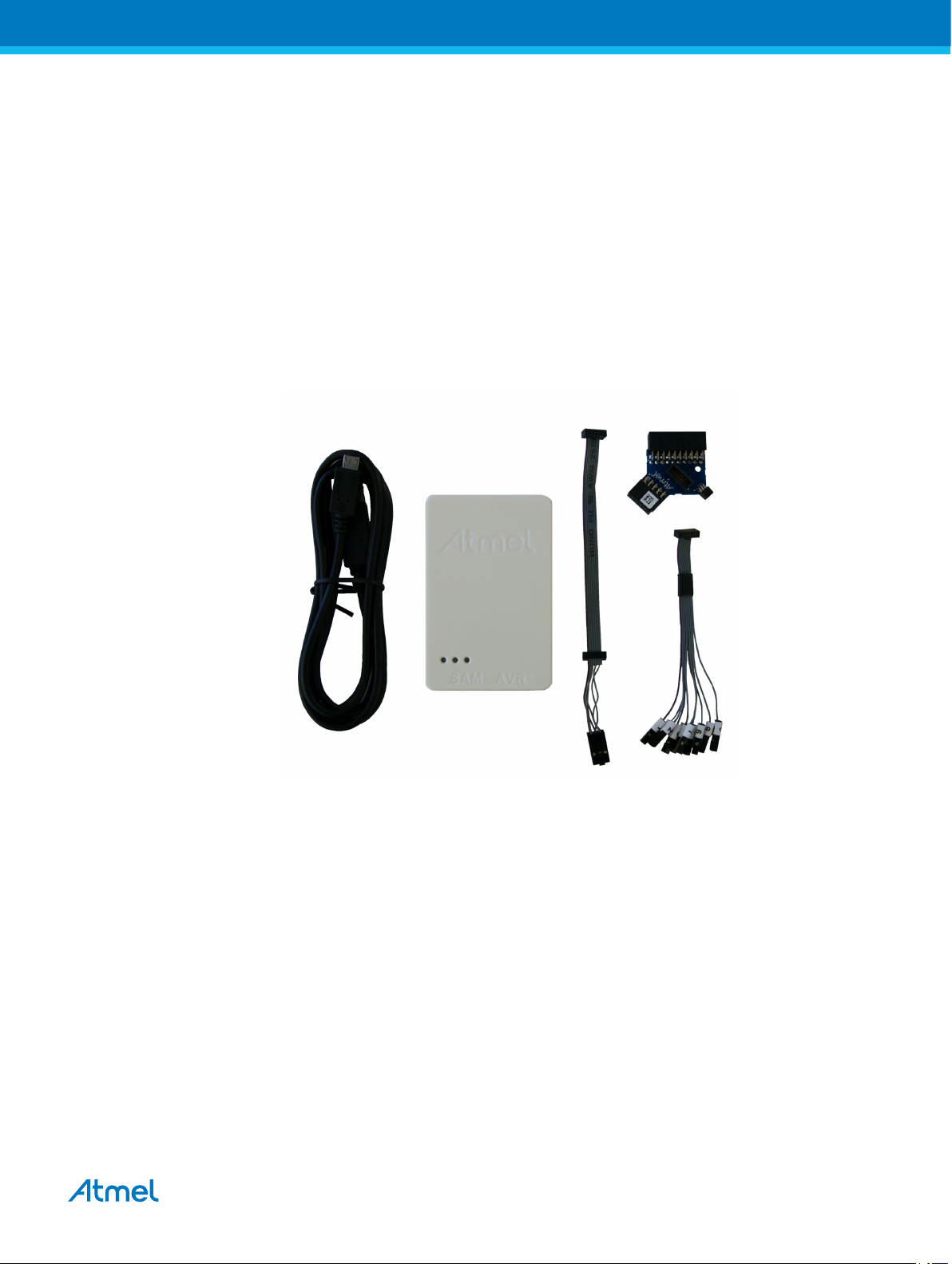
2.1. Full Kit Contents
The Atmel-ICE full kit contains these items:
• Atmel-ICE unit
• USB cable (1.8m, high-speed, Micro-B)
• Adapter board containing 50-mil AVR, 100-mil AVR/SAM, and 100-mil 20-pin SAM adapters
• IDC flat cable with 10-pin 50-mil connector and 6-pin 100-mil connector
• 50-mil 10-pin mini squid cable with 10 x 100-mil sockets
Figure 2-1. Atmel-ICE Full Kit Contents
2.2. Basic Kit Contents
The Atmel-ICE basic kit contains these items:
• Atmel-ICE unit
• USB cable (1.8m, high-speed, Micro-B)
• IDC flat cable with 10-pin 50-mil connector and 6-pin 100-mil connector
Atmel Atmel-ICE [USER GUIDE]
Atmel-42330C-Atmel-ICE_User Guide-10/2016
7
Page 8
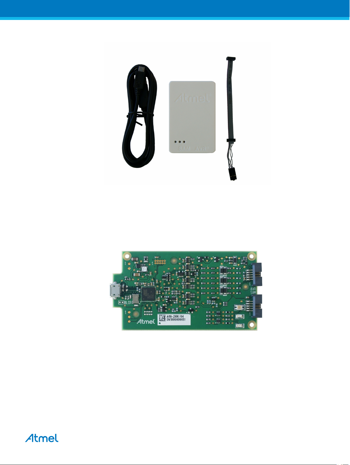
Figure 2-2. Atmel-ICE Basic Kit Contents
2.3. PCBA Kit Contents
The Atmel-ICE PCBA kit contains these items:
• Atmel-ICE unit without plastic encapsulation
Figure 2-3. Atmel-ICE PCBA Kit Contents
2.4. Spare Parts Kits
The following spare parts kits are available:
• Adapter kit
• Cable kit
Atmel Atmel-ICE [USER GUIDE]
Atmel-42330C-Atmel-ICE_User Guide-10/2016
8
Page 9

Figure 2-4. Atmel-ICE Adapter Kit Contents
Figure 2-5. Atmel-ICE Cable Kit Contents
2.5. Kit Overview
The Atmel-ICE kit options are shown diagrammatically here:
Figure 2-6. Atmel-ICE Kit Overview
PCBA kit
PCBA
full kit
basic kit
adapter kit
cable kit
SAM AVR
Atmel Atmel-ICE [USER GUIDE]
Atmel-42330C-Atmel-ICE_User Guide-10/2016
9
Page 10

2.6. Assembling the Atmel-ICE
The Atmel-ICE unit is shipped with no cables attached. Two cable options are provided in the full kit:
• 50-mil 10-pin IDC flat cable with 6-pin ISP and 10-pin connectors
• 50-mil 10-pin mini-squid cable with 10 x 100-mil sockets
Figure 2-7. Atmel-ICE Cables
For most purposes, the 50-mil 10-pin IDC flat cable can be used, connecting either natively to its 10-pin
or 6-pin connectors, or connecting via the adapter board. Three adapters are provided on one small
PCBA. The following adapters are included:
• 100-mil 10-pin JTAG/SWD adapter
• 100-mil 20-pin SAM JTAG/SWD adapter
• 50-mil 6-pin SPI/debugWIRE/PDI/aWire adapter
Figure 2-8. Atmel-ICE Adapters
Note:
A 50-mil JTAG adapter has not been provided - this is because the 50-mil 10-pin IDC cable can be used
to connect directly to a 50-mil JTAG header. For the part number of the component used for the 50-mil
10-pin connector, see Atmel-ICE Target Connectors Part Numbers.
The 6-pin ISP/PDI header is included as part of the 10-pin IDC cable. This termination can be cut off if it
is not required.
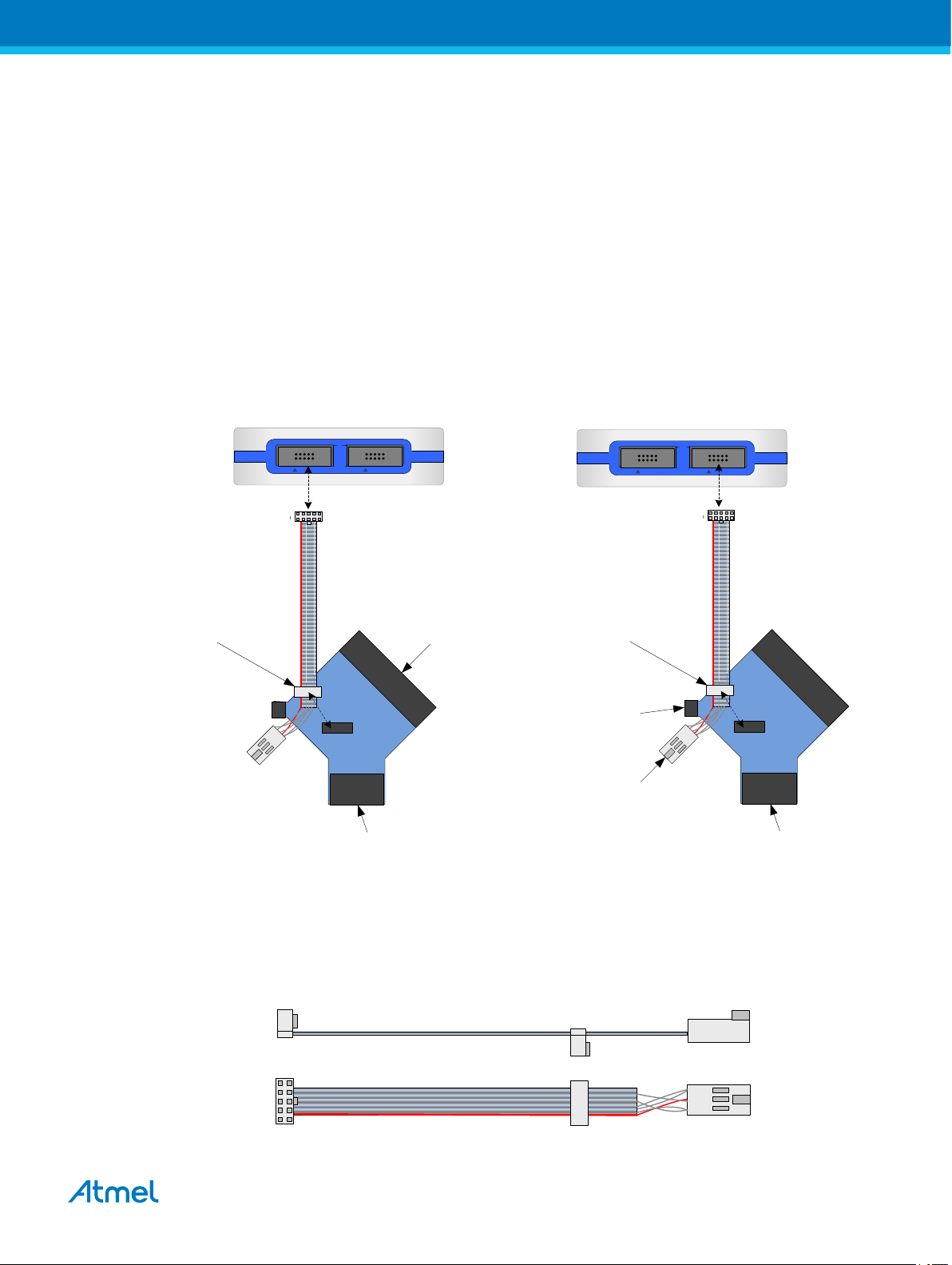
To assemble your Atmel-ICE into its default configuration, connect the 10-pin 50-mil IDC cable to the unit
as shown below. Be sure to orient the cable so that the red wire (pin 1) on the cable aligns with the
triangular indicator on the blue belt of the enclosure. The cable should connect upwards from the unit. Be
sure to connect to the port corresponding to the pinout of your target - AVR or SAM.
Atmel Atmel-ICE [USER GUIDE]
Atmel-42330C-Atmel-ICE_User Guide-10/2016
10
Page 11
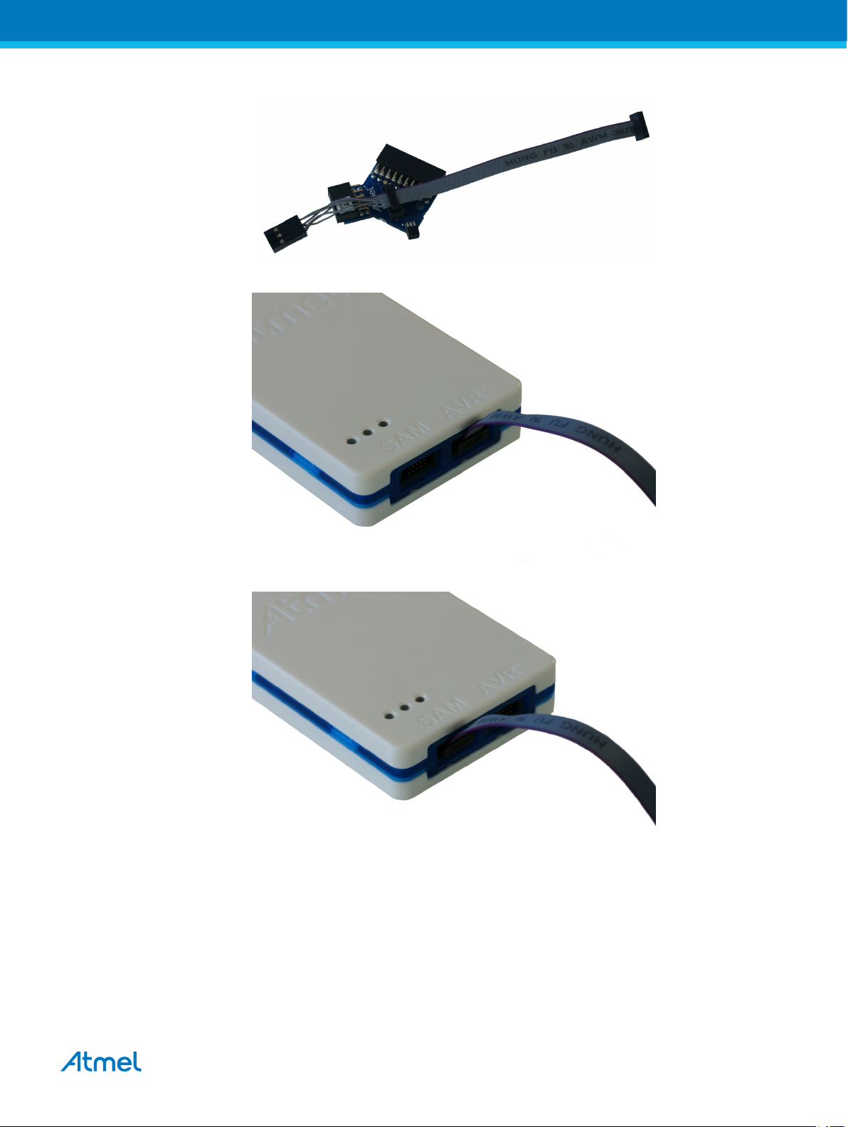
Figure 2-9. Atmel-ICE Cable Connection
Figure 2-10. Atmel-ICE AVR Probe Connection
Figure 2-11. Atmel-ICE SAM Probe Connection
2.7. Opening the Atmel-ICE
Note:
For normal operation, the Atmel-ICE unit must not be opened. Opening the unit is done at your own risk.
Anti-static precautions should be taken.
The Atmel-ICE enclosure consists of three separate plastic components - top cover, bottom cover, and
blue belt - which are snapped together during assembly. To open the unit, simply insert a large flat
Atmel Atmel-ICE [USER GUIDE]
Atmel-42330C-Atmel-ICE_User Guide-10/2016
11
Page 12
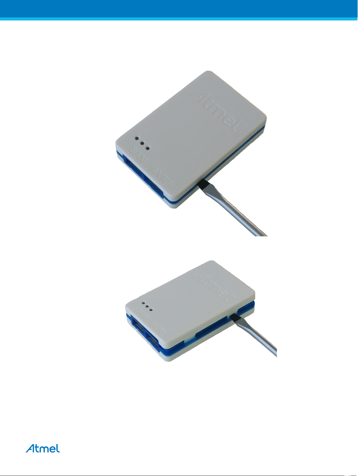
screwdriver into the openings in the blue belt, apply some inward pressure and twist gently. Repeat the
process on the other snapper holes, and the top cover will pop off.
Figure 2-12. Opening the Atmel-ICE (1)
Figure 2-13. Opening the Atmel-ICE (2)
Atmel Atmel-ICE [USER GUIDE]
Atmel-42330C-Atmel-ICE_User Guide-10/2016
12
Page 13
Figure 2-14. Opening the Atmel-ICE(3)
To close the unit again, simply align the top and bottom covers correctly, and press firmly together.
2.8. Powering the Atmel-ICE
The Atmel-ICE is powered by the USB bus voltage. It requires less than 100mA to operate, and can
therefore be powered through a USB hub. The power LED will illuminate when the unit is plugged in.
When not connected in an active programming or debugging session, the unit will enter low-power
consumption mode to preserve your computer's battery. The Atmel-ICE cannot be powered down - it
should be unplugged when not in use.
2.9. Connecting to the Host Computer
The Atmel-ICE communicates primarily using a standard HID interface, and does not require a special
driver on the host computer. To use the advanced Data Gateway functionality of the Atmel-ICE, be sure to
install the USB driver on the host computer. This is done automatically when installing the front-end
software provided free by Atmel. See www.atmel.com for further information or to download the latest
front-end software.
The Atmel-ICE must be connected to an available USB port on the host computer using the USB cable
provided, or suitable USB certified micro cable. The Atmel-ICE contains a USB 2.0 compliant controller,
and can operate in both full-speed and high-speed modes. For best results, connect the Atmel-ICE
directly to a USB 2.0 compliant high-speed hub on the host computer using the cable provided.
2.10. USB Driver Installation
2.10.1. Windows
When installing the Atmel-ICE on a computer running Microsoft® Windows®, the USB driver is loaded
when the Atmel-ICE is first plugged in.
Note:
Be sure to install the front-end software packages before plugging the unit in for the first time.
Atmel Atmel-ICE [USER GUIDE]
Atmel-42330C-Atmel-ICE_User Guide-10/2016
13
Page 14

Once successfully installed, the Atmel-ICE will appear in the device manager as a "Human Interface
Device".
Atmel Atmel-ICE [USER GUIDE]
Atmel-42330C-Atmel-ICE_User Guide-10/2016
14
Page 15
3. Connecting the Atmel-ICE
A B
1 2
9
1 2
9 10
1
1
2
5
10
3.1. Connecting to AVR and SAM Target Devices
The Atmel-ICE is equipped with two 50-mil 10-pin JTAG connectors. Both connectors are directly
electrically connected, but conform to two different pinouts; the AVR JTAG header and the ARM Cortex
Debug header. The connector should be selected based on the pinout of the target board, and not the
target MCU type - for example a SAM device mounted in an AVR STK®600 stack should use the AVR
header.
Various cabling and adapters are available in the different Atmel-ICE kits. An overview of connection
options is shown.
Figure 3-1. Atmel-ICE Connection Options
10-pin 50-mil JTAG/SWD
(Cortex debug header)
SAM AVR
20-pin 100-mil SAM
header
(for EVKs etc)
6-pin 50-mil AVR ISP/
debugWIRE/PDI/aWire/
TPI header
10-pin 100-mil
JTAG/SWD header
SAM AVR
10-pin 50-mil AVR
JTAG header
6-pin 100-mil AVR ISP/
debugWIRE/PDI/aWire/
TPI header
10-pin 100-mil AVR
JTAG header
The red wire marks pin 1 of the 10-pin 50-mil connector. Pin 1 of the 6-pin 100-mil connector is placed to
the right of the keying when the connector is seen from the cable. Pin 1 of each connector on the adapter
is marked with a white dot. The figure below shows the pinout of the debug cable. The connector marked
A plugs into the debugger while the B side plugs into the target board.
Figure 3-2. Debug Cable Pinout
Atmel Atmel-ICE [USER GUIDE]
Atmel-42330C-Atmel-ICE_User Guide-10/2016
15
Page 16
3.2. Connecting to a JTAG Target
The Atmel-ICE is equipped with two 50-mil 10-pin JTAG connectors. Both connectors are directly
electrically connected, but conform to two different pinouts; the AVR JTAG header and the ARM Cortex
Debug header. The connector should be selected based on the pinout of the target board, and not the
target MCU type - for example a SAM device mounted in an AVR STK600 stack should use the AVR
header.
The recommended pinout for the 10-pin AVR JTAG connector is shown in Figure 4-6.
The recommended pinout for the 10-pin ARM Cortex Debug connector is shown in Figure 4-2.
Direct connection to a standard 10-pin 50-mil header
Use the 50-mil 10-pin flat cable (included in some kits) to connect directly to a board supporting this
header type. Use the AVR connector port on the Atmel-ICE for headers with the AVR pinout, and the SAM
connector port for headers complying with the ARM Cortex Debug header pinout.
The pinouts for both 10-pin connector ports are shown below.
Connection to a standard 10-pin 100-mil header
Use a standard 50-mil to 100-mil adapter to connect to 100-mil headers. An adapter board (included in
some kits) can be used for this purpose, or alternatively the JTAGICE3 adapter can be used for AVR
targets.
Important:
The JTAGICE3 100-mil adapter cannot be used with the SAM connector port, since pins 2 and
10 (AVR GND) on the adapter are connected.
Connection to a custom 100-mil header
If your target board does not have a compliant 10-pin JTAG header in 50- or 100-mil, you can map to a
custom pinout using the 10-pin "mini-squid" cable (included in some kits), which gives access to ten
individual 100-mil sockets.
Connection to a 20-pin 100-mil header
Use the adapter board (included in some kits) to connect to targets with a 20-pin 100-mil header.
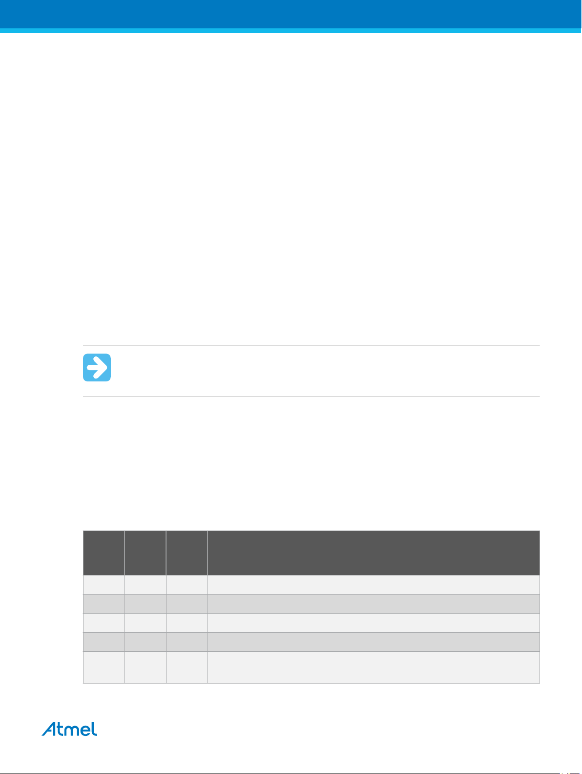
Table 3-1. Atmel-ICE JTAG Pin Description
Name AVR
port
pin
SAM
port
pin
Description
TCK 1 4 Test Clock (clock signal from the Atmel-ICE into the target device).
TMS 5 2 Test Mode Select (control signal from the Atmel-ICE into the target device).
TDI 9 8 Test Data In (data transmitted from the Atmel-ICE into the target device).
TDO 3 6 Test Data Out (data transmitted from the target device into the Atmel-ICE).
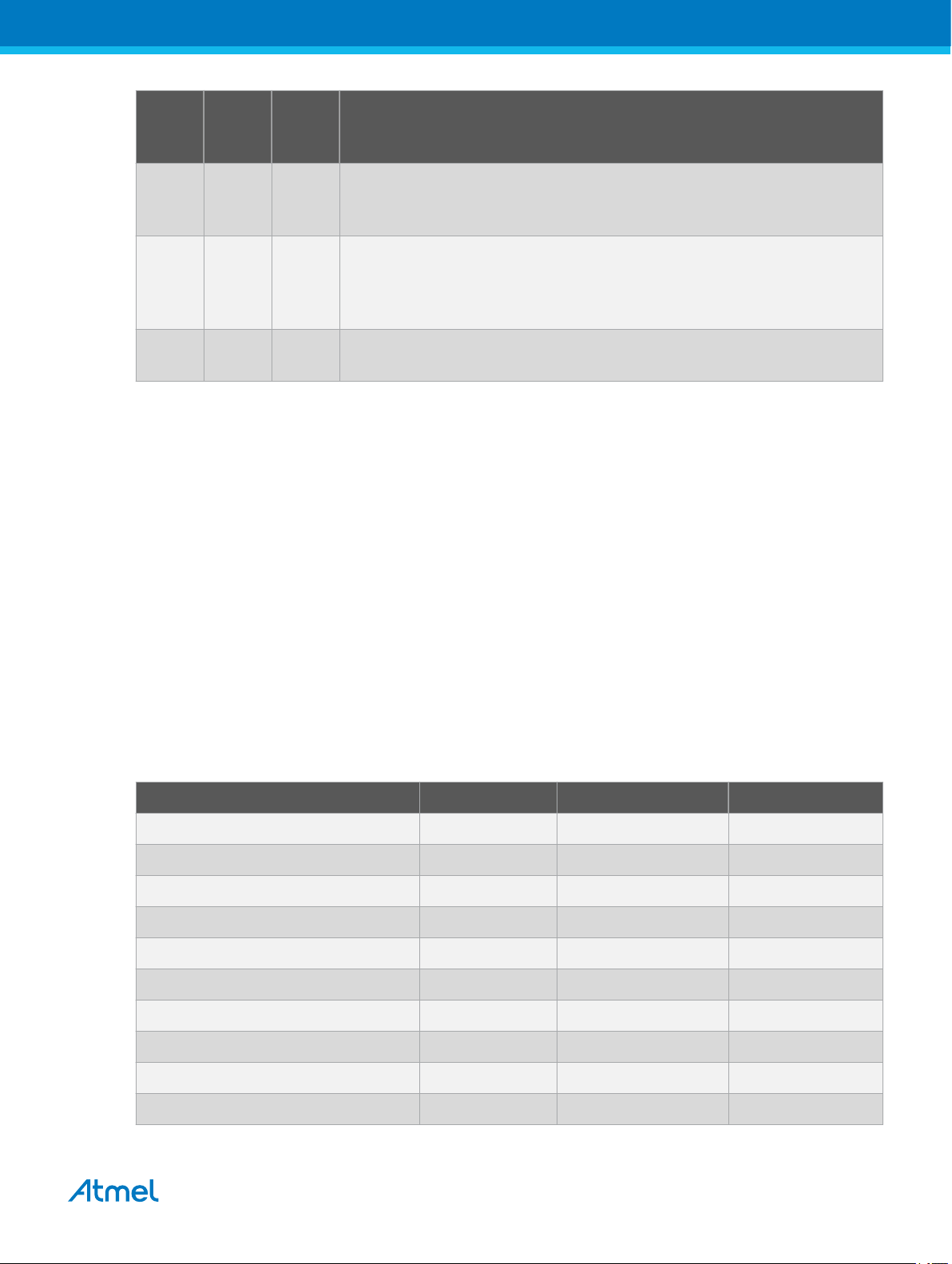
nTRST 8 - Test Reset (optional, only on some AVR devices). Used to reset the JTAG
TAP controller.
Atmel Atmel-ICE [USER GUIDE]
Atmel-42330C-Atmel-ICE_User Guide-10/2016
16
Page 17
Name AVR
port
pin
SAM
port
pin
nSRST 6 10 Reset (optional). Used to reset the target device. Connecting this pin is
recommended since it allows the Atmel-ICE to hold the target device in a
reset state, which can be essential to debugging in certain scenarios.
VTG 4 1 Target voltage reference. The Atmel-ICE samples the target voltage on this
pin in order to power the level converters correctly. The Atmel-ICE draws
less than 3mA from this pin in debugWIRE mode and less than 1mA in
other modes.
GND 2, 10 3, 5, 9 Ground. All must be connected to ensure that the Atmel-ICE and the target
device share the same ground reference.
3.3. Connecting to an aWire Target
The aWire interface requires only one data line in addition to VCC and GND. On the target this line is the
nRESET line, although the debugger uses the JTAG TDO line as the data line.
The recommended pinout for the 6-pin aWire connector is shown in Figure 4-8.
Connection to a 6-pin 100-mil aWire header
Description
Use the 6-pin 100-mil tap on the flat cable (included in some kits) to connect to a standard 100-mil aWire
header.
Connection to a 6-pin 50-mil aWire header
Use the adapter board (included in some kits) to connect to a standard 50-mil aWire header.
Connection to a custom 100-mil header
The 10-pin mini-squid cable should be used to connect between the Atmel-ICE AVR connector port and
the target board. Three connections are required, as described in the table below.
Table 3-2. Atmel-ICE aWire Pin Mapping
Atmel-ICE AVR port pins Target pins Mini-squid pin aWire pinout
Pin 1 (TCK) 1
Pin 2 (GND) GND 2 6
Pin 3 (TDO) DATA 3 1
Pin 4 (VTG) VTG 4 2
Pin 5 (TMS) 5
Pin 6 (nSRST) 6
Pin 7 (Not connected) 7
Pin 8 (nTRST) 8
Pin 9 (TDI) 9
Pin 10 (GND) 0
Atmel Atmel-ICE [USER GUIDE]
Atmel-42330C-Atmel-ICE_User Guide-10/2016
17
Page 18
3.4. Connecting to a PDI Target
The recommended pinout for the 6-pin PDI connector is shown in Figure 4-11.
Connection to a 6-pin 100-mil PDI header
Use the 6-pin 100-mil tap on the flat cable (included in some kits) to connect to a standard 100-mil PDI
header.
Connection to a 6-pin 50-mil PDI header
Use the adapter board (included in some kits) to connect to a standard 50-mil PDI header.
Connection to a custom 100-mil header
The 10-pin mini-squid cable should be used to connect between the Atmel-ICE AVR connector port and
the target board. Four connections are required, as described in the table below.
Important:
The pinout required is different from the JTAGICE mkII JTAG probe, where PDI_DATA is
connected to pin 9. The Atmel-ICE is compatible with the pinout used by the Atmel-ICE,
JTAGICE3, AVR ONE!, and AVR Dragon™ products.
Table 3-3. Atmel-ICE PDI Pin Mapping
Atmel-ICE AVR port pin Target pins Mini-squid pin Atmel STK600 PDI pinout
Pin 1 (TCK) 1
Pin 2 (GND) GND 2 6
Pin 3 (TDO) PDI_DATA 3 1
Pin 4 (VTG) VTG 4 2
Pin 5 (TMS) 5
Pin 6 (nSRST) PDI_CLK 6 5
Pin 7 (not connected) 7
Pin 8 (nTRST) 8
Pin 9 (TDI) 9
Pin 10 (GND) 0
3.5. Connecting to a UPDI Target
The recommended pinout for the 6-pin UPDI connector is shown in Figure 4-12.
Connection to a 6-pin 100-mil UPDI header
Use the 6-pin 100-mil tap on the flat cable (included in some kits) to connect to a standard 100-mil UPDI
header.
Connection to a 6-pin 50-mil UPDI header
Use the adapter board (included in some kits) to connect to a standard 50-mil UPDI header.
Atmel Atmel-ICE [USER GUIDE]
Atmel-42330C-Atmel-ICE_User Guide-10/2016
18
Page 19
Connection to a custom 100-mil header
The 10-pin mini-squid cable should be used to connect between the Atmel-ICE AVR connector port and
the target board. Three connections are required, as described in the table below.
Table 3-4. Atmel-ICE UPDI Pin Mapping
Atmel-ICE AVR port pin Target pins Mini-squid pin Atmel STK600 UPDI pinout
Pin 1 (TCK) 1
Pin 2 (GND) GND 2 6
Pin 3 (TDO) UPDI_DATA 3 1
Pin 4 (VTG) VTG 4 2
Pin 5 (TMS) 5
Pin 6 (nSRST) [/RESET sense] 6 5
Pin 7 (Not connected) 7
Pin 8 (nTRST) 8
Pin 9 (TDI) 9
Pin 10 (GND) 0
3.6. Connecting to a debugWIRE Target
The recommended pinout for the 6-pin debugWIRE (SPI) connector is shown in Table 3-6.
Connection to a 6-pin 100-mil SPI header
Use the 6-pin 100-mil tap on the flat cable (included in some kits) to connect to a standard 100-mil SPI
header.
Connection to a 6-pin 50-mil SPI header
Use the adapter board (included in some kits) to connect to a standard 50-mil SPI header.
Connection to a custom 100-mil header
The 10-pin mini-squid cable should be used to connect between the Atmel-ICE AVR connector port and
the target board. Three connections are required, as described in Table 3-5.
Although the debugWIRE interface only requires one signal line (RESET), VCC and GND to operate
correctly, it is advised to have access to the full SPI connector so that the debugWIRE interface can be
enabled and disabled using SPI programming.
When the DWEN fuse is enabled the SPI interface is overridden internally in order for the OCD module to
have control over the RESET pin. The debugWIRE OCD is capable of disabling itself temporarily (using
the button on the debugging tab in the properties dialog in Atmel Studio), thus releasing control of the
RESET line. The SPI interface is then available again (only if the SPIEN fuse is programmed), allowing
the DWEN fuse to be un-programmed using the SPI interface. If power is toggled before the DWEN fuse
is un-programmed, the debugWIRE module will again take control of the RESET pin.
Note:
It is highly advised to simply let Atmel Studio handle setting and clearing of the DWEN fuse.
Atmel Atmel-ICE [USER GUIDE]
Atmel-42330C-Atmel-ICE_User Guide-10/2016
19
Page 20

It is not possible to use the debugWIRE interface if the lockbits on the target AVR device are
programmed. Always be sure that the lockbits are cleared before programming the DWEN fuse and never
set the lockbits while the DWEN fuse is programmed. If both the debugWIRE enable fuse (DWEN) and
lockbits are set, one can use High Voltage Programming to do a chip erase, and thus clear the lockbits.
When the lockbits are cleared the debugWIRE interface will be re-enabled. The SPI Interface is only
capable of reading fuses, reading signature and performing a chip erase when the DWEN fuse is unprogrammed.
Table 3-5. Atmel-ICE debugWIRE Pin Mapping
Atmel-ICE AVR port pin Target pins Mini-squid pin
Pin 1 (TCK) 1
Pin 2 (GND) GND 2
Pin 3 (TDO) 3
Pin 4 (VTG) VTG 4
Pin 5 (TMS) 5
Pin 6 (nSRST) RESET 6
Pin 7 (Not connected) 7
Pin 8 (nTRST) 8
Pin 9 (TDI) 9
Pin 10 (GND) 0
3.7. Connecting to an SPI Target
The recommended pinout for the 6-pin SPI connector is shown in Figure 4-10.
Connection to a 6-pin 100-mil SPI header
Use the 6-pin 100-mil tap on the flat cable (included in some kits) to connect to a standard 100-mil SPI
header.
Connection to a 6-pin 50-mil SPI header
Use the adapter board (included in some kits) to connect to a standard 50-mil SPI header.
Connection to a custom 100-mil header
The 10-pin mini-squid cable should be used to connect between the Atmel-ICE AVR connector port and
the target board. Six connections are required, as described in the table below.
Important:
The SPI interface is effectively disabled when the debugWIRE enable fuse (DWEN) is
programmed, even if SPIEN fuse is also programmed. To re-enable the SPI interface, the
'disable debugWIRE' command must be issued while in a debugWIRE debugging session.
Disabling debugWIRE in this manner requires that the SPIEN fuse is already programmed. If
Atmel Studio fails to disable debugWIRE, it is probable because the SPIEN fuse is NOT
programmed. If this is the case, it is necessary to use a high-voltage programming interface to
program the SPIEN fuse.
Atmel Atmel-ICE [USER GUIDE]
Atmel-42330C-Atmel-ICE_User Guide-10/2016
20
Page 21

Info:
The SPI interface is often referred to as "ISP", since it was the first In System Programming
interface on Atmel AVR products. Other interfaces are now available for In System
Programming.
Table 3-6. Atmel-ICE SPI Pin Mapping
Atmel-ICE AVR port pins Target pins Mini-squid pin SPI pinout
Pin 1 (TCK) SCK 1 3
Pin 2 (GND) GND 2 6
Pin 3 (TDO) MISO 3 1
Pin 4 (VTG) VTG 4 2
Pin 5 (TMS) 5
Pin 6 (nSRST) /RESET 6 5
Pin 7 (not connected) 7
Pin 8 (nTRST) 8
Pin 9 (TDI) MOSI 9 4
Pin 10 (GND) 0
3.8. Connecting to a TPI Target
The recommended pinout for the 6-pin TPI connector is shown in Figure 4-13.
Connection to a 6-pin 100-mil TPI header
Use the 6-pin 100-mil tap on the flat cable (included in some kits) to connect to a standard 100-mil TPI
header.
Connection to a 6-pin 50-mil TPI header
Use the adapter board (included in some kits) to connect to a standard 50-mil TPI header.
Connection to a custom 100-mil header
The 10-pin mini-squid cable should be used to connect between the Atmel-ICE AVR connector port and
the target board. Six connections are required, as described in the table below.
Table 3-7. Atmel-ICE TPI Pin Mapping
Atmel-ICE AVR port pins Target pins Mini-squid pin TPI pinout
Pin 1 (TCK) CLOCK 1 3
Pin 2 (GND) GND 2 6
Pin 3 (TDO) DATA 3 1
Pin 4 (VTG) VTG 4 2
Pin 5 (TMS) 5
Atmel Atmel-ICE [USER GUIDE]
Atmel-42330C-Atmel-ICE_User Guide-10/2016
21
Page 22

Atmel-ICE AVR port pins Target pins Mini-squid pin TPI pinout
Pin 6 (nSRST) /RESET 6 5
Pin 7 (not connected) 7
Pin 8 (nTRST) 8
Pin 9 (TDI) 9
Pin 10 (GND) 0
3.9. Connecting to an SWD Target
The ARM SWD interface is a subset of the JTAG interface, making use of the TCK and TMS pins, which
means that when connecting to an SWD device, the 10-pin JTAG connector can technically be used. The
ARM JTAG and AVR JTAG connectors are, however, not pin-compatible, so this depends upon the layout
of the target board in use. When using an STK600 or a board making use of the AVR JTAG pinout, the
AVR connector port on the Atmel-ICE must be used. When connecting to a board, which makes use of
the ARM JTAG pinout, the SAM connector port on the Atmel-ICE must be used.
The recommended pinout for the 10-pin Cortex Debug connector is shown in Figure 4-4.
Connection to a 10-pin 50-mil Cortex header
Use the flat cable (included in some kits) to connect to a standard 50-mil Cortex header.
Connection to a 10-pin 100-mil Cortex-layout header
Use the adapter board (included in some kits) to connect to a 100-mil Cortex-pinout header.
Connection to a 20-pin 100-mil SAM header
Use the adapter board (included in some kits) to connect to a 20-pin 100-mil SAM header.
Connection to a custom 100-mil header
The 10-pin mini-squid cable should be used to connect between the Atmel-ICE AVR or SAM connector
port and the target board. Six connections are required, as described in the table below.
Table 3-8. Atmel-ICE SWD Pin Mapping
Name AVR
port
pin
SAM
port
pin
Description
SWDCLK1 4 Serial Wire Debug Clock.
SWDIO 5 2 Serial Wire Debug Data Input/Output.
SWO 3 6 Serial Wire Output (optional- not implemented on all devices).
nSRST 6 10 Reset.
VTG 4 1 Target voltage reference.
GND 2, 10 3, 5, 9 Ground.
Atmel Atmel-ICE [USER GUIDE]
Atmel-42330C-Atmel-ICE_User Guide-10/2016
22
Page 23

3.10. Connecting to Data Gateway Interface
The Atmel-ICE supports a limited Data Gateway Interface (DGI) when debugging and programming is not
in use. Functionality is identical to that found on Atmel Xplained Pro kits powered by the Atmel EDBG
device.
The Data Gateway Interface is an interface for streaming data from the target device to a computer. This
is meant as an aid in application debugging as well as for demonstration of features in the application
running on the target device.
DGI consists of multiple channels for data streaming. The Atmel-ICE supports the following modes:
• USART
• SPI
Table 3-9. Atmel-ICE DGI USART Pinout
AVR port SAM port DGI USART pin Description
3 6 TX Transmit pin from Atmel-ICE to the target device
4 1 VTG Target voltage (reference voltage)
8 7 RX Receive pin from the target device to Atmel-ICE
9 8 CLK USART clock
2, 10 3, 5, 9 GND Ground
Table 3-10. Atmel-ICE DGI SPI Pinout
AVR port SAM port DGI SPI pin Description
1 4 SCK SPI clock
3 6 MISO Master In Slave Out
4 1 VTG Target voltage (reference voltage)
5 2 nCS Chip select active low
9 8 MOSI Master Out Slave In
2, 10 3, 5, 9 GND Ground
Important: SPI and USART interfaces can not be used simultaneously.
Important: DGI and programming or debugging cannot be used simultaneously.
Atmel Atmel-ICE [USER GUIDE]
Atmel-42330C-Atmel-ICE_User Guide-10/2016
23
Page 24

4. On-chip Debugging
4.1. Introduction
On-chip Debugging
An on-chip debug module is a system allowing a developer to monitor and control execution on a device
from an external development platform, usually through a device known as a debugger or debug adapter.
With an OCD system the application can be executed whilst maintaining exact electrical and timing
characteristics in the target system, while being able to stop execution conditionally or manually and
inspect program flow and memory.
Run Mode
When in Run mode, the execution of code is completely independent of the Atmel-ICE. The Atmel-ICE
will continuously monitor the target device to see if a break condition has occurred. When this happens
the OCD system will interrogate the device through its debug interface, allowing the user to view the
internal state of the device.
Stopped Mode
When a breakpoint is reached, the program execution is halted, but some I/O may continue to run as if no
breakpoint had occurred. For example, assume that a USART transmit has just been initiated when a
breakpoint is reached. In this case the USART continues to run at full speed completing the transmission,
even though the core is in stopped mode.
Hardware Breakpoints
The target OCD module contains a number of program counter comparators implemented in the
hardware. When the program counter matches the value stored in one of the comparator registers, the
OCD enters stopped mode. Since hardware breakpoints require dedicated hardware on the OCD module,
the number of breakpoints available depends upon the size of the OCD module implemented on the
target. Usually one such hardware comparator is ‘reserved’ by the debugger for internal use.
Software Breakpoints
A software breakpoint is a BREAK instruction placed in program memory on the target device. When this
instruction is loaded, program execution will break and the OCD enters stopped mode. To continue
execution a "start" command has to be given from the OCD. Not all Atmel devices have OCD modules
supporting the BREAK instruction.
4.2. SAM Devices with JTAG/SWD
All SAM devices feature the SWD interface for programming and debugging. In addition, some SAM
devices feature a JTAG interface with identical functionality. Check the device datasheet for supported
interfaces of that device.
4.2.1. ARM CoreSight Components
Atmel ARM Cortex-M based microcontrollers implement CoreSight compliant OCD components. The
features of these components can vary from device to device. For further information consult the device's
datasheet as well as CoreSight documentation provided by ARM.
Atmel Atmel-ICE [USER GUIDE]
Atmel-42330C-Atmel-ICE_User Guide-10/2016
24
Page 25

4.2.2. JTAG Physical Interface
The JTAG interface consists of a 4-wire Test Access Port (TAP) controller that is compliant with the IEEE
1149.1 standard. The IEEE standard was developed to provide an industry-standard way to efficiently test
circuit board connectivity (Boundary Scan). Atmel AVR and SAM devices have extended this functionality
to include full Programming and On-chip Debugging support.
Figure 4-1. JTAG Interface Basics
programmer /
debugger
4.2.2.1. SAM JTAG Pinout (Cortex-M debug connector)
When designing an application PCB which includes an Atmel SAM with the JTAG interface, it is
recommended to use the pinout as shown in the figure below. Both 100-mil and 50-mil variants of this
pinout are supported, depending on the cabling and adapters included with the particular kit.
TCK
TMS
TDI
TDO
®
Vcc
Atmel
target
device
Figure 4-2. SAM JTAG Header Pinout
1 2
VCC
GND
GND
(KEY)
GND
SAM JTAG
Table 4-1. SAM JTAG Pin Description
TMS
TCK
TDO
TDI
nRESET
Name Pin Description
TCK 4 Test Clock (clock signal from the Atmel-ICE into the target device).
TMS 2 Test Mode Select (control signal from the Atmel-ICE into the target device).
TDI 8 Test Data In (data transmitted from the Atmel-ICE into the target device).
TDO 6 Test Data Out (data transmitted from the target device into the Atmel-ICE).
nRESET 10 Reset (optional). Used to reset the target device. Connecting this pin is
recommended since it allows the Atmel-ICE to hold the target device in a reset
state, which can be essential to debugging in certain scenarios.
VTG 1 Target voltage reference. The Atmel-ICE samples the target voltage on this pin in
order to power the level converters correctly. The Atmel-ICE draws less than 1mA
from this pin in this mode.
GND 3, 5, 9 Ground. All must be connected to ensure that the Atmel-ICE and the target device
share the same ground reference.
KEY 7 Connected internally to the TRST pin on the AVR connector. Recommended as not
connected.
Atmel Atmel-ICE [USER GUIDE]
Atmel-42330C-Atmel-ICE_User Guide-10/2016
25
Page 26

Tip: Remember to include a decoupling capacitor between pin 1 and GND.
4.2.2.2. JTAG Daisy Chaining
The JTAG interface allows for several devices to be connected to a single interface in a daisy chain
configuration. The target devices must all be powered by the same supply voltage, share a common
ground node, and must be connected as shown in the figure below.
Figure 4-3. JTAG Daisy Chain
TCK
TMS
programmer /
debugger
TDI
target
device
1
target
device
2
target
device
3
TDO
When connecting devices in a daisy chain, the following points must be considered:
• All devices must share a common ground, connected to GND on the Atmel-ICE probe
• All devices must be operating on the same target voltage. VTG on the Atmel-ICE must be
connected to this voltage.
• TMS and TCK are connected in parallel; TDI and TDO are connected in a serial chain.
• nSRST on the Atmel-ICE probe must be connected to RESET on the devices if any of the devices
in the chain disables its JTAG port
• "Devices before" refers to the number of JTAG devices that the TDI signal has to pass through in
the daisy chain before reaching the target device. Similarly "devices after" is the number of devices
that the signal has to pass through after the target device before reaching the Atmel-ICE TDO pin.
• "Instruction bits "before" and "after" refers to the total sum of all JTAG devices' instruction register
lengths, which are connected before and after the target device in the daisy chain
• The total IR length (instruction bits before + Atmel target device IR length + instruction bits after) is
limited to a maximum of 256 bits. The number of devices in the chain is limited to 15 before and 15
after.
Tip:
Daisy chaining example: TDI → ATmega1280 → ATxmega128A1 → ATUC3A0512 → TDO.
In order to connect to the Atmel AVR XMEGA® device, the daisy chain settings are:
• Devices before: 1
• Devices after: 1
• Instruction bits before: 4 (8-bit AVR devices have 4 IR bits)
Atmel Atmel-ICE [USER GUIDE]
Atmel-42330C-Atmel-ICE_User Guide-10/2016
26
Page 27

• Instruction bits after: 5 (32-bit AVR devices have 5 IR bits)
Table 4-2. IR Lengths of Atmel MCUs
Device type IR length
AVR 8-bit 4 bits
AVR 32-bit 5 bits
SAM 4 bits
4.2.3. Connecting to a JTAG Target
The Atmel-ICE is equipped with two 50-mil 10-pin JTAG connectors. Both connectors are directly
electrically connected, but conform to two different pinouts; the AVR JTAG header and the ARM Cortex
Debug header. The connector should be selected based on the pinout of the target board, and not the
target MCU type - for example a SAM device mounted in an AVR STK600 stack should use the AVR
header.
The recommended pinout for the 10-pin AVR JTAG connector is shown in Figure 4-6.
The recommended pinout for the 10-pin ARM Cortex Debug connector is shown in Figure 4-2.
Direct connection to a standard 10-pin 50-mil header
Use the 50-mil 10-pin flat cable (included in some kits) to connect directly to a board supporting this
header type. Use the AVR connector port on the Atmel-ICE for headers with the AVR pinout, and the SAM
connector port for headers complying with the ARM Cortex Debug header pinout.
The pinouts for both 10-pin connector ports are shown below.
Connection to a standard 10-pin 100-mil header
Use a standard 50-mil to 100-mil adapter to connect to 100-mil headers. An adapter board (included in
some kits) can be used for this purpose, or alternatively the JTAGICE3 adapter can be used for AVR
targets.
Important:
The JTAGICE3 100-mil adapter cannot be used with the SAM connector port, since pins 2 and
10 (AVR GND) on the adapter are connected.
Connection to a custom 100-mil header
If your target board does not have a compliant 10-pin JTAG header in 50- or 100-mil, you can map to a
custom pinout using the 10-pin "mini-squid" cable (included in some kits), which gives access to ten
individual 100-mil sockets.
Connection to a 20-pin 100-mil header
Use the adapter board (included in some kits) to connect to targets with a 20-pin 100-mil header.
Atmel Atmel-ICE [USER GUIDE]
Atmel-42330C-Atmel-ICE_User Guide-10/2016
27
Page 28

Table 4-3. Atmel-ICE JTAG Pin Description
Name AVR
port
pin
SAM
port
pin
Description
TCK 1 4 Test Clock (clock signal from the Atmel-ICE into the target device).
TMS 5 2 Test Mode Select (control signal from the Atmel-ICE into the target device).
TDI 9 8 Test Data In (data transmitted from the Atmel-ICE into the target device).
TDO 3 6 Test Data Out (data transmitted from the target device into the Atmel-ICE).
nTRST 8 - Test Reset (optional, only on some AVR devices). Used to reset the JTAG
TAP controller.
nSRST 6 10 Reset (optional). Used to reset the target device. Connecting this pin is
recommended since it allows the Atmel-ICE to hold the target device in a
reset state, which can be essential to debugging in certain scenarios.
VTG 4 1 Target voltage reference. The Atmel-ICE samples the target voltage on this
pin in order to power the level converters correctly. The Atmel-ICE draws
less than 3mA from this pin in debugWIRE mode and less than 1mA in
other modes.
GND 2, 10 3, 5, 9 Ground. All must be connected to ensure that the Atmel-ICE and the target
device share the same ground reference.
4.2.4. SWD Physical Interface
The ARM SWD interface is a subset of the JTAG interface, making use of TCK and TMS pins. The ARM
JTAG and AVR JTAG connectors are, however, not pin-compatible, so when designing an application
PCB, which uses a SAM device with SWD or JTAG interface, it is recommended to use the ARM pinout
shown in the figure below. The SAM connector port on the Atmel-ICE can connect directly to this pinout.
Figure 4-4. Recommended ARM SWD/JTAG Header Pinout
The Atmel-ICE is capable of streaming UART-format ITM trace to the host computer. Trace is captured on
the TRACE/SWO pin of the 10-pin header (JTAG TDO pin). Data is buffered internally on the Atmel-ICE
and is sent over the HID interface to the host computer. The maximum reliable data rate is about 3MB/s.
4.2.5. Connecting to an SWD Target
The ARM SWD interface is a subset of the JTAG interface, making use of the TCK and TMS pins, which
means that when connecting to an SWD device, the 10-pin JTAG connector can technically be used. The
ARM JTAG and AVR JTAG connectors are, however, not pin-compatible, so this depends upon the layout
of the target board in use. When using an STK600 or a board making use of the AVR JTAG pinout, the
AVR connector port on the Atmel-ICE must be used. When connecting to a board, which makes use of
the ARM JTAG pinout, the SAM connector port on the Atmel-ICE must be used.
VCC
GND
GND
(KEY)
GND
SAM SWD
1 2
SWDIO
SWDCLK
SWO
(NC)
nRESET
The recommended pinout for the 10-pin Cortex Debug connector is shown in Figure 4-4.
Connection to a 10-pin 50-mil Cortex header
Atmel Atmel-ICE [USER GUIDE]
Atmel-42330C-Atmel-ICE_User Guide-10/2016
28
Page 29

Use the flat cable (included in some kits) to connect to a standard 50-mil Cortex header.
Connection to a 10-pin 100-mil Cortex-layout header
Use the adapter board (included in some kits) to connect to a 100-mil Cortex-pinout header.
Connection to a 20-pin 100-mil SAM header
Use the adapter board (included in some kits) to connect to a 20-pin 100-mil SAM header.
Connection to a custom 100-mil header
The 10-pin mini-squid cable should be used to connect between the Atmel-ICE AVR or SAM connector
port and the target board. Six connections are required, as described in the table below.
Table 4-4. Atmel-ICE SWD Pin Mapping
Name AVR
port
pin
SAM
port
pin
SWDCLK1 4 Serial Wire Debug Clock.
SWDIO 5 2 Serial Wire Debug Data Input/Output.
SWO 3 6 Serial Wire Output (optional- not implemented on all devices).
nSRST 6 10 Reset.
VTG 4 1 Target voltage reference.
GND 2, 10 3, 5, 9 Ground.
4.2.6. Special Considerations
ERASE pin
Some SAM devices include an ERASE pin which is asserted to perform a complete chip erase and
unlock devices on which the security bit is set. This feature is coupled to the device itself as well as the
flash controller and is not part of the ARM core.
The ERASE pin is NOT part of any debug header, and the Atmel-ICE is thus unable to assert this signal
to unlock a device. In such cases the user should perform the erase manually before starting a debug
session.
Description
Physical interfaces
JTAG interface
The RESET line should always be connected so that the Atmel-ICE can enable the JTAG interface.
SWD interface
The RESET line should always be connected so that the Atmel-ICE can enable the SWD interface.
4.3. AVR UC3 Devices with JTAG/aWire
All AVR UC3 devices feature the JTAG interface for programming and debugging. In addition, some AVR
UC3 devices feature the aWire interface with identical functionality using a single wire. Check the device
datasheet for supported interfaces of that device.
Atmel Atmel-ICE [USER GUIDE]
Atmel-42330C-Atmel-ICE_User Guide-10/2016
29
Page 30

4.3.1. Atmel AVR UC3 On-chip Debug System
The Atmel AVR UC3 OCD system is designed in accordance with the Nexus 2.0 standard (IEEE-ISTO
5001™-2003), which is a highly flexible and powerful open on-chip debug standard for 32-bit
microcontrollers. It supports the following features:
• Nexus compliant debug solution
• OCD supports any CPU speed
• Six program counter hardware breakpoints
• Two data breakpoints
• Breakpoints can be configured as watchpoints
• Hardware breakpoints can be combined to give break on ranges
• Unlimited number of user program breakpoints (using BREAK)
• Real-time program counter branch tracing, data trace, process trace (supported only by debuggers
with parallel trace capture port)
For more information regarding the AVR UC3 OCD system, consult the AVR32UC Technical Reference
Manuals, located on www.atmel.com/uc3.
4.3.2. JTAG Physical Interface
The JTAG interface consists of a 4-wire Test Access Port (TAP) controller that is compliant with the IEEE
1149.1 standard. The IEEE standard was developed to provide an industry-standard way to efficiently test
circuit board connectivity (Boundary Scan). Atmel AVR and SAM devices have extended this functionality
to include full Programming and On-chip Debugging support.
Figure 4-5. JTAG Interface Basics
4.3.2.1. AVR JTAG Pinout
When designing an application PCB, which includes an Atmel AVR with the JTAG interface, it is
recommended to use the pinout as shown in the figure below. Both 100-mil and 50-mil variants of this
pinout are supported, depending on the cabling and adapters included with the particular kit.
programmer /
debugger
TCK
TMS
TDI
TDO
®
Vcc
Atmel
target
device
Figure 4-6. AVR JTAG Header Pinout
TCK
TDO
TMS
(NC)
TDI
AVR JTAG
1 2
GND
VCC
/RESET
(TRST)
GND
Atmel Atmel-ICE [USER GUIDE]
Atmel-42330C-Atmel-ICE_User Guide-10/2016
30
Page 31

Table 4-5. AVR JTAG Pin Description
Name Pin Description
TCK 1 Test Clock (clock signal from the Atmel-ICE into the target device).
TMS 5 Test Mode Select (control signal from the Atmel-ICE into the target device).
TDI 9 Test Data In (data transmitted from the Atmel-ICE into the target device).
TDO 3 Test Data Out (data transmitted from the target device into the Atmel-ICE).
nTRST 8 Test Reset (optional, only on some AVR devices). Used to reset the JTAG TAP
controller.
nSRST 6 Reset (optional). Used to reset the target device. Connecting this pin is
recommended since it allows the Atmel-ICE to hold the target device in a reset
state, which can be essential to debugging in certain scenarios.
VTG 4 Target voltage reference. The Atmel-ICE samples the target voltage on this pin in
order to power the level converters correctly. The Atmel-ICE draws less than 3mA
from this pin in debugWIRE mode and less than 1mA in other modes.
GND 2, 10 Ground. Both must be connected to ensure that the Atmel-ICE and the target
device share the same ground reference.
Tip: Remember to include a decoupling capacitor between pin 4 and GND.
4.3.2.2. JTAG Daisy Chaining
The JTAG interface allows for several devices to be connected to a single interface in a daisy chain
configuration. The target devices must all be powered by the same supply voltage, share a common
ground node, and must be connected as shown in the figure below.
Figure 4-7. JTAG Daisy Chain
programmer /
debugger
TCK
TMS
TDI
TDO
target
device
1
target
device
2
target
device
3
When connecting devices in a daisy chain, the following points must be considered:
• All devices must share a common ground, connected to GND on the Atmel-ICE probe
• All devices must be operating on the same target voltage. VTG on the Atmel-ICE must be
connected to this voltage.
Atmel Atmel-ICE [USER GUIDE]
Atmel-42330C-Atmel-ICE_User Guide-10/2016
31
Page 32

• TMS and TCK are connected in parallel; TDI and TDO are connected in a serial chain.
• nSRST on the Atmel-ICE probe must be connected to RESET on the devices if any of the devices
in the chain disables its JTAG port
• "Devices before" refers to the number of JTAG devices that the TDI signal has to pass through in
the daisy chain before reaching the target device. Similarly "devices after" is the number of devices
that the signal has to pass through after the target device before reaching the Atmel-ICE TDO pin.
• "Instruction bits "before" and "after" refers to the total sum of all JTAG devices' instruction register
lengths, which are connected before and after the target device in the daisy chain
• The total IR length (instruction bits before + Atmel target device IR length + instruction bits after) is
limited to a maximum of 256 bits. The number of devices in the chain is limited to 15 before and 15
after.
Tip:
Daisy chaining example: TDI → ATmega1280 → ATxmega128A1 → ATUC3A0512 → TDO.
In order to connect to the Atmel AVR XMEGA® device, the daisy chain settings are:
• Devices before: 1
• Devices after: 1
• Instruction bits before: 4 (8-bit AVR devices have 4 IR bits)
• Instruction bits after: 5 (32-bit AVR devices have 5 IR bits)
Table 4-6. IR Lengths of Atmel MCUs
Device type IR length
AVR 8-bit 4 bits
AVR 32-bit 5 bits
SAM 4 bits
4.3.3. Connecting to a JTAG Target
The Atmel-ICE is equipped with two 50-mil 10-pin JTAG connectors. Both connectors are directly
electrically connected, but conform to two different pinouts; the AVR JTAG header and the ARM Cortex
Debug header. The connector should be selected based on the pinout of the target board, and not the
target MCU type - for example a SAM device mounted in an AVR STK600 stack should use the AVR
header.
The recommended pinout for the 10-pin AVR JTAG connector is shown in Figure 4-6.
The recommended pinout for the 10-pin ARM Cortex Debug connector is shown in Figure 4-2.
Direct connection to a standard 10-pin 50-mil header
Use the 50-mil 10-pin flat cable (included in some kits) to connect directly to a board supporting this
header type. Use the AVR connector port on the Atmel-ICE for headers with the AVR pinout, and the SAM
connector port for headers complying with the ARM Cortex Debug header pinout.
The pinouts for both 10-pin connector ports are shown below.
Connection to a standard 10-pin 100-mil header
Atmel Atmel-ICE [USER GUIDE]
Atmel-42330C-Atmel-ICE_User Guide-10/2016
32
Page 33

Use a standard 50-mil to 100-mil adapter to connect to 100-mil headers. An adapter board (included in
some kits) can be used for this purpose, or alternatively the JTAGICE3 adapter can be used for AVR
targets.
Important:
The JTAGICE3 100-mil adapter cannot be used with the SAM connector port, since pins 2 and
10 (AVR GND) on the adapter are connected.
Connection to a custom 100-mil header
If your target board does not have a compliant 10-pin JTAG header in 50- or 100-mil, you can map to a
custom pinout using the 10-pin "mini-squid" cable (included in some kits), which gives access to ten
individual 100-mil sockets.
Connection to a 20-pin 100-mil header
Use the adapter board (included in some kits) to connect to targets with a 20-pin 100-mil header.
Table 4-7. Atmel-ICE JTAG Pin Description
Name AVR
port
pin
SAM
port
pin
Description
TCK 1 4 Test Clock (clock signal from the Atmel-ICE into the target device).
TMS 5 2 Test Mode Select (control signal from the Atmel-ICE into the target device).
TDI 9 8 Test Data In (data transmitted from the Atmel-ICE into the target device).
TDO 3 6 Test Data Out (data transmitted from the target device into the Atmel-ICE).
nTRST 8 - Test Reset (optional, only on some AVR devices). Used to reset the JTAG
TAP controller.
nSRST 6 10 Reset (optional). Used to reset the target device. Connecting this pin is
recommended since it allows the Atmel-ICE to hold the target device in a
reset state, which can be essential to debugging in certain scenarios.
VTG 4 1 Target voltage reference. The Atmel-ICE samples the target voltage on this
pin in order to power the level converters correctly. The Atmel-ICE draws
less than 3mA from this pin in debugWIRE mode and less than 1mA in
other modes.
GND 2, 10 3, 5, 9 Ground. All must be connected to ensure that the Atmel-ICE and the target
device share the same ground reference.
4.3.4. aWire Physical Interface
The aWire interface makes use of the RESET wire of the AVR device to allow programming and
debugging functions. A special enable sequence is transmitted by the Atmel-ICE, which disables the
default RESET functionality of the pin.
When designing an application PCB, which includes an Atmel AVR with the aWire interface, it is
recommended to use the pinout as shown in Figure 4-8. Both 100-mil and 50-mil variants of this pinout
are supported, depending on the cabling and adapters included with the particular kit.
Atmel Atmel-ICE [USER GUIDE]
Atmel-42330C-Atmel-ICE_User Guide-10/2016
33
Page 34

Figure 4-8. aWire Header Pinout
Tip:
Since aWire is a half-duplex interface, a pull-up resistor on the RESET line in the order of 47kΩ
is recommended to avoid false start-bit detection when changing direction.
The aWire interface can be used as both a programming and debugging interface. All features of the
OCD system available through the 10-pin JTAG interface can also be accessed using aWire.
4.3.5. Connecting to an aWire Target
The aWire interface requires only one data line in addition to VCC and GND. On the target this line is the
nRESET line, although the debugger uses the JTAG TDO line as the data line.
The recommended pinout for the 6-pin aWire connector is shown in Figure 4-8.
Connection to a 6-pin 100-mil aWire header
Use the 6-pin 100-mil tap on the flat cable (included in some kits) to connect to a standard 100-mil aWire
header.
(RESET_N) DATA VCC
(NC)
(NC)
1 2
(NC)
GND
aWire
Connection to a 6-pin 50-mil aWire header
Use the adapter board (included in some kits) to connect to a standard 50-mil aWire header.
Connection to a custom 100-mil header
The 10-pin mini-squid cable should be used to connect between the Atmel-ICE AVR connector port and
the target board. Three connections are required, as described in the table below.
Table 4-8. Atmel-ICE aWire Pin Mapping
Atmel-ICE AVR port pins Target pins Mini-squid pin aWire pinout
Pin 1 (TCK) 1
Pin 2 (GND) GND 2 6
Pin 3 (TDO) DATA 3 1
Pin 4 (VTG) VTG 4 2
Pin 5 (TMS) 5
Pin 6 (nSRST) 6
Pin 7 (Not connected) 7
Pin 8 (nTRST) 8
Pin 9 (TDI) 9
Pin 10 (GND) 0
Atmel Atmel-ICE [USER GUIDE]
Atmel-42330C-Atmel-ICE_User Guide-10/2016
34
Page 35

4.3.6. Special Considerations
JTAG interface
On some Atmel AVR UC3 devices the JTAG port is not enabled by default. When using these devices it is
essential to connect the RESET line so that the Atmel-ICE can enable the JTAG interface.
aWire interface
The baud rate of aWire communications depends upon the frequency of the system clock, since data
must be synchronized between these two domains. The Atmel-ICE will automatically detect that the
system clock has been lowered, and re-calibrate its baud rate accordingly. The automatic calibration only
works down to a system clock frequency of 8kHz. Switching to a lower system clock during a debug
session may cause contact with the target to be lost.
If required, the aWire baud rate can be restricted by setting the aWire clock parameter. Automatic
detection will still work, but a ceiling value will be imposed on the results.
Any stabilizing capacitor connected to the RESET pin must be disconnected when using aWire since it
will interfere with correct operation of the interface. A weak external pullup (10kΩ or higher) on this line is
recommended.
Shutdown sleep mode
Some AVR UC3 devices have an internal regulator that can be used in 3.3V supply mode with 1.8V
regulated I/O lines. This means that the internal regulator powers both the core and most of the I/O. Only
Atmel AVR ONE! debugger supports debugging while using sleep modes where this regulator is shut off.
4.3.7. EVTI / EVTO Usage
The EVTI and EVTO pins are not accessible on the Atmel-ICE. However, they can still be used in
conjunction with other external equipment.
EVTI can be used for the following purposes:
• The target can be forced to stop execution in response to an external event. If the Event In Control
(EIC) bits in the DC register are written to 0b01, high-to-low transition on the EVTI pin will generate
a breakpoint condition. EVTI must remain low for one CPU clock cycle to guarantee that a
breakpoint is triggered. The External Breakpoint bit (EXB) in DS is set when this occurs.
• Generating trace synchronization messages. Not used by the Atmel-ICE.
EVTO can be used for the following purposes:
• Indicating that the CPU has entered debug mode. Setting the EOS bits in DC to 0b01 causes the
EVTO pin to be pulled low for one CPU clock cycle when the target device enters debug mode.
This signal can be used as a trigger source for an external oscilloscope.
• Indicating that the CPU has reached a breakpoint or watchpoint. By setting the EOC bit in a
corresponding Breakpoint/Watchpoint Control Register, the breakpoint or watchpoint status is
indicated on the EVTO pin. The EOS bits in DC must be set to 0xb10 to enable this feature. The
EVTO pin can then be connected to an external oscilloscope in order to examine watchpoint timing.
• Generating trace timing signals. Not used by the Atmel-ICE.
4.4. tinyAVR, megaAVR, and XMEGA Devices
AVR devices feature various programming and debugging interfaces. Check the device datasheet for
supported interfaces of that device.
Atmel Atmel-ICE [USER GUIDE]
Atmel-42330C-Atmel-ICE_User Guide-10/2016
35
Page 36

• Some tinyAVR® devices have a TPI interface. TPI can be used for programming the device only,
and these devices do not have on-chip debug capability at all.
• Some tinyAVR devices and some megaAVR devices have the debugWIRE interface, which
connects to an on-chip debug system known as tinyOCD. All devices with debugWIRE also have
the SPI interface for in-system programming.
• Some megaAVR devices have a JTAG interface for programming and debugging, with an on-chip
debug system also known as megaOCD. All devices with JTAG also feature the SPI interface as an
alternative interface for in-system programming.
• All AVR XMEGA devices have the PDI interface for programming and debugging. Some AVR
XMEGA devices also have a JTAG interface with identical functionality.
• New tinyAVR devices have a UPDI interface, which is used for programming and debugging
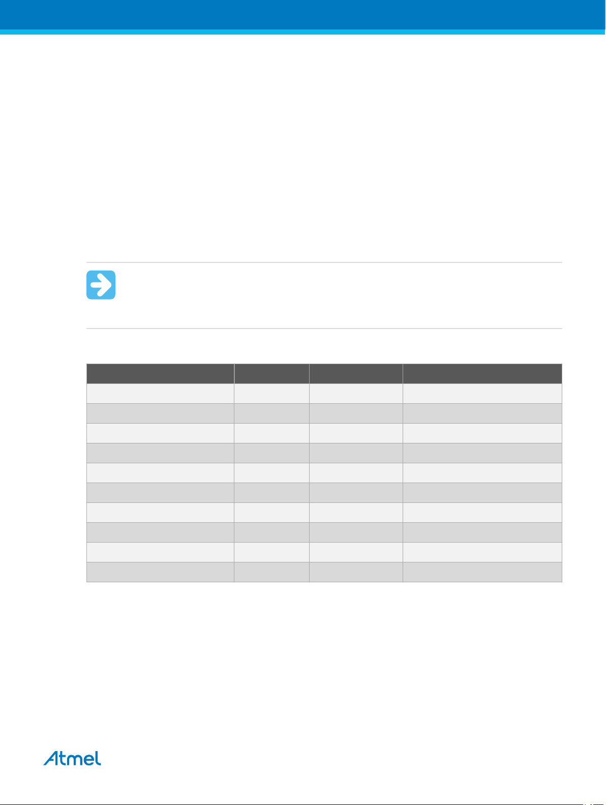
Table 4-9. Programming and Debugging Interfaces Summary
UPDI TPI SPI debugWIREJTAG PDI aWire SWD
tinyAVR New
devices
megaAV
R
AVR
XMEGA
AVR UC All
SAM Some
4.4.1. JTAG Physical Interface
The JTAG interface consists of a 4-wire Test Access Port (TAP) controller that is compliant with the IEEE
1149.1 standard. The IEEE standard was developed to provide an industry-standard way to efficiently test
circuit board connectivity (Boundary Scan). Atmel AVR and SAM devices have extended this functionality
to include full Programming and On-chip Debugging support.
Figure 4-9. JTAG Interface Basics
Some
devices
Some
devices
All
devices
Some
devices
Some
devices
Some
devices
Some
devices
devices
devices
All
devices
Some
devices
All
devices
®
Vcc
programmer /
debugger
4.4.2. Connecting to a JTAG Target
The Atmel-ICE is equipped with two 50-mil 10-pin JTAG connectors. Both connectors are directly
electrically connected, but conform to two different pinouts; the AVR JTAG header and the ARM Cortex
TCK
TMS
TDI
TDO
Atmel
target
device
Atmel Atmel-ICE [USER GUIDE]
Atmel-42330C-Atmel-ICE_User Guide-10/2016
36
Page 37

Debug header. The connector should be selected based on the pinout of the target board, and not the
target MCU type - for example a SAM device mounted in an AVR STK600 stack should use the AVR
header.
The recommended pinout for the 10-pin AVR JTAG connector is shown in Figure 4-6.
The recommended pinout for the 10-pin ARM Cortex Debug connector is shown in Figure 4-2.
Direct connection to a standard 10-pin 50-mil header
Use the 50-mil 10-pin flat cable (included in some kits) to connect directly to a board supporting this
header type. Use the AVR connector port on the Atmel-ICE for headers with the AVR pinout, and the SAM
connector port for headers complying with the ARM Cortex Debug header pinout.
The pinouts for both 10-pin connector ports are shown below.
Connection to a standard 10-pin 100-mil header
Use a standard 50-mil to 100-mil adapter to connect to 100-mil headers. An adapter board (included in
some kits) can be used for this purpose, or alternatively the JTAGICE3 adapter can be used for AVR
targets.
Important:
The JTAGICE3 100-mil adapter cannot be used with the SAM connector port, since pins 2 and
10 (AVR GND) on the adapter are connected.
Connection to a custom 100-mil header
If your target board does not have a compliant 10-pin JTAG header in 50- or 100-mil, you can map to a
custom pinout using the 10-pin "mini-squid" cable (included in some kits), which gives access to ten
individual 100-mil sockets.
Connection to a 20-pin 100-mil header
Use the adapter board (included in some kits) to connect to targets with a 20-pin 100-mil header.
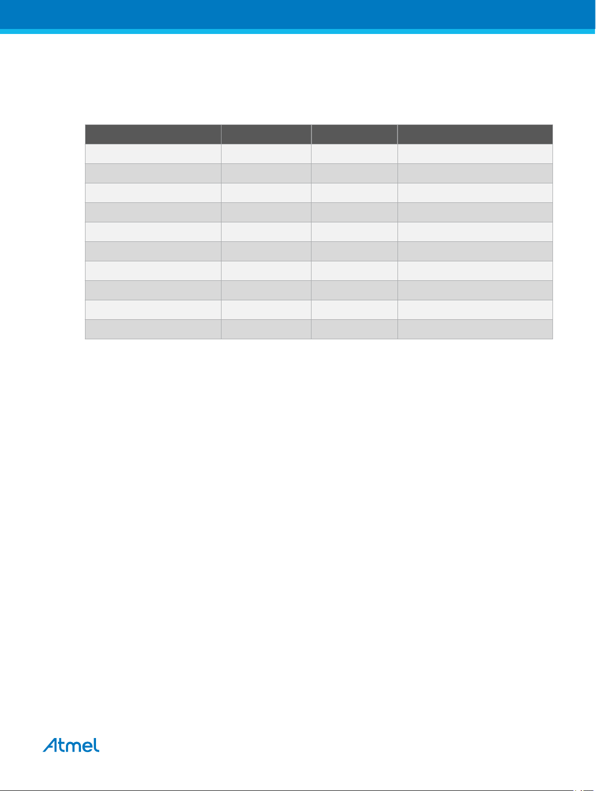
Table 4-10. Atmel-ICE JTAG Pin Description
Name AVR
port
pin
SAM
port
pin
Description
TCK 1 4 Test Clock (clock signal from the Atmel-ICE into the target device).
TMS 5 2 Test Mode Select (control signal from the Atmel-ICE into the target device).
TDI 9 8 Test Data In (data transmitted from the Atmel-ICE into the target device).
TDO 3 6 Test Data Out (data transmitted from the target device into the Atmel-ICE).
nTRST 8 - Test Reset (optional, only on some AVR devices). Used to reset the JTAG
TAP controller.
nSRST 6 10 Reset (optional). Used to reset the target device. Connecting this pin is
recommended since it allows the Atmel-ICE to hold the target device in a
reset state, which can be essential to debugging in certain scenarios.
Atmel Atmel-ICE [USER GUIDE]
Atmel-42330C-Atmel-ICE_User Guide-10/2016
37
Page 38

Name AVR
SAM
port
pin
VTG 4 1 Target voltage reference. The Atmel-ICE samples the target voltage on this
GND 2, 10 3, 5, 9 Ground. All must be connected to ensure that the Atmel-ICE and the target
4.4.3. SPI Physical Interface
In-System Programming uses the target Atmel AVR’s internal SPI (Serial Peripheral Interface) to
download code into the flash and EEPROM memories. It is not a debugging interface. When designing an
application PCB, which includes an AVR with the SPI interface, the pinout as shown in the figure below
should be used.
Figure 4-10. SPI Header Pinout
port
pin
Description
pin in order to power the level converters correctly. The Atmel-ICE draws
less than 3mA from this pin in debugWIRE mode and less than 1mA in
other modes.
device share the same ground reference.
SCK
1 2
VCC
PDI/MOSI
GND
SPI
PDO/MISO
/RESET
4.4.4. Connecting to an SPI Target
The recommended pinout for the 6-pin SPI connector is shown in Figure 4-10.
Connection to a 6-pin 100-mil SPI header
Use the 6-pin 100-mil tap on the flat cable (included in some kits) to connect to a standard 100-mil SPI
header.
Connection to a 6-pin 50-mil SPI header
Use the adapter board (included in some kits) to connect to a standard 50-mil SPI header.
Connection to a custom 100-mil header
The 10-pin mini-squid cable should be used to connect between the Atmel-ICE AVR connector port and
the target board. Six connections are required, as described in the table below.
Important:
The SPI interface is effectively disabled when the debugWIRE enable fuse (DWEN) is
programmed, even if SPIEN fuse is also programmed. To re-enable the SPI interface, the
'disable debugWIRE' command must be issued while in a debugWIRE debugging session.
Disabling debugWIRE in this manner requires that the SPIEN fuse is already programmed. If
Atmel Studio fails to disable debugWIRE, it is probable because the SPIEN fuse is NOT
programmed. If this is the case, it is necessary to use a high-voltage programming interface to
program the SPIEN fuse.
Atmel Atmel-ICE [USER GUIDE]
Atmel-42330C-Atmel-ICE_User Guide-10/2016
38
Page 39

Info:
The SPI interface is often referred to as "ISP", since it was the first In System Programming
interface on Atmel AVR products. Other interfaces are now available for In System
Programming.
Table 4-11. Atmel-ICE SPI Pin Mapping
Atmel-ICE AVR port pins Target pins Mini-squid pin SPI pinout
Pin 1 (TCK) SCK 1 3
Pin 2 (GND) GND 2 6
Pin 3 (TDO) MISO 3 1
Pin 4 (VTG) VTG 4 2
Pin 5 (TMS) 5
Pin 6 (nSRST) /RESET 6 5
Pin 7 (not connected) 7
Pin 8 (nTRST) 8
Pin 9 (TDI) MOSI 9 4
Pin 10 (GND) 0
4.4.5. PDI
The Program and Debug Interface (PDI) is an Atmel proprietary interface for external programming and
on-chip debugging of a device. PDI Physical is a 2-pin interface providing a bi-directional half-duplex
synchronous communication with the target device.
When designing an application PCB, which includes an Atmel AVR with the PDI interface, the pinout
shown in the figure below should be used. One of the 6-pin adapters provided with the Atmel-ICE kit can
then be used to connect the Atmel-ICE probe to the application PCB.
Figure 4-11. PDI Header Pinout
4.4.6. Connecting to a PDI Target
The recommended pinout for the 6-pin PDI connector is shown in Figure 4-11.
Connection to a 6-pin 100-mil PDI header
Use the 6-pin 100-mil tap on the flat cable (included in some kits) to connect to a standard 100-mil PDI
header.
PDI_DATA
(NC)
PDI_CLK
1 2
VCC
(NC)
GND
PDI
Connection to a 6-pin 50-mil PDI header
Use the adapter board (included in some kits) to connect to a standard 50-mil PDI header.
Connection to a custom 100-mil header
Atmel Atmel-ICE [USER GUIDE]
Atmel-42330C-Atmel-ICE_User Guide-10/2016
39
Page 40

The 10-pin mini-squid cable should be used to connect between the Atmel-ICE AVR connector port and
the target board. Four connections are required, as described in the table below.
Important:
The pinout required is different from the JTAGICE mkII JTAG probe, where PDI_DATA is
connected to pin 9. The Atmel-ICE is compatible with the pinout used by the Atmel-ICE,
JTAGICE3, AVR ONE!, and AVR Dragon™ products.
Table 4-12. Atmel-ICE PDI Pin Mapping
Atmel-ICE AVR port pin Target pins Mini-squid pin Atmel STK600 PDI pinout
Pin 1 (TCK) 1
Pin 2 (GND) GND 2 6
Pin 3 (TDO) PDI_DATA 3 1
Pin 4 (VTG) VTG 4 2
Pin 5 (TMS) 5
Pin 6 (nSRST) PDI_CLK 6 5
Pin 7 (not connected) 7
Pin 8 (nTRST) 8
Pin 9 (TDI) 9
Pin 10 (GND) 0
4.4.7. UPDI Physical Interface
The Unified Program and Debug Interface (UPDI) is an Atmel proprietary interface for external
programming and on-chip debugging of a device. It is a successor to the PDI 2-wire physical interface,
which is found on all AVR XMEGA devices. UPDI is a single-wire interface providing a bi-directional halfduplex asynchronous communication with the target device for purposes of programming and debugging.
When designing an application PCB, which includes an Atmel AVR with the UPDI interface, the pinout
shown below should be used. One of the 6-pin adapters provided with the Atmel-ICE kit can then be used
to connect the Atmel-ICE probe to the application PCB.
Figure 4-12. UPDI Header Pinout
4.4.7.1. UPDI and /RESET
The UPDI one-wire interface can be a dedicated pin or a shared pin, depending on the target AVR device.
Consult the device datasheet for further information.
Atmel Atmel-ICE [USER GUIDE]
Atmel-42330C-Atmel-ICE_User Guide-10/2016
40
Page 41

When the UPDI interface is on a shared pin, the pin can be configured to be either UPDI, /RESET, or
GPIO by setting the RSTPINCFG[1:0] fuses.
The RSTPINCFG[1:0] fuses have the following configurations, as described in the datasheet. The
practical implications of each choice are given here.
Table 4-13. RSTPINCFG[1:0] Fuse Configuration
RSTPINCFG[1:0] Configuration Usage
00 GPIO General purpose I/O pin. In order to access UPDI, a 12V pulse must
be applied to this pin. No external reset source is available.
01 UPDI Dedicated programming and debugging pin. No external reset
source is available.
10 Reset Reset signal input. In order to access UPDI, a 12V pulse must be
applied to this pin.
11 Reserved NA
Note: Older AVR devices have a programming interface, known as "High-Voltage Programming" (both
serial and parallel variants exist.) In general this interface requires 12V to be applied to the /RESET pin
for the duration of the programming session. The UPDI interface is an entirely different interface. The
UPDI pin is primarily a programming and debugging pin, which can be fused to have an alternative
function (/RESET or GPIO). If the alternative function is selected then a 12V pulse is required on that pin
in order to re-activate the UPDI functionality.
Note: If a design requires the sharing of the UPDI signal due to pin constraints, steps must be taken in
order to ensure that the device can be programmed. To ensure that the UPDI signal can function
correctly, as well as to avoid damage to external components from the 12V pulse, it is recommended to
disconnect any components on this pin when attempting to debug or program the device. This can be
done using a 0Ω resistor, which is mounted by default and removed or replaced by a pin header while
debugging. This configuration effectively means that programming should be done before mounting the
device.
Important: The Atmel-ICE does not support 12V on the UPDI line. In other words, if the UPDI
pin has been configured as GPIO or RESET the Atmel-ICE will not be able to enable the UPDI
interface.
4.4.8. Connecting to a UPDI Target
The recommended pinout for the 6-pin UPDI connector is shown in Figure 4-12.
Connection to a 6-pin 100-mil UPDI header
Use the 6-pin 100-mil tap on the flat cable (included in some kits) to connect to a standard 100-mil UPDI
header.
Connection to a 6-pin 50-mil UPDI header
Use the adapter board (included in some kits) to connect to a standard 50-mil UPDI header.
Connection to a custom 100-mil header
The 10-pin mini-squid cable should be used to connect between the Atmel-ICE AVR connector port and
the target board. Three connections are required, as described in the table below.
Atmel Atmel-ICE [USER GUIDE]
Atmel-42330C-Atmel-ICE_User Guide-10/2016
41
Page 42

Table 4-14. Atmel-ICE UPDI Pin Mapping
Atmel-ICE AVR port pin Target pins Mini-squid pin Atmel STK600 UPDI pinout
Pin 1 (TCK) 1
Pin 2 (GND) GND 2 6
Pin 3 (TDO) UPDI_DATA 3 1
Pin 4 (VTG) VTG 4 2
Pin 5 (TMS) 5
Pin 6 (nSRST) [/RESET sense] 6 5
Pin 7 (Not connected) 7
Pin 8 (nTRST) 8
Pin 9 (TDI) 9
Pin 10 (GND) 0
4.4.9. TPI Physical Interface
TPI is a programming-only interface for some AVR ATtiny devices. It is not a debugging interface, and
these devices do not have OCD capability. When designing an application PCB which includes an AVR
with the TPI interface, the pinout shown in the figure below should be used.
Figure 4-13. TPI Header Pinout
4.4.10. Connecting to a TPI Target
The recommended pinout for the 6-pin TPI connector is shown in Figure 4-13.
Connection to a 6-pin 100-mil TPI header
Use the 6-pin 100-mil tap on the flat cable (included in some kits) to connect to a standard 100-mil TPI
header.
Connection to a 6-pin 50-mil TPI header
Use the adapter board (included in some kits) to connect to a standard 50-mil TPI header.
Connection to a custom 100-mil header
The 10-pin mini-squid cable should be used to connect between the Atmel-ICE AVR connector port and
the target board. Six connections are required, as described in the table below.
Table 4-15. Atmel-ICE TPI Pin Mapping
Atmel-ICE AVR port pins Target pins Mini-squid pin TPI pinout
TPIDATA
TPICLK
/RESET
1 2
VCC
(NC)
GND
TPI
Pin 1 (TCK) CLOCK 1 3
Pin 2 (GND) GND 2 6
Pin 3 (TDO) DATA 3 1
Atmel Atmel-ICE [USER GUIDE]
Atmel-42330C-Atmel-ICE_User Guide-10/2016
42
Page 43

Atmel-ICE AVR port pins Target pins Mini-squid pin TPI pinout
Pin 4 (VTG) VTG 4 2
Pin 5 (TMS) 5
Pin 6 (nSRST) /RESET 6 5
Pin 7 (not connected) 7
Pin 8 (nTRST) 8
Pin 9 (TDI) 9
Pin 10 (GND) 0
4.4.11. Advanced Debugging (AVR JTAG /debugWIRE devices)
I/O Peripherals
Most I/O peripherals will continue to run even though the program execution is stopped by a breakpoint.
Example: If a breakpoint is reached during a UART transmission, the transmission will be completed and
corresponding bits set. The TXC (transmit complete) flag will be set and be available on the next single
step of the code even though it normally would happen later in an actual device.
All I/O modules will continue to run in stopped mode with the following two exceptions:
• Timer/Counters (configurable using the software front-end)
• Watchdog Timer (always stopped to prevent resets during debugging)
Single Stepping I/O access
Since the I/O continues to run in stopped mode, care should be taken to avoid certain timing issues. For
example, the code:
OUT PORTB, 0xAA
IN TEMP, PINB
When running this code normally, the TEMP register would not read back 0xAA because the data would
not yet have been latched physically to the pin by the time it is sampled by the IN operation. A NOP
instruction must be placed between the OUT and the IN instruction to ensure that the correct value is
present in the PIN register.
However, when single stepping this function through the OCD, this code will always give 0xAA in the PIN
register since the I/O is running at full speed even when the core is stopped during the single stepping.
Single stepping and timing
Certain registers need to be read or written within a given number of cycles after enabling a control
signal. Since the I/O clock and peripherals continue to run at full speed in stopped mode, single stepping
through such code will not meet the timing requirements. Between two single steps, the I/O clock may
have run millions of cycles. To successfully read or write registers with such timing requirements, the
whole read or write sequence should be performed as an atomic operation running the device at full
speed. This can be done by using a macro or a function call to execute the code, or use the run-to-cursor
function in the debugging environment.
Atmel Atmel-ICE [USER GUIDE]
Atmel-42330C-Atmel-ICE_User Guide-10/2016
43
Page 44

Accessing 16-bit registers
The Atmel AVR peripherals typically contain several 16-bit registers that can be accessed via the 8-bit
data bus (e.g.: TCNTn of a 16-bit timer). The 16-bit register must be byte accessed using two read or
write operations. Breaking in the middle of a 16-bit access or single stepping through this situation may
result in erroneous values.
Restricted I/O register access
Certain registers cannot be read without affecting their contents. Such registers include those which
contain flags which are cleared by reading, or buffered data registers (e.g.: UDR). The software front-end
will prevent reading these registers when in stopped mode to preserve the intended non-intrusive nature
of OCD debugging. In addition, some registers cannot safely be written without side-effects occurring these registers are read-only. For example:
• Flag registers, where a flag is cleared by writing '1' to any bit. These registers are read-only.
• UDR and SPDR registers cannot be read without affecting the state of the module. These registers
are not accessible.
4.4.12. megaAVR Special Considerations
Software breakpoints
Since it contains an early version of the OCD module, ATmega128[A] does not support the use of the
BREAK instruction for software breakpoints.
JTAG clock
The target clock frequency must be accurately specified in the software front-end before starting a debug
session. For synchronization reasons, the JTAG TCK signal must be less than one fourth of the target
clock frequency for reliable debugging. When programming via the JTAG interface, the TCK frequency is
limited by the maximum frequency rating of the target device, and not the actual clock frequency being
used.
When using the internal RC oscillator, be aware that the frequency may vary from device to device and is
affected by temperature and VCC changes. Be conservative when specifying the target clock frequency.
JTAGEN and OCDEN fuses
The JTAG interface is enabled using the JTAGEN fuse, which is programmed by default. This allows
access to the JTAG programming interface. Through this mechanism, the OCDEN fuse can be
programmed (by default OCDEN is un-programmed). This allows access to the OCD in order to facilitate
debugging the device. The software front-end will always ensure that the OCDEN fuse is left unprogrammed when terminating a session, thereby restricting unnecessary power consumption by the
OCD module. If the JTAGEN fuse is unintentionally disabled, it can only be re-enabled using SPI or High
Voltage programming methods.
If the JTAGEN fuse is programmed, the JTAG interface can still be disabled in firmware by setting the
JTD bit. This will render code un-debuggable, and should not be done when attempting a debug session.
If such code is already executing on the Atmel AVR device when starting a debug session, the Atmel-ICE
will assert the RESET line while connecting. If this line is wired correctly, it will force the target AVR device
into reset, thereby allowing a JTAG connection.
If the JTAG interface is enabled, the JTAG pins cannot be used for alternative pin functions. They will
remain dedicated JTAG pins until either the JTAG interface is disabled by setting the JTD bit from the
program code, or by clearing the JTAGEN fuse through a programming interface.
Atmel Atmel-ICE [USER GUIDE]
Atmel-42330C-Atmel-ICE_User Guide-10/2016
44
Page 45

Tip:
Be sure to check the "use external reset" checkbox in both the programming dialog and debug
options dialog in order to allow the Atmel-ICE to assert the RESET line and re-enable the JTAG
interface on devices which are running code which disables the JTAG interface by setting the
JTD bit.
IDR/OCDR events
The IDR (In-out Data Register) is also known as the OCDR (On Chip Debug Register), and is used
extensively by the debugger to read and write information to the MCU when in stopped mode during a
debug session. When the application program in run mode writes a byte of data to the OCDR register of
the AVR device being debugged, the Atmel-ICE reads this value out and displays it in the message
window of the software front-end. The OCDR register is polled every 50ms, so writing to it at a higher
frequency will NOT yield reliable results. When the AVR device loses power while it is being debugged,
spurious OCDR events may be reported. This happens because the Atmel-ICE may still poll the device
as the target voltage drops below the AVR’s minimum operating voltage.
4.4.13. AVR XMEGA Special Considerations
OCD and clocking
When the MCU enters stopped mode, the OCD clock is used as MCU clock. The OCD clock is either the
JTAG TCK if the JTAG interface is being used, or the PDI_CLK if the PDI interface is being used.
I/O modules in stopped mode
In contrast to earlier Atmel megaAVR devices, in XMEGA the I/O modules are stopped in stop mode. This
means that USART transmissions will be interrupted, timers (and PWM) will be stopped.
Hardware breakpoints
There are four hardware breakpoint comparators - two address comparators and two value comparators.
They have certain restrictions:
• All breakpoints must be of the same type (program or data)
• All data breakpoints must be in the same memory area (I/O, SRAM, or XRAM)
• There can only be one breakpoint if address range is used
Here are the different combinations that can be set:
• Two single data or program address breakpoints
• One data or program address range breakpoint
• Two single data address breakpoints with single value compare
• One data breakpoint with address range, value range, or both
Atmel Studio will tell you if the breakpoint can't be set, and why. Data breakpoints have priority over
program breakpoints, if software breakpoints are available.
External reset and PDI physical
The PDI physical interface uses the reset line as clock. While debugging, the reset pullup should be 10k
or more or be removed. Any reset capacitors should be removed. Other external reset sources should be
disconnected.
Atmel Atmel-ICE [USER GUIDE]
Atmel-42330C-Atmel-ICE_User Guide-10/2016
45
Page 46

Debugging with sleep for ATxmegaA1 rev H and earlier
A bug existed on early versions of ATxmegaA1 devices that prevented the OCD from being enabled while
the device was in certain sleep modes. There are two workarounds to re-enable OCD:
• Go into the Atmel-ICE. Options in the Tools menu and enable "Always activate external reset when
reprogramming device".
• Perform a chip erase
The sleep modes that trigger this bug are:
• Power-down
• Power-save
• Standby
• Extended standby
4.4.14. debugWIRE Special Considerations
The debugWIRE communication pin (dW) is physically located on the same pin as the external reset
(RESET). An external reset source is therefore not supported when the debugWIRE interface is enabled.
The debugWIRE Enable fuse (DWEN) must be set on the target device in order for the debugWIRE
interface to function. This fuse is by default un-programmed when the Atmel AVR device is shipped from
the factory. The debugWIRE interface itself cannot be used to set this fuse. In order to set the DWEN
fuse, the SPI mode must be used. The software front-end handles this automatically provided that the
necessary SPI pins are connected. It can also be set using SPI programming from the Atmel Studio
programming dialog.
Either: Attempt to start a debug session on the debugWIRE part. If the debugWIRE interface is not
enabled, Atmel Studio will offer to retry, or attempt to enable debugWIRE using SPI
programming. If you have the full SPI header connected, debugWIRE will be enabled, and you
will be asked to toggle power on the target. This is required for the fuse changes to be effective.
Or: Open the programming dialog in SPI mode, and verify that the signature matches the correct
device. Check the DWEN fuse to enable debugWIRE.
Important:
It is important to leave the SPIEN fuse programmed, the RSTDISBL fuse un-programmed! Not
doing this will render the device stuck in debugWIRE mode, and High Voltage programming will
be required to revert the DWEN setting.
To disable the debugWIRE interface, use High Voltage programming to un-program the DWEN fuse.
Alternately, use the debugWIRE interface itself to temporarily disable itself, which will allow SPI
programming to take place, provided that the SPIEN fuse is set.
Important:
If the SPIEN fuse was NOT left programmed, Atmel Studio will not be able to complete this
operation, and High Voltage programming must be used.
Atmel Atmel-ICE [USER GUIDE]
Atmel-42330C-Atmel-ICE_User Guide-10/2016
46
Page 47

During a debug session, select the 'Disable debugWIRE and Close' menu option from the 'Debug' menu.
DebugWIRE will be temporarily disabled, and Atmel Studio will use SPI programming to un-program the
DWEN fuse.
Having the DWEN fuse programmed enables some parts of the clock system to be running in all sleep
modes. This will increase the power consumption of the AVR while in sleep modes. The DWEN Fuse
should therefore always be disabled when debugWIRE is not used.
When designing a target application PCB where debugWIRE will be used, the following considerations
must be made for correct operation:
• Pull-up resistors on the dW/(RESET) line must not be smaller (stronger) than 10kΩ. The pull-up
resistor is not required for debugWIRE functionality, since the debugger tool provides this.
• Any stabilizing capacitor connected to the RESET pin must be disconnected when using
debugWIRE, since they will interfere with correct operation of the interface
• All external reset sources or other active drivers on the RESET line must be disconnected, since
they may interfere with the correct operation of the interface
Never program the lock-bits on the target device. The debugWIRE interface requires that lock-bits are
cleared in order to function correctly.
4.4.15. debugWIRE Software Breakpoints
The debugWIRE OCD is drastically scaled down when compared to the Atmel megaAVR (JTAG) OCD.
This means that it does not have any program counter breakpoint comparators available to the user for
debugging purposes. One such comparator does exist for purposes of run-to-cursor and single-stepping
operations, but additional user breakpoints are not supported in hardware.
Instead, the debugger must make use of the AVR BREAK instruction. This instruction can be placed in
FLASH, and when it is loaded for execution it will cause the AVR CPU to enter stopped mode. To support
breakpoints during debugging, the debugger must insert a BREAK instruction into FLASH at the point at
which the users requests a breakpoint. The original instruction must be cached for later replacement.
When single stepping over a BREAK instruction, the debugger has to execute the original cached
instruction in order to preserve program behavior. In extreme cases, the BREAK has to be removed from
FLASH and replaced later. All these scenarios can cause apparent delays when single stepping from
breakpoints, which will be exacerbated when the target clock frequency is very low.
It is thus recommended to observe the following guidelines, where possible:
• Always run the target at as high a frequency as possible during debugging. The debugWIRE
physical interface is clocked from the target clock.
• Try to minimize on the number of breakpoint additions and removals, as each one require a FLASH
page to be replaced on the target
• Try to add or remove a small number of breakpoints at a time, to minimize the number of FLASH
page write operations
• If possible, avoid placing breakpoints on double-word instructions
4.4.16. Understanding debugWIRE and the DWEN Fuse
When enabled, the debugWIRE interface takes control of the device's /RESET pin, which makes it
mutually exclusive to the SPI interface, which also needs this pin. When enabling and disabling the
debugWIRE module, follow one of these two approaches:
• Let Atmel Studio take care of things (recommended)
• Set and clear DWEN manually (exercise caution, advanced users only!)
Atmel Atmel-ICE [USER GUIDE]
Atmel-42330C-Atmel-ICE_User Guide-10/2016
47
Page 48

Important: When manipulating DWEN manually, it is important that the SPIEN fuse remains
Atmel Studio
start debug session
Power toggle
(latches debugWIRE state)
Studio "Disable debugWIRE and close"
(disables debugWIRE module temporarily
and then clears DWEN fuse using SPI)
atprogram dwdisable
(atprogram disables
debugWIRE module temporarily)
Clear DWEN fuse
using SPI
Set DWEN fuse
using SPI
Intermediate state 1:
Fuse DWEN set
Fuse SPIEN set* (NB!)
Module debugWIRE disabled until power toggle
You can: Toggle power
DWEN
SPIEN
Default state:
Fuse DWEN cleared
Fuse SPIEN set
Module debugWIRE disabled
You can: Access flash and fuses using SPI
DWEN
SPIEN
Debug state:
Fuse DWEN set
Fuse SPIEN set
Module debugWIRE enabled
You can: use debugWIRE
You cannot: Access fuses or flash using SPI
DWEN
SPIEN
Intermediate state 2:
Fuse DWEN set
Fuse SPIEN set
Module debugWIRE disabled
You can: Access fuses and flash using SPI
DWEN
SPIEN
Debug state (not recommended):
Fuse DWEN set
Fuse SPIEN cleared
Module debugWIRE enabled
You can: use debugWIRE
To access flash and fuses it is now necessary to
use the High-Voltage Programming interface
DWEN
SPIEN
set to avoid having to use High-Voltage programming.
Figure 4-14. Understanding debugWIRE and the DWEN Fuse
4.4.17. TinyX-OCD (UPDI) Special Considerations
The UPDI data pin (UPDI_DATA) can be a dedicated pin or a shared pin, depending on the target AVR
device. A shared UPDI pin is 12V tolerant, and can be configured to be used as /RESET or GPIO. For
further details on how to use the pin in these configurations, see UPDI Physical Interface.
On devices which include the CRCSCAN module (Cyclic Redundancy Check Memory Scan) this module
should not be used in continuous background mode while debugging. The OCD module has limited
hardware breakpoint comparator resources, so BREAK instructions may be inserted into flash (software
breakpoints) when more breakpoints are required, or even during source-level code stepping. The CRC
module could incorrectly detect this breakpoint as a corruption of flash memory contents.
The CRCSCAN module can also be configured to perform a CRC scan before boot. In the case of a CRC
mismatch, the device will not boot, and appear to be in a locked state. The only way to recover the device
from this state is to perform a full chip erase and either program a valid flash image or disable the preboot CRCSCAN. (A simple chip erase will result in a blank flash with invalid CRC, and the part will thus
still not boot.) Atmel Studio will automatically disable the CRCSCAN fuses when chip erasing a device in
this state.
Atmel Atmel-ICE [USER GUIDE]
Atmel-42330C-Atmel-ICE_User Guide-10/2016
48
Page 49

When designing a target application PCB where UPDI interface will be used, the following considerations
must be made for correct operation:
• Pull-up resistors on the UPDI line must not be smaller (stronger) than 10kΩ. A pull-down resistor
should not be used, or it should be removed when using UPDI. The UPDI physical is push-pull
capable, so only a weak pull-up resistor is required to prevent false start bit triggering when the line
is idle.
• If the UPDI pin is to be used as a RESET pin, any stabilizing capacitor must be disconnected when
using UPDI, since it will interfere with correct operation of the interface
• If the UPDI pin is used as RESET or GPIO pin, all external drivers on the line must be disconnected
during programming or debugging since they may interfere with the correct operation of the
interface
Atmel Atmel-ICE [USER GUIDE]
Atmel-42330C-Atmel-ICE_User Guide-10/2016
49
Page 50

5. Hardware Description
5.1. LEDs
The Atmel-ICE top panel has three LEDs which indicate the status of current debug or programming
sessions.
Table 5-1. LEDs
LED Function Description
Left Target power GREEN when target power is OK. Flashing indicates a target power
Middle Main power RED when main-board power is OK.
Right Status Flashing GREEN when the target is running/stepping. OFF when
5.2. Rear Panel
The rear panel of the Atmel-ICE houses the Micro-B USB connector.
error. Does not light up until a programming/debugging session
connection is started.
target is stopped.
Atmel Atmel-ICE [USER GUIDE]
Atmel-42330C-Atmel-ICE_User Guide-10/2016
50
Page 51

5.3. Bottom Panel
The bottom panel of the Atmel-ICE has a sticker which shows the serial number and date of manufacture.
When seeking technical support, include these details.
5.4. Architecture Description
The Atmel-ICE architecture is shown in the block diagram in Figure 5-1.
Figure 5-1. Atmel-ICE Block Diagram
host
PC
5.4.1. Atmel-ICE Main Board
Power is supplied to the Atmel-ICE from the USB bus, regulated to 3.3V by a step-down switch-mode
regulator. The VTG pin is used as a reference input only, and a separate power supply feeds the variable-
USB
power
supply
buffer
UC3A4
MCU
level
conversion
AVR
Atmel
target
device
SAM
filters &
protection
Atmel Atmel-ICE [USER GUIDE]
Atmel-42330C-Atmel-ICE_User Guide-10/2016
51
Page 52

voltage side of the on-board level converters. At the heart of the Atmel-ICE main board is the Atmel AVR
UC3 microcontroller AT32UC3A4256, which runs at between 1MHz and 60MHz depending on the tasks
being processed. The microcontroller includes an on-chip USB 2.0 high-speed module, allowing high data
throughput to and from the debugger.
Communication between the Atmel-ICE and the target device is done through a bank of level converters
that shift signals between the target's operating voltage and the internal voltage level on the Atmel-ICE.
Also in the signal path are zener overvoltage protection diodes, series termination resistors, inductive
filters and ESD protection diodes. All signal channels can be operated in the range 1.62V to 5.5V,
although the Atmel-ICE hardware can not drive out a higher voltage than 5.0V. Maximum operating
frequency varies according to the target interface in use.
5.4.2. Atmel-ICE Target Connectors
The Atmel-ICE don't have an active probe. A 50-mil IDC cable is used to connect to the target application
either directly, or through the adapters included in some kits. For more information on the cabling and
adapters, see section Assembling the Atmel-ICE
5.4.3. Atmel-ICE Target Connectors Part Numbers
In order to connect the Atmel-ICE 50-mil IDC cable directly to a target board, any standard 50-mil 10-pin
header should suffice. It is advised to use keyed headers to ensure correct orientation when connecting
to the target, such as those used on the adapter board included with the kit.
The part number for this header is: FTSH-105-01-L-DV-K-A-P from SAMTEC.
Atmel Atmel-ICE [USER GUIDE]
Atmel-42330C-Atmel-ICE_User Guide-10/2016
52
Page 53

6. Software Integration
6.1. Atmel Studio
6.1.1. Software Integration in Atmel Studio
Atmel Studio is an Integrated Development Environment (IDE) for writing and debugging Atmel AVR and
Atmel SAM applications in Windows environments. Atmel Studio provides a project management tool,
source file editor, simulator, assembler and front-end for C/C++, programming, emulation and on-chip
debugging.
Atmel Studio version 6.2 or later must be used in conjunction with the Atmel-ICE.
6.1.2. Programming Options
Atmel Studio supports programming of Atmel AVR and Atmel SAM ARM devices using the Atmel-ICE.
The programming dialog can be configured to use JTAG, aWire, SPI, PDI, TPI, SWD modes, according to
the target device selected.
When configuring the clock frequency, different rules apply for different interfaces and target families:
• SPI programming makes use of the target clock. Configure the clock frequency to be lower than
one fourth the frequency at which the target device is currently running.
• JTAG programming on Atmel megaAVR devices is clocked by the programmer. This means that the
programming clock frequency is limited to the maximum operating frequency of the device itself.
(Usually 16MHz.)
• AVR XMEGA programming on both JTAG and PDI interfaces is clocked by the programmer. This
means that the programming clock frequency is limited to the maximum operating frequency of the
device itself. (Usually 32MHz).
• AVR UC3 programming on JTAG interface is clocked by the programmer. This means that the
programming clock frequency is limited to the maximum operating frequency of the device itself.
(Limited to 33MHz.)
• AVR UC3 programming on aWire interface is clocked by the programmer. The optimal frequency is
given by the SAB bus speed in the target device. The Atmel-ICE debugger will automatically tune
the aWire baud rate to meet this criteria. Although it's usually not necessary the user can limit the
maximum baud rate if needed (e.g. in noisy environments).
• SAM device programming on SWD interface is clocked by the programmer. The maximum
frequency supported by Atmel-ICE is 2MHz. The frequency should not exceed the target CPU
frequency times 10,
f
SWD
≤ 10f
SYSCLK
.
6.1.3. Debug Options
When debugging an Atmel AVR device using Atmel Studio, the 'Tool' tab in the project properties view
contains some important configuration options. The options which need further explanation are detailed
here.
Target Clock Frequency
Accurately setting the target clock frequency is vital to achieve reliable debugging of Atmel megaAVR
device over the JTAG interface. This setting should be less than one fourth of the lowest operating
frequency of your AVR target device in the application being debugged. See megaAVR Special
Considerations for more information.
Atmel Atmel-ICE [USER GUIDE]
Atmel-42330C-Atmel-ICE_User Guide-10/2016
53
Page 54

Debug sessions on debugWIRE target devices are clocked by the target device itself, and thus no
frequency setting is required. The Atmel-ICE will automatically select the correct baud rate for
communicating at the start of a debug session. However, if you are experiencing reliability problems
related to a noisy debug environment, some tools offer the possibility to force the debugWIRE speed to a
fraction of its "recommended" setting.
Debug sessions on AVR XMEGA target devices can be clocked at up to the maximum speed of the
device itself (usually 32MHz).
Debug sessions on AVR UC3 target devices over the JTAG interface can be clocked at up to the
maximum speed of the device itself (limited to 33MHz). However, the optimal frequency will be slightly
below the current SAB clock on the target device.
Debug sessions on UC3 target devices over the aWire interface will be automatically tuned to the optimal
baud rate by the Atmel-ICE itself. However, if you are experiencing reliability problems related to a noisy
debug environment, some tools offer the possibility to force the aWire speed below a configurable limit.
Debug sessions on SAM target devices over the SWD interface can be clocked at up to ten times the
CPU clock (but limited to 2MHz max.)
Preserve EEPROM
Select this option to avoid erasing the EEPROM during reprogramming of the target before a debug
session.
Use external reset
If your target application disables the JTAG interface, the external reset must be pulled low during
programming. Selecting this option avoids repeatedly being asked whether to use the external reset.
6.2. Command Line Utility
Atmel Studio comes with a command line utility called atprogram that can be used to program targets
using the Atmel-ICE. During the Atmel Studio installation a shortcut called "Atmel Studio 7.0. Command
Prompt" were created in the Atmel folder on the Start menu. By double clicking this shortcut a command
prompt will be opened and programming commands can be entered. The command line utility is installed
in the Atmel Studio installation path in the folder Atmel/Atmel Studio 7.0/atbackend/.
To get more help on the command line utility type the command:
atprogram --help
Atmel Atmel-ICE [USER GUIDE]
Atmel-42330C-Atmel-ICE_User Guide-10/2016
54
Page 55

7. Advanced Debugging Techniques
7.1. Atmel AVR UC3 Targets
7.1.1. EVTI / EVTO Usage
The EVTI and EVTO pins are not accessible on the Atmel-ICE. However, they can still be used in
conjunction with other external equipment.
EVTI can be used for the following purposes:
• The target can be forced to stop execution in response to an external event. If the Event In Control
(EIC) bits in the DC register are written to 0b01, high-to-low transition on the EVTI pin will generate
a breakpoint condition. EVTI must remain low for one CPU clock cycle to guarantee that a
breakpoint is triggered. The External Breakpoint bit (EXB) in DS is set when this occurs.
• Generating trace synchronization messages. Not used by the Atmel-ICE.
EVTO can be used for the following purposes:
Indicating that the CPU has entered debug mode. Setting the EOS bits in DC to 0b01 causes the
•
EVTO pin to be pulled low for one CPU clock cycle when the target device enters debug mode.
This signal can be used as a trigger source for an external oscilloscope.
• Indicating that the CPU has reached a breakpoint or watchpoint. By setting the EOC bit in a
corresponding Breakpoint/Watchpoint Control Register, the breakpoint or watchpoint status is
indicated on the EVTO pin. The EOS bits in DC must be set to 0xb10 to enable this feature. The
EVTO pin can then be connected to an external oscilloscope in order to examine watchpoint timing.
• Generating trace timing signals. Not used by the Atmel-ICE.
7.2. debugWIRE Targets
7.2.1. debugWIRE Software Breakpoints
The debugWIRE OCD is drastically scaled down when compared to the Atmel megaAVR (JTAG) OCD.
This means that it does not have any program counter breakpoint comparators available to the user for
debugging purposes. One such comparator does exist for purposes of run-to-cursor and single-stepping
operations, but additional user breakpoints are not supported in hardware.
Instead, the debugger must make use of the AVR BREAK instruction. This instruction can be placed in
FLASH, and when it is loaded for execution it will cause the AVR CPU to enter stopped mode. To support
breakpoints during debugging, the debugger must insert a BREAK instruction into FLASH at the point at
which the users requests a breakpoint. The original instruction must be cached for later replacement.
When single stepping over a BREAK instruction, the debugger has to execute the original cached
instruction in order to preserve program behavior. In extreme cases, the BREAK has to be removed from
FLASH and replaced later. All these scenarios can cause apparent delays when single stepping from
breakpoints, which will be exacerbated when the target clock frequency is very low.
It is thus recommended to observe the following guidelines, where possible:
• Always run the target at as high a frequency as possible during debugging. The debugWIRE
physical interface is clocked from the target clock.
• Try to minimize on the number of breakpoint additions and removals, as each one require a FLASH
page to be replaced on the target
Atmel Atmel-ICE [USER GUIDE]
Atmel-42330C-Atmel-ICE_User Guide-10/2016
55
Page 56

• Try to add or remove a small number of breakpoints at a time, to minimize the number of FLASH
page write operations
• If possible, avoid placing breakpoints on double-word instructions
Atmel Atmel-ICE [USER GUIDE]
Atmel-42330C-Atmel-ICE_User Guide-10/2016
56
Page 57

8. Release History and Known issues
8.1. Firmware Release History
Table 8-1. Public Firmware Revisions
Firmware version (decimal) Date Relevant changes
1.36 29.09.2016 Added support for UPDI interface
1.28 27.05.2015 Added support for SPI and
1.22 03.10.2014 Added code profiling.
(tinyX devices)
Made USB endpoint size
configurable
USART DGI interfaces.
Improved SWD speed.
Minor bug fixes.
Fixed issue related to JTAG daisy
chains with more than 64
instruction bits.
1.13 08.04.2014 JTAG clock frequency fix.
1.09 12.02.2014 First release of Atmel-ICE.
8.2. Known Issues Concerning the Atmel-ICE
8.2.1. General
• The initial Atmel-ICE batches had a weak USB connector. A new revision has been made with a
new and more robust USB connector. As an interim solution epoxy glue has been applied to the
already produced units of the first version to improve the mechanical stability.
8.2.2. Atmel AVR XMEGA OCD Specific Issues
• For the ATxmegaA1 family, only revision G or later is supported
Fix for ARM reset extension.
Fixed target power led issue.
Fix for debugWIRE with long
SUT.
Fixed oscillator calibration
command.
Atmel Atmel-ICE [USER GUIDE]
Atmel-42330C-Atmel-ICE_User Guide-10/2016
57
Page 58

8.2.3. Atmel AVR - Device Specific Issues
• Cycling power on ATmega32U6 during a debug session may cause a loss of contact with the
device
Atmel Atmel-ICE [USER GUIDE]
Atmel-42330C-Atmel-ICE_User Guide-10/2016
58
Page 59

9. Product Compliance
9.1. RoHS and WEEE
The Atmel-ICE and all accessories are manufactured in accordance to both the RoHS Directive
(2002/95/EC) and the WEEE Directive (2002/96/EC).
9.2. CE and FCC
The Atmel-ICE unit has been tested in accordance to the essential requirements and other relevant
provisions of Directives:
• Directive 2004/108/EC (class B)
• FCC part 15 subpart B
• 2002/95/EC (RoHS, WEEE)
The following standards are used for evaluation:
• EN 61000-6-1 (2007)
• EN 61000-6-3 (2007) + A1(2011)
• FCC CFR 47 Part 15 (2013)
The Technical Construction File is located at:
Atmel Norway
Vestre Rosten 79
7075 Tiller
Norway
Every effort has been made to minimise electromagnetic emissions from this product. However, under
certain conditions, the system (this product connected to a target application circuit) may emit individual
electromagnetic component frequencies which exceed the maximum values allowed by the
abovementioned standards. The frequency and magnitude of the emissions will be determined by several
factors, including layout and routing of the target application with which the product is used.
Atmel Atmel-ICE [USER GUIDE]
Atmel-42330C-Atmel-ICE_User Guide-10/2016
59
Page 60

10. Revision History
Doc. Rev. Date Comments
42330C 10/2016 Added UPDI interface and updated Firmware Release History
42330B 03/2016 • Revised On-Chip Debugging chapter
42330A 06/2014 Initial document release
• New formatting of firmware release history in Release History
and Known issues chapter
• Added debug cable pinout
Atmel Atmel-ICE [USER GUIDE]
Atmel-42330C-Atmel-ICE_User Guide-10/2016
60
Page 61

Atmel Corporation 1600 Technology Drive, San Jose, CA 95110 USA T: (+1)(408) 441.0311 F: (+1)(408) 436.4200 | www.atmel.com
©
2016 Atmel Corporation. / Rev.: Atmel-42330C-Atmel-ICE_User Guide-10/2016
Atmel®, Atmel logo and combinations thereof, Enabling Unlimited Possibilities®, AVR®, megaAVR®, STK®, tinyAVR®, XMEGA®, and others are registered trademarks
or trademarks of Atmel Corporation in U.S. and other countries. ARM®, ARM Connected® logo, Cortex®, and others are the registered trademarks or trademarks of
ARM Ltd. Windows® is a registered trademark of Microsoft Corporation in U.S. and or other countries. Other terms and product names may be trademarks of others.
DISCLAIMER: The information in this document is provided in connection with Atmel products. No license, express or implied, by estoppel or otherwise, to any
intellectual property right is granted by this document or in connection with the sale of Atmel products. EXCEPT AS SET FORTH IN THE ATMEL TERMS AND
CONDITIONS OF SALES LOCATED ON THE ATMEL WEBSITE, ATMEL ASSUMES NO LIABILITY WHATSOEVER AND DISCLAIMS ANY EXPRESS, IMPLIED
OR STATUTORY WARRANTY RELATING TO ITS PRODUCTS INCLUDING, BUT NOT LIMITED TO, THE IMPLIED WARRANTY OF MERCHANTABILITY,
FITNESS FOR A PARTICULAR PURPOSE, OR NON-INFRINGEMENT. IN NO EVENT SHALL ATMEL BE LIABLE FOR ANY DIRECT, INDIRECT,
CONSEQUENTIAL, PUNITIVE, SPECIAL OR INCIDENTAL DAMAGES (INCLUDING, WITHOUT LIMITATION, DAMAGES FOR LOSS AND PROFITS, BUSINESS
INTERRUPTION, OR LOSS OF INFORMATION) ARISING OUT OF THE USE OR INABILITY TO USE THIS DOCUMENT, EVEN IF ATMEL HAS BEEN ADVISED
OF THE POSSIBILITY OF SUCH DAMAGES. Atmel makes no representations or warranties with respect to the accuracy or completeness of the contents of this
document and reserves the right to make changes to specifications and products descriptions at any time without notice. Atmel does not make any commitment to
update the information contained herein. Unless specifically provided otherwise, Atmel products are not suitable for, and shall not be used in, automotive
applications. Atmel products are not intended, authorized, or warranted for use as components in applications intended to support or sustain life.
SAFETY-CRITICAL, MILITARY, AND AUTOMOTIVE APPLICATIONS DISCLAIMER: Atmel products are not designed for and will not be used in connection with any
applications where the failure of such products would reasonably be expected to result in significant personal injury or death (“Safety-Critical Applications”) without
an Atmel officer's specific written consent. Safety-Critical Applications include, without limitation, life support devices and systems, equipment or systems for the
operation of nuclear facilities and weapons systems. Atmel products are not designed nor intended for use in military or aerospace applications or environments
unless specifically designated by Atmel as military-grade. Atmel products are not designed nor intended for use in automotive applications unless specifically
designated by Atmel as automotive-grade.
Page 62

Mouser Electronics
Authorized Distributor
Click to View Pricing, Inventory, Delivery & Lifecycle Information:
Microchip:
ATATMEL-ICE ATATMEL-ICE-ADPT ATATMEL-ICE-PCBA ATATMEL-ICE-CABLE ATATMEL-ICE-BASIC
 Loading...