


AT91SAM7S-EK Evaluation Board
..............................................................................................
User Guide


Table of Contents
Section 1
Overview...............................................................................................1-1
1.1 Scope........................................................................................................1-1
1.2 Deliverables ..............................................................................................1-1
1.3 AT91SAM7S-EK Evaluation Board ...........................................................1-1
Section 2
Setting Up the AT91SAM7S-EK Board................................................. 2-1
2.1 Electrostatic Warning ................................................................................2-1
2.2 Requirements............................................................................................2-1
2.3 Powering Up the Board .............................................................................2-1
2.4 Getting Started..........................................................................................2-1
2.5 AT91SAM7S-EK Block Diagram ...............................................................2-2
Section 3
Board Description ................................................................................. 3-1
3.1 AT91SAM7S256 Microcontroller...............................................................3-1
3.2 AT91SAM7S256 Block Diagram ...............................................................3-3
3.3 Memory .....................................................................................................3-3
3.4 Clock Circuitry...........................................................................................3-3
3.5 Reset Circuitry...........................................................................................3-4
3.6 Power Supply Circuitry..............................................................................3-4
3.7 Remote Communication............................................................................3-4
3.8 Analog Interface........................................................................................3-4
3.9 User Interface ...........................................................................................3-4
3.10 Debug Interface ........................................................................................3-4
3.11 Expansion Connector................................................................................3-4
3.12 Wrapping User Area..................................................................................3-4
Section 4
Configuration Straps ............................................................................. 4-1
4.1 Configuration Strap ...................................................................................4-1
Section 5
Schematics ........................................................................................... 5-1
5.1 Schematics ...............................................................................................5-1
Section 6
Revision History....................................................................................6-1
6.1 Revision History ........................................................................................6-1
AT91SAM7S-EK Evaluation Board User Guide i
6112C–ATARM–01-Feb-07

Table of Contents
ii AT91SAM7S-EK Evaluation Board User Guide
6112C–ATARM–01-Feb-07

Section 1
Overview
1.1 Scope The AT91SAM7S-EK evaluation board enables the evaluation of and code development
for applications running on an AT91SAM7Sxx device.
This document describes the evaluation board fitted with an AT91SAM7S256.
This guide focuses on the AT91SAM7S-EK board as an evaluation platform for the
AT91SAM7S family.
1.2 Deliverables
1.2.1 Standard Version AT91SAM7S-EK VAR
1.3 AT91SAM7S-EK Evaluation Board
The AT91SAM7S-EK package contains the following items:
! An AT91SAM7S-EK board
! One A/B-type USB cable
! One DVD-ROM containing summary and full datasheets, datasheets with electrical
and mechanical characteristics, application notes and getting started documents for
all development boards and AT91 microcontrollers. An AT91 software package with C
and assembly listings is also provided. This allows the user to begin evaluating the
AT91 ARM
The board is generally equipped with an AT91SAM7S256 (64-pin PQFP package)
together with the following:
! USB device port interface
! Two serial communication ports
! JTAG/ICE debug interface
! Four buffered analog inputs
! Four general-purpose LEDs and pushbuttons
! Expansion connector
®
Thumb® 32-bit microcontroller quickly.
! Prototyping area
AT91SAM7S-EK Evaluation Board User Guide 1-1
6112C–ATARM–01-Feb-07

Overview
Note: The user can also evaluate the AT91SAM7S32 with this board. A 48-pin TQFP
footprint has been provided for this purpose. To do so, the user must unsolder
the AT91SAM7S256 microcontroller (IC4) and fit the AT91SAM7S32 on the 48pin TQFP footprint (IC5).
1-2 AT91SAM7S-EK Evaluation Board User Guide
6112C–ATARM–01-Feb-07

Section 2
Setting Up the AT91SAM7S-EK
Board
2.1 Electrostatic Warning
The AT91SAM7S-EK evaluation board is shipped in protective anti-static packaging.
The board must not be subjected to high electrostatic potentials. A grounding strap or
similar protective device should be worn when handling the board. Avoid touching the
component pins or any other metallic element.
2.2 Requirements In order to set up the AT91SAM7S-EK evaluation board, the following items are needed:
! The AT91SAM7S-EK evaluation board itself.
! Optional DC power supply capable of supplying 7V to 12V at 0.5 A.
Note: The AT91SAM7S-EK is not delivered with the JTAG/ICE interface required to
start evaluating the device.
2.3 Powering Up the Board
AT91SAM7S-EK is self-powered by the USB port. If the USB port is not used, the card
can be supplied by an external DC power supply via the 2.1 mm socket (J1). The polarity of the power supply is not critical.
The regulator allows the input voltage range to be from 7V to 12V.
2.4 Getting Started The AT91SAM7S-EK evaluation board is delivered with a DVD-ROM containing all nec-
essary information and step-by-step procedures for working with the most common
development toolchains. Please refer to this DVD-ROM, or to the AT91 web site,
http://www.atmel.com/products/AT91/, for the most up-to-date information on getting
started with the AT91SAM7S-EK.
AT91SAM7S-EK Evaluation Board User Guide 2-1
6112C–ATARM–01-Feb-07
Setting Up the AT91SAM7S-EK Board
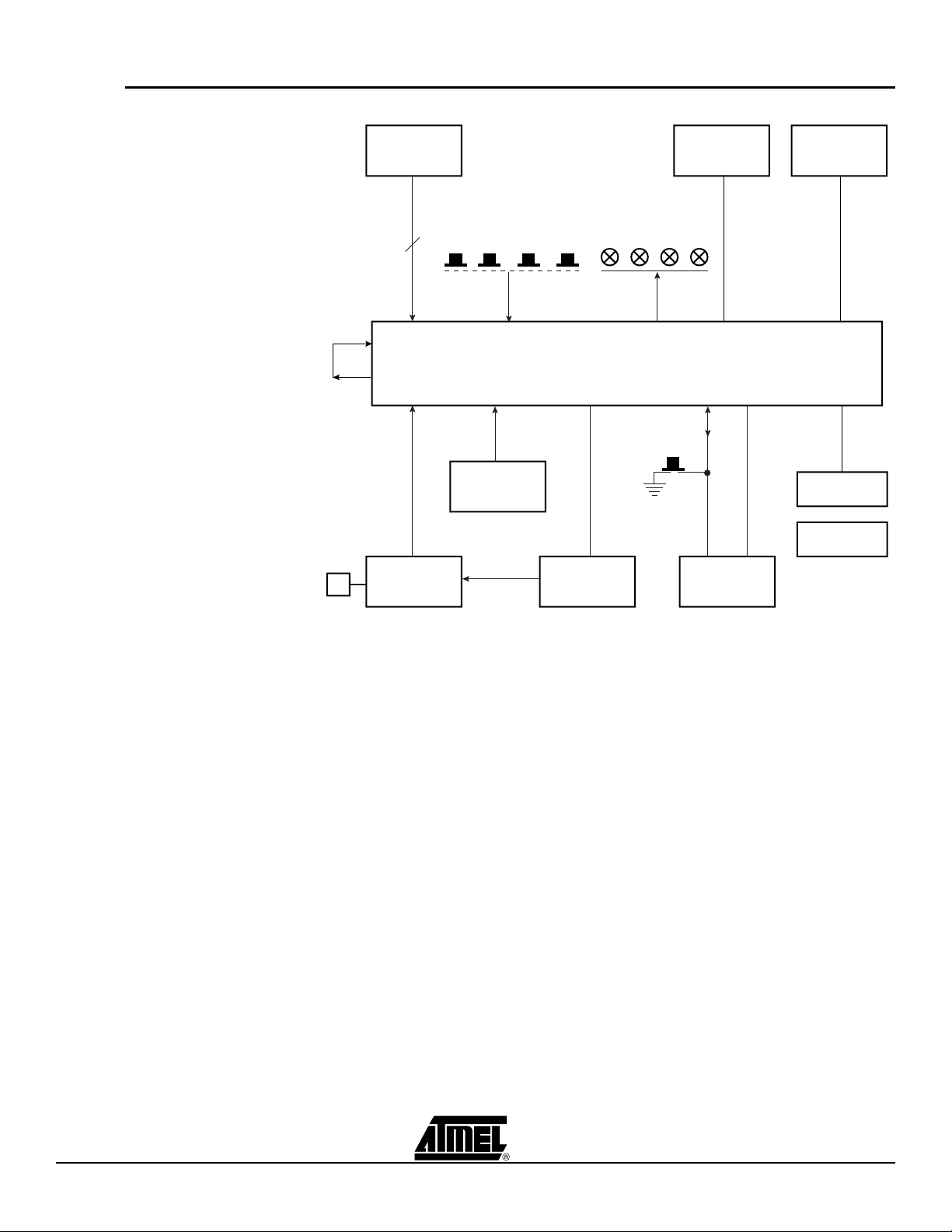
2.5 AT91SAM7S-EK Block Diagram
Figure 2-1. Block Diagram for AT91SAM7S-EK Board
Analog
Inputs
1.8V
7 - 14V DC
Input
4
VDDCORE
VDDOUT
Power
Supply
User Pushbuttons User LEDs
AT91SAM7S256
3.3V
Oscillator,
PLL
5V
USB Device
Pushbutton
NRST
RS232
Driver
UART DBGU
ICE Debug
Port
RS232
Driver
Extension
Connector
User Grid
2-2 AT91SAM7S-EK Evaluation Board User Guide
6112C–ATARM–01-Feb-07

Section 3
Board Description
3.1 AT91SAM7S256 Microcontroller
• Incorporates the ARM7TDMI® ARM® Thumb® Processor
– High-performance 32-bit RISC Architecture
– High-density 16-bit Instruction Set
– Leader in MIPS/Watt
– EmbeddedICE
• 256 Kbytes of Internal High-speed Flash, Organized in 1024 Pages of 256 Bytes
– Single Cycle Access at Up to 30 MHz in Worst Case Conditions,
Prefetch Buffer Optimizing Thumb Instruction Execution at Maximum Speed
– Page Programming Time: 4 ms, Including Page Auto-erase, Full Erase Time: 10
ms
– 10,000 Write Cycles, 10-year Data Retention Capability, Sector Lock Capabilities,
Flash Security Bit
– Fast Flash Programming Interface for High Volume Production
• 64 Kbytes of Internal High-speed SRAM, Single-cycle Access at Maximum Speed
• Memory Controller (MC)
– Embedded Flash Controller, Abort Status and Misalignment Detection
• Reset Controller (RSTC)
– Based on Power-on Reset and Low-power Factory-calibrated Brown-out Detector
– Provides External Reset Signal Shaping and Reset Source Status
• Clock Generator (CKGR)
– Low-power RC Oscillator, 3 to 20 MHz On-chip Oscillator and one PLL
• Power Management Controller (PMC)
– Software Power Optimization Capabilities, Including Slow Clock Mode (Down to
500 Hz) and Idle Mode
– Three Programmable External Clock Signals
• Advanced Interrupt Controller (AIC)
– Individually Maskable, Eight-level Priority, Vectored Interrupt Sources
– Two External Interrupt Sources and One Fast Interrupt Source, Spurious Interrupt
Protected
• Debug Unit (DBGU)
– 2-wire UART and Support for Debug Communication Channel interrupt,
Programmable ICE Access Prevention
• Periodic Interval Timer (PIT)
– 20-bit Programmable Counter plus 12-bit Interval Counter
• Windowed Watchdog (WDT)
™
In-circuit Emulation, Debug Communication Channel Support
AT91SAM7S-EK Evaluation Board User Guide 3-1
6112C–ATARM–01-Feb-07
 Loading...